EP2019482B1 - Système destiné au calcul de l'emplacement et de la vitesse pour un rotor à aimant permanent d'un moteur électrique - Google Patents
Système destiné au calcul de l'emplacement et de la vitesse pour un rotor à aimant permanent d'un moteur électrique Download PDFInfo
- Publication number
- EP2019482B1 EP2019482B1 EP07113231A EP07113231A EP2019482B1 EP 2019482 B1 EP2019482 B1 EP 2019482B1 EP 07113231 A EP07113231 A EP 07113231A EP 07113231 A EP07113231 A EP 07113231A EP 2019482 B1 EP2019482 B1 EP 2019482B1
- Authority
- EP
- European Patent Office
- Prior art keywords
- output
- machine
- speed
- input
- proportional
- Prior art date
- Legal status (The legal status is an assumption and is not a legal conclusion. Google has not performed a legal analysis and makes no representation as to the accuracy of the status listed.)
- Active
Links
- 238000000034 method Methods 0.000 claims abstract description 17
- 230000010354 integration Effects 0.000 claims description 24
- 230000003321 amplification Effects 0.000 claims description 6
- 238000003199 nucleic acid amplification method Methods 0.000 claims description 6
- 238000011144 upstream manufacturing Methods 0.000 claims description 5
- 238000005259 measurement Methods 0.000 claims description 3
- 230000009466 transformation Effects 0.000 description 14
- 238000001514 detection method Methods 0.000 description 8
- 230000008901 benefit Effects 0.000 description 4
- 238000004364 calculation method Methods 0.000 description 3
- 230000004069 differentiation Effects 0.000 description 3
- 230000000694 effects Effects 0.000 description 3
- 238000012986 modification Methods 0.000 description 3
- 230000004048 modification Effects 0.000 description 3
- 230000001360 synchronised effect Effects 0.000 description 3
- 230000015572 biosynthetic process Effects 0.000 description 2
- 230000008859 change Effects 0.000 description 2
- 230000001419 dependent effect Effects 0.000 description 2
- 238000005755 formation reaction Methods 0.000 description 2
- 230000001939 inductive effect Effects 0.000 description 2
- 238000004804 winding Methods 0.000 description 2
- 230000002411 adverse Effects 0.000 description 1
- 238000013459 approach Methods 0.000 description 1
- 230000000295 complement effect Effects 0.000 description 1
- 238000013461 design Methods 0.000 description 1
- 238000011161 development Methods 0.000 description 1
- 230000018109 developmental process Effects 0.000 description 1
- 238000010586 diagram Methods 0.000 description 1
- 238000004870 electrical engineering Methods 0.000 description 1
- 238000005516 engineering process Methods 0.000 description 1
- 230000004907 flux Effects 0.000 description 1
- 230000036039 immunity Effects 0.000 description 1
- 230000001771 impaired effect Effects 0.000 description 1
- 238000013178 mathematical model Methods 0.000 description 1
- 238000010606 normalization Methods 0.000 description 1
- 230000001105 regulatory effect Effects 0.000 description 1
- 230000001953 sensory effect Effects 0.000 description 1
- 230000002123 temporal effect Effects 0.000 description 1
Images
Classifications
-
- H—ELECTRICITY
- H02—GENERATION; CONVERSION OR DISTRIBUTION OF ELECTRIC POWER
- H02P—CONTROL OR REGULATION OF ELECTRIC MOTORS, ELECTRIC GENERATORS OR DYNAMO-ELECTRIC CONVERTERS; CONTROLLING TRANSFORMERS, REACTORS OR CHOKE COILS
- H02P21/00—Arrangements or methods for the control of electric machines by vector control, e.g. by control of field orientation
- H02P21/14—Estimation or adaptation of machine parameters, e.g. flux, current or voltage
- H02P21/141—Flux estimation
-
- H—ELECTRICITY
- H02—GENERATION; CONVERSION OR DISTRIBUTION OF ELECTRIC POWER
- H02P—CONTROL OR REGULATION OF ELECTRIC MOTORS, ELECTRIC GENERATORS OR DYNAMO-ELECTRIC CONVERTERS; CONTROLLING TRANSFORMERS, REACTORS OR CHOKE COILS
- H02P21/00—Arrangements or methods for the control of electric machines by vector control, e.g. by control of field orientation
- H02P21/14—Estimation or adaptation of machine parameters, e.g. flux, current or voltage
- H02P21/18—Estimation of position or speed
Definitions
- the invention relates to a method for determining the drive speed and position of a permanent magnet rotor of an electric brushless machine. This method is particularly suitable for use in a drive control loop.
- the method uses multiphase current measurements on the machine whose measured values are transformed into a longitudinal current vector component and a cross-current vector component as a function of the position determined in a rotor-related d, q coordinate system. Together with the determined (electrical) speed, the longitudinal and transverse vector components of the current and a given voltage as input variables are fed to a mathematical model of the electric machine.
- the machine model generates a first output variable and a second output variable, wherein the first output variable in the d, q coordinate system corresponds to the d or longitudinal vector component and a position detection error, and the second output variable in the d, q coordinate system corresponds to the q or transverse component and a velocity detection error ,
- the two output variables are fed to a tracking controller for determining and outputting the speed, in particular electrical speed, and the position, in particular the electrical angle.
- the invention further relates to the implementation of this method suitable position and / or speed detection device, machine modeling module and speed tracking controller according to the respective first parts / preambles of the independent independent claims 8, 12 and 15.
- US 2005/0 029 972 A1 describes a vectorial, field-oriented drive control for a permanent-magnet-excited, brushless DC motor.
- the drive control comprises: an angle error calculator for calculating a sine and cosine value of an angular difference between an estimated angular position and the actual angular position. This is based on a phase voltage difference of several phases at the input of the stator windings and on the phase currents of a plurality of phases. Further, the drive controller includes an observer for calculating the attitude angle on the basis of the sine and cosine value of the angular difference.
- a system for determining the drive position and / or speed in an electric, brushless machine, in particular a synchronous motor, with a permanent magnet rotor of the type initially mentioned in the first paragraph is known, cf. Article by SM Abu-Sharkh, V. Barinberg "A new approach to rotor position estimation for a PM brushless motor drive", Mediterranean Electrotechnical Conf. 1998, pages 1199-1203 , Thereafter, the rotor position and / or speed estimation also takes place according to the EMF / voltage model of the electric machine.
- the necessary per se, but in practice problematic differentiation / time derivative of current signals is avoided by the use of parameter-dependent low-pass filter whose time-delaying effect is compensated by a downstream proportional and integral tracking controller (PI tracking controller).
- PI tracking controller proportional and integral tracking controller
- the time constant of the low-pass filter corresponds to the stator time constant of the electrical machine.
- the low-pass filters weight the position and velocity detection errors.
- the object of the invention is to simplify the drive position and drive speed determination system in its structural design.
- determination method specified in claim 1 to the determination device specified in claim 8, to the machine modeling module specified in claim 12, and to the tracking controller specified in claim 15.
- machine modeling module specified in claim 12 to the machine modeling module specified in claim 12, and to the tracking controller specified in claim 15.
- the machine model still works with the output of a third deviation variable to the tracking controller; however, the third output variable becomes simply over realizing computational steps generated, which include only weightings by proportional terms with inductance fixed values and summations / difference formations and thus can be implemented with computationally simple and fast-running functional components such as P-members and summation. Consequently, can be achieved with the inventive method, the advantage of an increase in efficiency, especially since neither a temporal differentiation of streams nor additional phase-consuming filter such. For example, the low-pass filters used in the prior art are necessary.
- the two weighting results are suitably modified within the scope of the machine model in accordance with a machine-specific emf constant or a time constant.
- an integration with the specified constants as an integration parameter is then carried out in the tracking controller via a difference formed between the positional and the velocity detection error ("positional deviation” or “speed deviation”) or the corresponding longitudinal and transverse components of the voltage deviation.
- the third output variable fed to the tracking controller is summed with an integration result by means of a difference or otherwise linked, which difference is formed from the difference between the position determination error and the speed determination error. If necessary, the position determination error has previously been amplified proportionally. The result of the combination can then be output from the tracking controller as the determined speed.
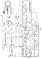
- the stator 1 of a brushless electric machine for example a synchronous motor with permanent magnet rotor, is operated by a converter 2 operating on the basis of pulse width modulation (PWM) with a three-phase three-phase current.
- PWM pulse width modulation
- the two phase currents i 1 , i 2 are tapped or measured by the stator, which are mapped in a 3-to-2 phase transformation unit 3 to a stator-related, orthogonal ⁇ , ⁇ coordinate system.
- two ⁇ , ⁇ vector components i ⁇ , i ⁇ representing the stator current are generated and output to a second, downstream coordinate transformation unit 4.
- This is adapted to a coordinate transformation from the stator-related ⁇ , ⁇ coordinate system to the rotor-related d, q coordinate system with the output of the current longitudinal and Quervektorkomponenten i d , iq make.
- the longitudinal and transverse vector components i d , iq from the stator current are fed as actual values to the series current and cross-current regulators I d , I q for the setpoint / actual value comparison with corresponding longitudinal and cross- current setpoint values i dsoll , i qsoll .
- the longitudinal current setpoint input i dsoll is set to zero, while the cross-flow controller receives the setpoint input I qsoll from an upstream speed controller 5.
- a determined electrical angle ⁇ em is output from the tracking controller 6 and supplied to the second transformation unit 4 and to a third transformation unit 7 complementary thereto.
- the third transformation unit 7 further receives the preset of the current regulators I d, I q longitudinal and transverse voltage vector components u g, u q and forms this u ⁇ , u ⁇ in the stator- ⁇ , ⁇ coordinate system with the specified voltage vector components from.
- the latter voltage vector components are received by a downstream, 2-to-3-phase transformation unit 8, which converts the voltage specification into three phases u 1 , u 2 , u 3 corresponding to the three-phase system for the downstream converter 2.
- FIG. 1 is the tracking controller 6 upstream of a motor modeling module 9.
- This has input interfaces 10 for the determined rotational speed ⁇ em , 11 for the measured longitudinal and transverse currents i d , iq and 12 mapped into the d, q coordinate system for the longitudinal and transverse voltages u d given in the d, q coordinate system , u q up.
- the modeling module 9 has a first output interface 13 for the longitudinal voltage deviation ⁇ u d and a second output interface 14 for the transverse voltage deviation ⁇ u q .
- the determined speed ⁇ em which is supplied via the speed input interfaces 10 to the motor model 9, is weighted with a plurality of separate proportional elements whose gains correspond to the emf constant K E , the motor longitudinal inductance L d and the motor lateral inductance Lq. Furthermore, the input speed ⁇ em is still with a Signum member 15 weighted.
- the outputs of the inductance proportional elements L d , Lq are each connected to a dedicated multiplier M d , Mq.
- the second inputs of the multipliers M d , Mq are each connected to the corresponding one of the two current input interfaces 11 for longitudinal or transverse current i d , iq.
- the respective outputs of the multipliers M d , Mq are supplied to positive and negative voltage summers S d , S q respectively with a positive sign.
- a second input of the longitudinal or transverse voltage summing elements S d , Sq, the longitudinal or transverse voltage specifications u d , u q are also supplied via the voltage input interfaces 12, each with a positive sign.
- the two voltage summators S d , Sq each have an additional negative input (each with a negative sign), which a respective output of two upstream voltage Vorsummierglieder VS d and VSq for the summation of ohmic and inductive longitudinal or transverse voltage intermediate values is assigned, which are generated from the supplied via the current input interfaces 11 longitudinal and transverse currents.
- a proportional element with the amplification r corresponding to the ohmic motor resistance is used for this generation.
- the inductive elements or the longitudinal and transverse inductance L d , Lq, via respective differentiators sL d and sLq are included in the calculation of the intermediate voltage values.
- the inputs of the respective proportional elements r and differentiating elements sL d , sLq are connected to the respective current input interfaces 11.
- the outputs of the respective proportional elements r and of the respective differentiating elements sL d and sLq are then connected to the respective inputs of positive sign of the presumming devices VS d , VSq.
- FIG. 1 is the sign member 15 on the input side connected to the speed input interface 10 and the output side to the first input of a sign multiplier SM d . Its second input communicates with the output of the longitudinal voltage summing S d , and the output of the sign multiplier SM d is connected to the first output interface 13 for the longitudinal vector component ⁇ u d of the voltage deviation in combination. This allows the direction of the Involving the rotor of the electric machine in the calculation of the positional error.
- the EMF motor constant also flows via a proportional element 16 dimensioned with a corresponding gain.
- the EMF proportional element is connected on the input side to the speed input interface 10.
- the EMF proportional element 16 is connected to the negative input of an EMF summing element 17 whose positive input communicates with the output of the transverse voltage summing element Sq.
- the output of the EMF summer 17 goes directly to the second or quadrature deviation output interface 14 of the modeling module for outputting the velocity detection error to the downstream tracking controller 6.
- the tracking controller has two input interfaces 18, 19 for the longitudinal and transverse vector components ⁇ u d , ⁇ u q of the voltage deviation calculated in the modeling module 9.
- the longitudinal vector component corresponds to the attitude detection error, and the transverse vector component to the velocity detection error.
- the input interface 18 for the longitudinal voltage deviation ⁇ u d is fed directly to a proportional element 20 which is dimensioned with the proportional gain kp and is connected on the output side to the minus input of a first tracking summation element 21. Its plus input is connected internally in the tracking controller 6 directly to the input interface for the transverse voltage deviation ⁇ u q .
- the summation result is fed to a first integration element 22, which according to the invention is designed without a proportional component and is dimensioned on the basis of the emf constant K E and a time constant T ⁇ .
- the determined drive angular velocity or rotational speed ⁇ em which via a first tracking controller output interface 23 both to the machine modeling module 9 and to the velocity controller 5 as it were, is produced at its output by integrating the difference between the longitudinal and transverse voltage deviations over time Actual value or for comparison with a speed setpoint ⁇ soll and to calculate a default cross-flow value i qsoll to be performed.
- the determined drive speed ⁇ em is still internally processed in the tracking controller 6 with a second integration element 24, which calculates the electric drive position or angular position therefrom in a manner known per se and outputs it via the second tracking controller output interface 25.
- the electric drive position ⁇ em output via the second tracking controller output interface, is used to control or control the two ⁇ , ⁇ / d, q and d, q / ⁇ , ⁇ transformation units 4, 7, respectively
- the tracking controller according to the invention is already characterized solely by the simplified I-structure with two integrally successive integrators 22, 24.
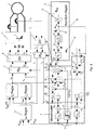
- FIG. 2 is opposite FIG. 1 modified control or drive control system shown.
- the modifications are manifested above all in the blocks labeled by AD of the modeling module 9 and a third input interface 28 of the tracking controller 6.
- FIG. 2 are compared to the modeling arrangement after FIG. 1 the local inductance differentiating elements sL d , sLq replaced by inductance proportional terms A, D with the longitudinal or transverse inductance L d , Lq as the respective gain factor.
- the inductance proportional element A can still be connected in series connection, a further proportional element according to the above-mentioned in connection with the tracking controller 6 proportional element 20 (interpretable as "Lageregul michsglied") upstream or downstream.
- the output of the inductance proportional element A responsible for the longitudinal vector component is followed by a multiplier B, the second input of which is connected to the output of the aforementioned sign element 15, thereby taking into account the direction of rotor rotation or linear motion.
- the output of the multiplier A is passed to the positive input of an inductance summing 26, the second input, linked with a negative sign, to the output of the responsibility for the cross-flow component inductance proportional element D is connected.
- the resulting at the output of the inductance summer 26 differential value is still weighted with an associated proportional element C, the output connected to the third output interface 27 for the Indukt foundedsbondsabweichung ⁇ u L and dimensioned according to the machine-specific emf constant K E and the time constant T ⁇ .
- the value for the inductance voltage deviation ⁇ u L output at the third output interface 27 or at the output of the proportional element C is input to the third input interface 28 of the tracking controller 6.
- the voltage deviation ⁇ u L in the tracking controller is fed to a second tracking summation element 29 with a positive sign.
- the second input of the second tracking summation element 29 is also assigned the output of the first integration element 22 with a positive sign.
- the output of the second tracking summation element 29 is connected directly to the first tracking controller output interface 23 for the feedback of the determined drive speed ⁇ em and to the input of the second integration element 24 for determining and outputting the drive position ⁇ em to the second and third coordinate transformation units 4, 7 in connection.
- FIGS. 1 and 2 is common that the position and speed determination "sensory" alone via measurements of the stator currents I 1 , I 2 takes place.
Landscapes
- Engineering & Computer Science (AREA)
- Power Engineering (AREA)
- Control Of Motors That Do Not Use Commutators (AREA)
- Control Of Ac Motors In General (AREA)
- Control Of Electric Motors In General (AREA)
Claims (18)
- Procédé de détermination de la vitesse (ωem) et de la position (ϕem) d'entraînement électrique d'un rotor à aimant permanent d'une machine électrique linéaire ou rotative sans balais, en particulier pour un circuit de régulation d'entraînement, en utilisant des mesures de courant polyphasées sur la machine, dont les valeurs mesurées (i1, i2) sont transformées, en fonction de la position (ϕem) déterminée, en un système de coordonnées d, q, rapporté au rotor pour générer une composante vectorielle longitudinale de courant (id) et une composante vectorielle transversale de courant (iq), et les composantes vectorielles longitudinale et transversale du courant (id, iq) et d'une tension (Ud, Uq) prédéterminée, conjointement avec la vitesse (ωem) déterminée, sont transmises en tant que variable d'entrée à un modèle mathématique (9) de la machine, et le modèle (9) de la machine génère une première variable de sortie (ΔUd) et une deuxième variable de sortie (ΔUq), la première variable de sortie (ΔUd) correspondant, dans le système de coordonnées d, q, à la composante vectorielle d ou longitudinale ainsi qu'à une erreur de détermination de position et la deuxième variable de sortie (ΔUq) correspondant, dans le système de coordonnées d, q, à la composante vectorielle q ou transversale ainsi qu'à une erreur de détermination de la vitesse, les deux variables de sortie (ΔUd, Δuq) étant transmises à un régulateur de poursuite (6) pour détermination et sortie de la position (ϕem) et/ou de la vitesse (ωem), caractérisé en ce qu'à partir du modèle de la machine est calculée une troisième variable de sortie (ΔUL)a) en pondérant respectivement les composantes vectorielles longitudinale et transversale du courant (id, iq) avec une inductance longitudinale ou transversale (Ld, Lq) de la machine,b) et en formant la troisième variable de sortie (ΔUL) à partir de la différence des deux résultats de pondération,
la troisième variable de sortie (ΔUL) étant transmise au régulateur de poursuite (6) à des fins de traitement pour détermination de la position (ϕem) et de la vitesse (ωem). - Procédé selon la revendication 1, caractérisé en ce que la composante longitudinale de courant (id), pondérée avec l'inductance longitudinale (Ld) est influencée par le signe ou la direction de la vitesse déterminée (ωem).
- Procédé selon la revendication 1 ou 2, caractérisé en ce que, dans le modèle (9) de la machine, la différence formée à partir des deux résultats de pondération est influencée par une constante EMK (KE) spécifique à la machine et/ou par une constante de temps (Tω).
- Procédé selon la revendication 3, caractérisé en ce que, dans le modèle (9) de la machine, la différence est divisée par la constante EMK (KE) et/ou la constante de temps (Tω), et en ce que dans le régulateur de poursuite (6), la même constante EMK (KE) et/ou la même constante de temps (Tω) sont utilisées comme paramètres pour l'intégration d'une différence qui est formée à partir de l'erreur de détermination de position (ΔUd), amplifiée le cas échéant de manière proportionnelle (Kp), et de l'erreur de détermination de vitesse (ΔUq).
- Procédé selon l'une des revendications précédentes, caractérisé en ce que, dans le régulateur de poursuite (6), la troisième variable de sortie (ΔUL) transmise à celui-ci est additionnée ou autrement combinée avec le résultat d'une intégration (22) d'une différence (21) qui est formée à partir de l'erreur de détermination de position (ΔUd), amplifiée le cas échéant de manière proportionnelle (Kp), et de l'erreur de détermination de vitesse (ΔUq), et en ce que le résultat de la combinaison est utilisé et/ou sorti en tant que vitesse déterminée (ωem).
- Procédé selon la revendication 5, caractérisé en ce que la différence (21) est formée dans le régulateur de poursuite (6) et/ou est soumise à une intégration (22) sans composante proportionnelle.
- Procédé selon l'une des revendications précédentes, caractérisé en ce que, dans le modèle (9) de la machine, la composante vectorielle longitudinale (id) du courant est pondérée avec un facteur proportionnel (Kp) qui est utilisé dans le régulateur de poursuite (6) pour régulation de l'erreur de détermination de position (ΔUd).
- Dispositif de détermination de la position (ϕem) et de la vitesse (ωem) d'entraînement électrique d'un rotor à aimant permanent d'une machine électrique linéaire ou rotative sans balais, en particulier pour un circuit de régulation d'entraînement, apte à réaliser le procédé de détermination selon l'une des revendications précédentes, comprenant les composants fonctionnels suivants :a) un module de modélisation (9) de la machine, réalisé selon la technique des circuits et/ou de la programmation, qui présente :aa) des interfaces d'entrée (10, 11, 12) pour des composantes vectorielles machine longitudinale et transversale (id, iq ,Ud, Uq) du courant de stator (i1, i2) et d'une tension prédéterminée, transformées en un système de coordonnées d, q rapporté au rotor, ainsi que pour la vitesse (ωem) déterminée,ab) et au moins deux interfaces de sortie (13, 14) pour des composantes vectorielles (ΔUd, ΔUq), transformées en système de coordonnées d, q, d'un écart de tension calculé de manière interne,b) un régulateur de poursuite (6) réalisé selon la technique des circuits et/ou de programmation pour sortir la position et/ou la vitesse, qui est relié :caractérisé en ce queba) côté entrée aux interfaces de sortie (13, 14), au moins au nombre de deux, du module de modélisation (9),bb) et côté sortie à l'interface d'entrée de vitesse (10) du module de modélisation (9),
le module de modélisation (9) de la machine présente au moins encore une troisième interface de sortie (27) pour un écart de tension d'inductance (ΔUL) et est conçu pour évaluer, au moyen d'éléments à action proportionnelle (A, D), les valeurs d'entrée des composantes vectorielles longitudinale et transversale (id, iq ) du courant avec des valeurs établies d'une inductance longitudinale ou transversale (Ld, Lq) du stator (1) ou de la machine, pour former, au moyen d'un élément sommateur d'inductance (26), la différence à partir des valeurs d'entrée évaluées de manière inductive, et sortir cette différence via la troisième interface de sortie (27), avec laquelle le régulateur de poursuite (6) est relié côté entrée pour recevoir la différence et est conçu pour traiter la différence à des fins de détermination de la vitesse (ωem) et pour sortir cette dernière au niveau de l'interface d'entrée de vitesse (10) du module de modélisation (9). - Dispositif de détermination selon la revendication 8, caractérisé en ce que, dans le modèle (9) de la machine, l'interface d'entrée (11) pour la composante vectorielle longitudinale (id) du courant est transmise à un élément à action proportionnelle (A) avec une amplification proportionnelle (kp), et en ce qu'est disposé dans le régulateur de poursuite (6) un élément à action proportionnelle (20) ayant la même amplification proportionnelle (kp) ou une amplification similaire pour pondération de l'erreur de détermination de position (ΔUd).
- Dispositif de détermination selon la revendication 9, caractérisé en ce que, dans le modèle de la machine, l'élément à action proportionnelle ayant l'amplification proportionnelle (kp) est monté en série avec un élément à action proportionnelle d'inductance (A) dimensionné conformément à la valeur établie d'inductance longitudinale (Ld).
- Dispositif de détermination selon la revendication 8, 9 ou 10, caractérisé en ce que la sortie de l'élément sommateur d'inductance (26) est reliée à la troisième interface de sortie (27) via un élément à action proportionnelle (C) dimensionné conformément à une constante EMK (KE) et/ou à une constante de temps (Tω), et en ce que, dans le régulateur de poursuite (6), en vue du traitement dans celui-ci d'une combinaison, éventuellement pondérée ou autrement traitée, des composantes vectorielles d, q (ΔUd, ΔUq) de l'écart de tension transmis au module de modélisation (9) placé en amont, est disposé un premier circuit d'intégration (22) qui est réglé conformément à la même constante EMK (KE) et/ou constante de temps (Tω) ou à une constante EMK et/ou de temps similaire(s).
- Module de modélisation de machine pour une machine électrique linéaire ou rotative sans balais équipée d'un rotor à aimant permanent, apte à être utilisé dans le dispositif de détermination selon la revendication 8 ou 9, comprenanta) des interfaces d'entrée (11) pour des composantes vectorielles machine longitudinale et transversale (id, iq ,Ud, Uq) du courant et d'une tension prédéterminée, transformées en un système de coordonnées d, q rapporté au rotor, ainsi que pour une vitesse (ωem) de la machine, déterminée de manière externe,b) et au moins deux interfaces de sortie (13, 14) pour des composantes vectorielles (ΔUd, ΔUq) longitudinale et transversale, transformées en système de coordonnées d, q, d'un écart de tension calculé de manière interne,c) et plusieurs éléments à action proportionnelle (r, A, D) pour pondération des composantes vectorielles de courant (id, iq) avec une résistance ohmique de stator ou de machine (r) et une ou plusieurs inductances de stator ou de machine (Ld, Lq),caractérisé par
au moins encore une troisième interface de sortie (27) pour un écart de tension d'inductance (ΔUL), pour la génération duquel un élément à action proportionnelle d'inductance longitudinale et un élément à action proportionnelle d'inductance transversale (A, D) avec des amplifications conformément à une inductance longitudinale ou transversale (Ld, Lq) sont disposés et reliés, côté entrée, aux interfaces d'entrée (11) des composantes vectorielles longitudinale et transversale de courant (id, iq), les deux sorties des éléments à action proportionnelle étant couplées directement ou indirectement aux entrées d'un élément sommateur d'inductance (26), et la sortie de l'élément sommateur d'inductance (26) étant couplée directement ou indirectement à la troisième interface de sortie (27). - Module de modélisation de machine selon la revendication 12, caractérisé par un élément de signe (15) qui, à son entrée, est relié à l'interface d'entrée (10) de la vitesse machine (ωem) déterminée de manière externe et, côté sortie, est combiné, via un élément multiplicateur (B), avec la sortie d'un élément à action proportionnelle (A, D) qui pondère les composantes vectorielles longitudinale ou transversale de courant (id, iq) avec l'inductance longitudinale ou transversale (Ld, Lq).
- Module de modélisation de machine selon la revendication 12 ou 13, caractérisé en ce que la sortie de l'élément sommateur d'inductance (26) est transmis à la troisième interface de sortie (27) par l'intermédiaire d'un élément à action proportionnelle (C) dont l'amplification proportionnelle est définie via des valeurs établies d'une constante EMK (KE) et/ou d'une constante de temps (Tω) spécifiques à la machine.
- Régulateur de poursuite (6) pour réalisation du procédé ou pour utilisation dans le dispositif de détermination selon l'une des revendications précédentes, comportant les caractéristiques suivantes :a) au moins deux interfaces d'entrée (18, 19) pour des composantes vectorielles longitudinale et transversale (ΔUd, ΔUq), transformées en système de coordonnées d, q, d'un écart de tension calculé de manière externe et transmis,b) au moins une interface de sortie (23) pour une vitesse d'entraînement (ωem) déterminée de manière interne,c) un élément à action proportionnelle (20, kp) dont l'entrée est reliée à l'interface d'entrée (18) de la composante vectorielle longitudinale (ΔUd) de l'écart de tension ou de l'erreur de détermination de position (ΔU) calculé(e) de manière externe,d) un premier élément sommateur de poursuite (21) dont la première entrée est reliée à la sortie de l'élément à action proportionnelle (20, kp) et dont la deuxième entrée est reliée, via la deuxième interface d'entrée (19), à la composante vectorielle transversale (ΔUq) de l'écart de tension ou de l'erreur de détermination de vitesse,caractérisé par
au moins encore une troisième interface d'entrée (28) pour un écart de tension d'inductance (ΔUL) transmis de manière externe, la troisième interface d'entrée (28) étant reliée à la première entrée d'un élément de combinaison dont la seconde entrée détecte indirectement ou directement la sortie du premier élément sommateur de poursuite (21) et dont la sortie peut être prélevée par l'intermédiaire de l'interface de sortie (23), au moins au nombre de une, pour la vitesse d'entraînement (Δem). - Régulateur de poursuite selon la revendication 15, caractérisé en ce que l'élément de combinaison est conçu en tant que deuxième élément sommateur de poursuite (29) placé indirectement ou directement en aval du premier élément sommateur de poursuite (21).
- Régulateur de poursuite selon la revendication 15 ou 16, caractérisé en ce qu'un seul élément d'intégration (22) est interposé entre le premier élément sommateur de poursuite (21) et l'élément de combinaison ou deuxième élément sommateur de poursuite (29).
- Régulateur de poursuite selon la revendication 17, caractérisé en ce que l'élément d'intégration (22) est dimensionné sans composante proportionnelle et/ou sur la base de la constante EMK (KE) et/ou de la constante de temps (Tω).
Priority Applications (7)
| Application Number | Priority Date | Filing Date | Title |
|---|---|---|---|
| EP07113231A EP2019482B1 (fr) | 2007-07-26 | 2007-07-26 | Système destiné au calcul de l'emplacement et de la vitesse pour un rotor à aimant permanent d'un moteur électrique |
| DE502007003311T DE502007003311D1 (de) | 2007-07-26 | 2007-07-26 | System zur Lage- und Geschwindigkeitsermittlung bei einem Permanentmagnet-Läufer einer elektrischen Maschine |
| AT07113231T ATE463073T1 (de) | 2007-07-26 | 2007-07-26 | System zur lage- und geschwindigkeitsermittlung bei einem permanentmagnet-läufer einer elektrischen maschine |
| DE202008009574U DE202008009574U1 (de) | 2007-07-26 | 2008-07-16 | System zur Lage- und Geschwindigkeitsermittlung bei einem Permanentmagnet-Läufer einer elektrischen Maschine |
| US12/177,182 US7999498B2 (en) | 2007-07-26 | 2008-07-22 | System for estimation of position and speed in a permanent magnet rotor of an electrical motor |
| JP2008191634A JP5501580B2 (ja) | 2007-07-26 | 2008-07-25 | 電気モータの永久磁石ロータにおける位置および速度の推定システム |
| CN2008101443425A CN101399514B (zh) | 2007-07-26 | 2008-07-25 | 用于检测电机永磁转子的位置和速度的系统 |
Applications Claiming Priority (1)
| Application Number | Priority Date | Filing Date | Title |
|---|---|---|---|
| EP07113231A EP2019482B1 (fr) | 2007-07-26 | 2007-07-26 | Système destiné au calcul de l'emplacement et de la vitesse pour un rotor à aimant permanent d'un moteur électrique |
Publications (2)
| Publication Number | Publication Date |
|---|---|
| EP2019482A1 EP2019482A1 (fr) | 2009-01-28 |
| EP2019482B1 true EP2019482B1 (fr) | 2010-03-31 |
Family
ID=38562827
Family Applications (1)
| Application Number | Title | Priority Date | Filing Date |
|---|---|---|---|
| EP07113231A Active EP2019482B1 (fr) | 2007-07-26 | 2007-07-26 | Système destiné au calcul de l'emplacement et de la vitesse pour un rotor à aimant permanent d'un moteur électrique |
Country Status (6)
| Country | Link |
|---|---|
| US (1) | US7999498B2 (fr) |
| EP (1) | EP2019482B1 (fr) |
| JP (1) | JP5501580B2 (fr) |
| CN (1) | CN101399514B (fr) |
| AT (1) | ATE463073T1 (fr) |
| DE (2) | DE502007003311D1 (fr) |
Families Citing this family (18)
| Publication number | Priority date | Publication date | Assignee | Title |
|---|---|---|---|---|
| US8248009B2 (en) | 2008-11-17 | 2012-08-21 | Rockwell Automation Technologies, Inc. | Motor controller having integrated communications configurations |
| US8375809B2 (en) * | 2010-03-02 | 2013-02-19 | Hamilton Sundstrand Corporation | Load monitoring for electromechanical systems |
| EP2421146B1 (fr) * | 2010-08-16 | 2015-02-11 | Baumüller Nürnberg GmbH | Dispositif et procédé d'identification des paramètres de référence magnéto-mécaniques d'un moteur synchrone triphasé sans utilisation d'encodeur de vitesse |
| GB2489434A (en) * | 2011-03-25 | 2012-10-03 | Technelec Ltd | Controlling an electrical machine with an observer |
| ES2673694T3 (es) | 2011-07-28 | 2018-06-25 | Vestas Wind Systems A/S | Método de control de posición sin sensor de una máquina eléctrica |
| EP2552014A3 (fr) | 2011-07-28 | 2016-08-17 | Vestas Wind Systems A/S | Procédé de contrôle de position d'une machine électrique sans capteur |
| CN102507189B (zh) * | 2011-09-23 | 2014-04-02 | 奇瑞汽车股份有限公司 | 混合动力电机转子位置的测试方法和测试系统 |
| DE202012000091U1 (de) | 2012-01-05 | 2012-03-16 | Frank Mayer | Einrichtung zur Regelung einer Drehfeldmaschine an einem Direktumrichter bis Drehzahl Null |
| US8823301B2 (en) | 2012-11-05 | 2014-09-02 | Whirlpool Corporation | Method and device for detecting rotor position in a permanent magnet synchronous motor-driven washing machine |
| CN103346727B (zh) * | 2013-07-27 | 2016-01-20 | 湖北立锐机电有限公司 | 应用于pmsm无位置控制的角度跟踪观测器及其实现方法 |
| CA2942148C (fr) * | 2014-04-02 | 2018-03-27 | Canrig Drilling Technology Ltd. | Procede de regulation de couple dans des moteurs d'entrainement a aimants permanents |
| US10655377B2 (en) | 2016-04-21 | 2020-05-19 | Westinghouse Air Brake Technologies Corporation | Method and system for detecting an obstruction of a passenger door |
| JP6661509B2 (ja) * | 2016-10-04 | 2020-03-11 | 日立オートモティブシステムズ株式会社 | ブラシレスモータの制御装置及び制御方法 |
| JP6757226B2 (ja) * | 2016-10-07 | 2020-09-16 | 株式会社マキタ | 電動工具 |
| GB2579633B (en) | 2018-12-07 | 2023-02-01 | Zf Automotive Uk Ltd | A method of characterising a permanent magnet synchronous motor |
| CN112968643B (zh) * | 2021-02-01 | 2022-08-26 | 南京邮电大学 | 一种基于自适应扩展h∞滤波的无刷直流电机参数辨识方法 |
| CN115459663A (zh) | 2021-05-20 | 2022-12-09 | 台达电子工业股份有限公司 | 马达控制方法 |
| JP7362003B2 (ja) * | 2021-08-24 | 2023-10-16 | 三菱電機株式会社 | 回転機の制御装置 |
Family Cites Families (8)
| Publication number | Priority date | Publication date | Assignee | Title |
|---|---|---|---|---|
| JP3411878B2 (ja) * | 2000-03-06 | 2003-06-03 | 株式会社日立製作所 | 同期モータの回転子位置推定方法、位置センサレス制御方法及び制御装置 |
| JP3719910B2 (ja) * | 2000-05-30 | 2005-11-24 | 株式会社東芝 | モータ制御装置 |
| JP3651595B2 (ja) * | 2001-12-13 | 2005-05-25 | 株式会社東芝 | 洗濯機のインバータ装置及び洗濯乾燥機のインバータ装置 |
| JP2004015858A (ja) * | 2002-06-04 | 2004-01-15 | Meidensha Corp | Pmモータの位置センサレス制御方式 |
| JP3972124B2 (ja) * | 2002-07-10 | 2007-09-05 | 株式会社日立製作所 | 同期電動機の速度制御装置 |
| JP4230276B2 (ja) | 2003-05-19 | 2009-02-25 | 本田技研工業株式会社 | ブラシレスdcモータの制御装置 |
| CN1767356A (zh) * | 2004-10-27 | 2006-05-03 | 乐金电子(天津)电器有限公司 | 直流无刷电机的速度控制装置及其方法 |
| CN100413207C (zh) * | 2006-11-17 | 2008-08-20 | 清华大学 | 一种异频供电永磁同步电动机矢量控制系统 |
-
2007
- 2007-07-26 DE DE502007003311T patent/DE502007003311D1/de active Active
- 2007-07-26 AT AT07113231T patent/ATE463073T1/de active
- 2007-07-26 EP EP07113231A patent/EP2019482B1/fr active Active
-
2008
- 2008-07-16 DE DE202008009574U patent/DE202008009574U1/de not_active Expired - Lifetime
- 2008-07-22 US US12/177,182 patent/US7999498B2/en active Active
- 2008-07-25 CN CN2008101443425A patent/CN101399514B/zh active Active
- 2008-07-25 JP JP2008191634A patent/JP5501580B2/ja not_active Expired - Fee Related
Also Published As
| Publication number | Publication date |
|---|---|
| CN101399514A (zh) | 2009-04-01 |
| US7999498B2 (en) | 2011-08-16 |
| DE202008009574U1 (de) | 2009-03-12 |
| ATE463073T1 (de) | 2010-04-15 |
| CN101399514B (zh) | 2012-09-05 |
| JP2009033963A (ja) | 2009-02-12 |
| EP2019482A1 (fr) | 2009-01-28 |
| US20090030645A1 (en) | 2009-01-29 |
| JP5501580B2 (ja) | 2014-05-21 |
| DE502007003311D1 (de) | 2010-05-12 |
Similar Documents
| Publication | Publication Date | Title |
|---|---|---|
| EP2019482B1 (fr) | Système destiné au calcul de l'emplacement et de la vitesse pour un rotor à aimant permanent d'un moteur électrique | |
| EP2023479B1 (fr) | Dispositif destiné au calcul de la vitesse et/ou de l'emplacement sans fil incluant un arrêt pour un rotor magnétique permanent de machine électrique | |
| DE60024222T2 (de) | Verfahren zur Schätzung der Rotorlage eines Synchronmotors, Verfahren zur Steuerung eines sensorlosen Synchronmotors und eine Steuerung für einen Synchronmotor | |
| DE102007061905B4 (de) | Hochansprechende Permanentmagnetmotorsteuerung | |
| DE60224021T2 (de) | Steuergerät für einen Elektromotor | |
| DE10206410A1 (de) | Rotorwinkel-Erfassungsvorrichtung für bürstenlose Gleichstrommotoren | |
| EP0127158B1 (fr) | Procédé et appareillage pour la détermination du vecteur de flux d'une machine à champ tournant d'après le courant stator et la tension stator et utilisation de ceux-ci | |
| EP2226929B1 (fr) | Système de surveillance de la plausibilité pour des mesures de mouvements sur un dispositif d'entraînement électrique | |
| DE112010001465T5 (de) | Wechselstrommotor-Steuervorrichtung und Wechselstrommotor-Treibersystem | |
| DE10206191B4 (de) | Verfahren zur feldorientierten Regelung einer permanenterregten Synchronmaschine mit Reluktanzmoment | |
| DE112008003590B4 (de) | Magnetpolpositions-Schätzverfahren für einen AC-Synchronmotor | |
| DE102008058872A1 (de) | Verfahren und System zur sensorlosen Steuerung eines Elektromotors | |
| DE10330791A1 (de) | Vektor-orientiertes Steuerungssystem für synchrone Maschinen mit Permanent-Magneten unter Verwendung eines Beobachters für die Parameter eines offenen Regelkreises | |
| DE112004002619T5 (de) | Motorregelanordnung | |
| DE102013207121A1 (de) | System zur Steuerung einer Regelgrösse einer rotierenden Maschine | |
| WO2016207383A1 (fr) | Procédé permettant de déterminer des caractéristiques dépendantes du courant ou dépendantes de la position angulaire de rotation d'une machine électrique et convertisseur de fréquence | |
| DE112020005654T5 (de) | Motorantriebseinrichtung, ausseneinheit einer klimaanlage, die diese enthält, undmotorantriebssteuerverfahren | |
| EP2144362B1 (fr) | Procédé et agencement pour l'observation de la vitesse d'entraînement d'un rotor à aimant permanent dans un circuit d'entraînement | |
| DE102008058739B4 (de) | Verfahren zum feldorientierten Betrieb einer geberlosen Asynchronmaschine bis zum Stillstand | |
| DE102010021488A1 (de) | Verfahren zur (kupfer-)verlustoptimalen Regelung einer Asynchronmaschine mit einem Frequenzumrichter | |
| DE102019116339B4 (de) | Motoransteuervorrichtung | |
| WO2012037983A1 (fr) | Procédé de régulation optimisée en termes de pertes (dans le cuivre) pour un moteur asynchrone au moyen d'un convertisseur | |
| DE102008045622B4 (de) | Verfahren zur Adaption einer Polradorientierung einer nicht linearen, geberlosen, permanenterregten Synchromaschine | |
| DE102008007100A1 (de) | Verfahren und Vorrichtung zur Stromregelung oder Momentenregelung | |
| DE102019130638A1 (de) | Vorrichtung und Verfahren zur Steuerung eines Motors |
Legal Events
| Date | Code | Title | Description |
|---|---|---|---|
| PUAI | Public reference made under article 153(3) epc to a published international application that has entered the european phase |
Free format text: ORIGINAL CODE: 0009012 |
|
| AK | Designated contracting states |
Kind code of ref document: A1 Designated state(s): AT BE BG CH CY CZ DE DK EE ES FI FR GB GR HU IE IS IT LI LT LU LV MC MT NL PL PT RO SE SI SK TR |
|
| AX | Request for extension of the european patent |
Extension state: AL BA HR MK RS |
|
| 17P | Request for examination filed |
Effective date: 20090605 |
|
| GRAP | Despatch of communication of intention to grant a patent |
Free format text: ORIGINAL CODE: EPIDOSNIGR1 |
|
| AKX | Designation fees paid |
Designated state(s): AT BE BG CH CY CZ DE DK EE ES FI FR GB GR HU IE IS IT LI LT LU LV MC MT NL PL PT RO SE SI SK TR |
|
| GRAS | Grant fee paid |
Free format text: ORIGINAL CODE: EPIDOSNIGR3 |
|
| GRAA | (expected) grant |
Free format text: ORIGINAL CODE: 0009210 |
|
| AK | Designated contracting states |
Kind code of ref document: B1 Designated state(s): AT BE BG CH CY CZ DE DK EE ES FI FR GB GR HU IE IS IT LI LT LU LV MC MT NL PL PT RO SE SI SK TR |
|
| REG | Reference to a national code |
Ref country code: CH Ref legal event code: EP Ref country code: GB Ref legal event code: FG4D Free format text: NOT ENGLISH |
|
| REG | Reference to a national code |
Ref country code: IE Ref legal event code: FG4D |
|
| REF | Corresponds to: |
Ref document number: 502007003311 Country of ref document: DE Date of ref document: 20100512 Kind code of ref document: P |
|
| REG | Reference to a national code |
Ref country code: NL Ref legal event code: T3 |
|
| PG25 | Lapsed in a contracting state [announced via postgrant information from national office to epo] |
Ref country code: LT Free format text: LAPSE BECAUSE OF FAILURE TO SUBMIT A TRANSLATION OF THE DESCRIPTION OR TO PAY THE FEE WITHIN THE PRESCRIBED TIME-LIMIT Effective date: 20100331 |
|
| REG | Reference to a national code |
Ref country code: CH Ref legal event code: NV Representative=s name: SCHNEIDER FELDMANN AG PATENT- UND MARKENANWAELTE |
|
| LTIE | Lt: invalidation of european patent or patent extension |
Effective date: 20100331 |
|
| PG25 | Lapsed in a contracting state [announced via postgrant information from national office to epo] |
Ref country code: FI Free format text: LAPSE BECAUSE OF FAILURE TO SUBMIT A TRANSLATION OF THE DESCRIPTION OR TO PAY THE FEE WITHIN THE PRESCRIBED TIME-LIMIT Effective date: 20100331 Ref country code: LV Free format text: LAPSE BECAUSE OF FAILURE TO SUBMIT A TRANSLATION OF THE DESCRIPTION OR TO PAY THE FEE WITHIN THE PRESCRIBED TIME-LIMIT Effective date: 20100331 Ref country code: SI Free format text: LAPSE BECAUSE OF FAILURE TO SUBMIT A TRANSLATION OF THE DESCRIPTION OR TO PAY THE FEE WITHIN THE PRESCRIBED TIME-LIMIT Effective date: 20100331 Ref country code: PL Free format text: LAPSE BECAUSE OF FAILURE TO SUBMIT A TRANSLATION OF THE DESCRIPTION OR TO PAY THE FEE WITHIN THE PRESCRIBED TIME-LIMIT Effective date: 20100331 |
|
| REG | Reference to a national code |
Ref country code: IE Ref legal event code: FD4D |
|
| PG25 | Lapsed in a contracting state [announced via postgrant information from national office to epo] |
Ref country code: SE Free format text: LAPSE BECAUSE OF FAILURE TO SUBMIT A TRANSLATION OF THE DESCRIPTION OR TO PAY THE FEE WITHIN THE PRESCRIBED TIME-LIMIT Effective date: 20100331 Ref country code: CY Free format text: LAPSE BECAUSE OF FAILURE TO SUBMIT A TRANSLATION OF THE DESCRIPTION OR TO PAY THE FEE WITHIN THE PRESCRIBED TIME-LIMIT Effective date: 20100331 Ref country code: EE Free format text: LAPSE BECAUSE OF FAILURE TO SUBMIT A TRANSLATION OF THE DESCRIPTION OR TO PAY THE FEE WITHIN THE PRESCRIBED TIME-LIMIT Effective date: 20100331 Ref country code: ES Free format text: LAPSE BECAUSE OF FAILURE TO SUBMIT A TRANSLATION OF THE DESCRIPTION OR TO PAY THE FEE WITHIN THE PRESCRIBED TIME-LIMIT Effective date: 20100712 Ref country code: RO Free format text: LAPSE BECAUSE OF FAILURE TO SUBMIT A TRANSLATION OF THE DESCRIPTION OR TO PAY THE FEE WITHIN THE PRESCRIBED TIME-LIMIT Effective date: 20100331 |
|
| PG25 | Lapsed in a contracting state [announced via postgrant information from national office to epo] |
Ref country code: IS Free format text: LAPSE BECAUSE OF FAILURE TO SUBMIT A TRANSLATION OF THE DESCRIPTION OR TO PAY THE FEE WITHIN THE PRESCRIBED TIME-LIMIT Effective date: 20100731 Ref country code: CZ Free format text: LAPSE BECAUSE OF FAILURE TO SUBMIT A TRANSLATION OF THE DESCRIPTION OR TO PAY THE FEE WITHIN THE PRESCRIBED TIME-LIMIT Effective date: 20100331 Ref country code: SK Free format text: LAPSE BECAUSE OF FAILURE TO SUBMIT A TRANSLATION OF THE DESCRIPTION OR TO PAY THE FEE WITHIN THE PRESCRIBED TIME-LIMIT Effective date: 20100331 |
|
| BERE | Be: lapsed |
Owner name: BAUMULLER NURNBERG G.M.B.H. Effective date: 20100731 |
|
| PG25 | Lapsed in a contracting state [announced via postgrant information from national office to epo] |
Ref country code: DK Free format text: LAPSE BECAUSE OF FAILURE TO SUBMIT A TRANSLATION OF THE DESCRIPTION OR TO PAY THE FEE WITHIN THE PRESCRIBED TIME-LIMIT Effective date: 20100331 Ref country code: IE Free format text: LAPSE BECAUSE OF FAILURE TO SUBMIT A TRANSLATION OF THE DESCRIPTION OR TO PAY THE FEE WITHIN THE PRESCRIBED TIME-LIMIT Effective date: 20100331 Ref country code: PT Free format text: LAPSE BECAUSE OF FAILURE TO SUBMIT A TRANSLATION OF THE DESCRIPTION OR TO PAY THE FEE WITHIN THE PRESCRIBED TIME-LIMIT Effective date: 20100802 |
|
| PLBE | No opposition filed within time limit |
Free format text: ORIGINAL CODE: 0009261 |
|
| STAA | Information on the status of an ep patent application or granted ep patent |
Free format text: STATUS: NO OPPOSITION FILED WITHIN TIME LIMIT |
|
| PG25 | Lapsed in a contracting state [announced via postgrant information from national office to epo] |
Ref country code: MC Free format text: LAPSE BECAUSE OF NON-PAYMENT OF DUE FEES Effective date: 20100731 |
|
| 26N | No opposition filed |
Effective date: 20110104 |
|
| PG25 | Lapsed in a contracting state [announced via postgrant information from national office to epo] |
Ref country code: BE Free format text: LAPSE BECAUSE OF NON-PAYMENT OF DUE FEES Effective date: 20100731 |
|
| PG25 | Lapsed in a contracting state [announced via postgrant information from national office to epo] |
Ref country code: MT Free format text: LAPSE BECAUSE OF FAILURE TO SUBMIT A TRANSLATION OF THE DESCRIPTION OR TO PAY THE FEE WITHIN THE PRESCRIBED TIME-LIMIT Effective date: 20100331 |
|
| PG25 | Lapsed in a contracting state [announced via postgrant information from national office to epo] |
Ref country code: LU Free format text: LAPSE BECAUSE OF NON-PAYMENT OF DUE FEES Effective date: 20100726 Ref country code: BG Free format text: LAPSE BECAUSE OF FAILURE TO SUBMIT A TRANSLATION OF THE DESCRIPTION OR TO PAY THE FEE WITHIN THE PRESCRIBED TIME-LIMIT Effective date: 20100331 Ref country code: HU Free format text: LAPSE BECAUSE OF FAILURE TO SUBMIT A TRANSLATION OF THE DESCRIPTION OR TO PAY THE FEE WITHIN THE PRESCRIBED TIME-LIMIT Effective date: 20101001 |
|
| PG25 | Lapsed in a contracting state [announced via postgrant information from national office to epo] |
Ref country code: TR Free format text: LAPSE BECAUSE OF FAILURE TO SUBMIT A TRANSLATION OF THE DESCRIPTION OR TO PAY THE FEE WITHIN THE PRESCRIBED TIME-LIMIT Effective date: 20100331 |
|
| PG25 | Lapsed in a contracting state [announced via postgrant information from national office to epo] |
Ref country code: BG Free format text: LAPSE BECAUSE OF FAILURE TO SUBMIT A TRANSLATION OF THE DESCRIPTION OR TO PAY THE FEE WITHIN THE PRESCRIBED TIME-LIMIT Effective date: 20100630 |
|
| PGFP | Annual fee paid to national office [announced via postgrant information from national office to epo] |
Ref country code: NL Payment date: 20130722 Year of fee payment: 7 |
|
| PG25 | Lapsed in a contracting state [announced via postgrant information from national office to epo] |
Ref country code: GR Free format text: LAPSE BECAUSE OF FAILURE TO SUBMIT A TRANSLATION OF THE DESCRIPTION OR TO PAY THE FEE WITHIN THE PRESCRIBED TIME-LIMIT Effective date: 20100331 |
|
| REG | Reference to a national code |
Ref country code: NL Ref legal event code: V1 Effective date: 20150201 |
|
| PG25 | Lapsed in a contracting state [announced via postgrant information from national office to epo] |
Ref country code: NL Free format text: LAPSE BECAUSE OF NON-PAYMENT OF DUE FEES Effective date: 20150201 |
|
| REG | Reference to a national code |
Ref country code: FR Ref legal event code: PLFP Year of fee payment: 10 |
|
| REG | Reference to a national code |
Ref country code: FR Ref legal event code: PLFP Year of fee payment: 11 |
|
| REG | Reference to a national code |
Ref country code: FR Ref legal event code: PLFP Year of fee payment: 12 |
|
| REG | Reference to a national code |
Ref country code: CH Ref legal event code: PFA Owner name: BAUMUELLER NUERNBERG GMBH, DE Free format text: FORMER OWNER: BAUMUELLER NUERNBERG GMBH, DE |
|
| PGFP | Annual fee paid to national office [announced via postgrant information from national office to epo] |
Ref country code: IT Payment date: 20230731 Year of fee payment: 17 Ref country code: GB Payment date: 20230724 Year of fee payment: 17 Ref country code: CH Payment date: 20230802 Year of fee payment: 17 Ref country code: AT Payment date: 20230718 Year of fee payment: 17 |
|
| PGFP | Annual fee paid to national office [announced via postgrant information from national office to epo] |
Ref country code: FR Payment date: 20230724 Year of fee payment: 17 Ref country code: DE Payment date: 20230720 Year of fee payment: 17 |