EP2019482A1 - Système destiné au calcul de l'emplacement et de la vitesse pour un rotor à aimant permanent d'un moteur électrique - Google Patents
Système destiné au calcul de l'emplacement et de la vitesse pour un rotor à aimant permanent d'un moteur électrique Download PDFInfo
- Publication number
- EP2019482A1 EP2019482A1 EP07113231A EP07113231A EP2019482A1 EP 2019482 A1 EP2019482 A1 EP 2019482A1 EP 07113231 A EP07113231 A EP 07113231A EP 07113231 A EP07113231 A EP 07113231A EP 2019482 A1 EP2019482 A1 EP 2019482A1
- Authority
- EP
- European Patent Office
- Prior art keywords
- output
- longitudinal
- proportional
- machine
- input
- Prior art date
- Legal status (The legal status is an assumption and is not a legal conclusion. Google has not performed a legal analysis and makes no representation as to the accuracy of the status listed.)
- Granted
Links
- 238000000034 method Methods 0.000 claims abstract description 18
- 238000001514 detection method Methods 0.000 claims description 19
- 230000010354 integration Effects 0.000 claims description 13
- 238000011144 upstream manufacturing Methods 0.000 claims description 5
- 238000005259 measurement Methods 0.000 claims description 3
- 230000002787 reinforcement Effects 0.000 claims 1
- 230000009466 transformation Effects 0.000 description 14
- 230000008901 benefit Effects 0.000 description 4
- 238000004364 calculation method Methods 0.000 description 3
- 230000000694 effects Effects 0.000 description 3
- 230000001360 synchronised effect Effects 0.000 description 3
- 230000015572 biosynthetic process Effects 0.000 description 2
- 230000008859 change Effects 0.000 description 2
- 230000001419 dependent effect Effects 0.000 description 2
- 230000004069 differentiation Effects 0.000 description 2
- 238000005755 formation reaction Methods 0.000 description 2
- 230000001939 inductive effect Effects 0.000 description 2
- 230000002411 adverse Effects 0.000 description 1
- 230000003321 amplification Effects 0.000 description 1
- 238000013459 approach Methods 0.000 description 1
- 230000000295 complement effect Effects 0.000 description 1
- 238000013461 design Methods 0.000 description 1
- 238000011161 development Methods 0.000 description 1
- 230000018109 developmental process Effects 0.000 description 1
- 238000010586 diagram Methods 0.000 description 1
- 238000005516 engineering process Methods 0.000 description 1
- 230000004907 flux Effects 0.000 description 1
- 238000013178 mathematical model Methods 0.000 description 1
- 238000012986 modification Methods 0.000 description 1
- 230000004048 modification Effects 0.000 description 1
- 238000003199 nucleic acid amplification method Methods 0.000 description 1
- 230000001105 regulatory effect Effects 0.000 description 1
- 230000001953 sensory effect Effects 0.000 description 1
- 230000002123 temporal effect Effects 0.000 description 1
- 238000004804 winding Methods 0.000 description 1
Images

Classifications
-
- H—ELECTRICITY
- H02—GENERATION; CONVERSION OR DISTRIBUTION OF ELECTRIC POWER
- H02P—CONTROL OR REGULATION OF ELECTRIC MOTORS, ELECTRIC GENERATORS OR DYNAMO-ELECTRIC CONVERTERS; CONTROLLING TRANSFORMERS, REACTORS OR CHOKE COILS
- H02P21/00—Arrangements or methods for the control of electric machines by vector control, e.g. by control of field orientation
- H02P21/14—Estimation or adaptation of machine parameters, e.g. flux, current or voltage
- H02P21/141—Flux estimation
-
- H—ELECTRICITY
- H02—GENERATION; CONVERSION OR DISTRIBUTION OF ELECTRIC POWER
- H02P—CONTROL OR REGULATION OF ELECTRIC MOTORS, ELECTRIC GENERATORS OR DYNAMO-ELECTRIC CONVERTERS; CONTROLLING TRANSFORMERS, REACTORS OR CHOKE COILS
- H02P21/00—Arrangements or methods for the control of electric machines by vector control, e.g. by control of field orientation
- H02P21/14—Estimation or adaptation of machine parameters, e.g. flux, current or voltage
- H02P21/18—Estimation of position or speed
Definitions
- the machine model generates a first output variable and a second output variable, wherein the first output variable in the d, q coordinate system corresponds to the d or longitudinal vector component and a position detection error, and the second output variable in the d, q coordinate system corresponds to the q or transverse component and a velocity detection error ,
- the two output variables are fed to a tracking controller for determining and outputting the speed, in particular electrical speed, and the position, in particular the electrical angle.
- the invention further relates to the implementation of this method suitable position and / or speed detection device, machine modeling module and speed tracking controller according to the respective first parts / preambles of the independent independent claims 8, 12 and 15.
- the invention is based on the object to simplify the opposite the drive-position and drive speed-determining system in its structural design.
- determination method specified in claim 1 to the determination device specified in claim 8
- machine modeling module specified in claim 12 to the machine modeling module specified in claim 12
- tracking controller specified in claim 15 to the tracking controller specified in claim 15.
- the machine model still works with the output of a third deviation variable to the tracking controller; however, the third output variable becomes simply over realizing computational steps generated, which include only weightings by proportional terms with inductance fixed values and summations / difference formations and thus can be implemented with computationally simple and fast-running functional components such as P-members and summation. Consequently, can be achieved with the inventive method, the advantage of an increase in efficiency, especially since neither a temporal differentiation of streams nor additional phase-consuming filter such. For example, the low-pass filters used in the prior art are necessary.
- the two weighting results are suitably modified within the scope of the machine model in accordance with a machine-specific emf constant or a time constant.
- an integration with the specified constants as an integration parameter is then carried out in the tracking controller via a difference formed between the positional and the speed determination error ("positional deviation” or “speed deviation”) or the corresponding longitudinal and transverse components of the voltage deviation.
- the third output variable fed to the tracking controller is summed with an integration result by means of a difference or otherwise linked, which difference is formed from the difference between the position determination error and the speed determination error. If necessary, the position determination error has previously been amplified proportionally. The result of the combination can then be output from the tracking controller as the determined speed.
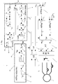
- the stator 1 of a brushless electric machine for example a synchronous motor with permanent magnet rotor, is operated by a converter 2 operating on the basis of pulse width modulation (PWM) with a three-phase three-phase current.
- PWM pulse width modulation
- the two phase currents i 1 , i 2 are tapped or measured by the stator, which are mapped in a 3-to-2 phase transformation unit 3 to a stator-related, orthogonal ⁇ , ⁇ coordinate system.
- two ⁇ , ⁇ vector components i ⁇ , i ⁇ representing the stator current are generated and output to a second, downstream coordinate transformation unit 4.
- This is adapted to a coordinate transformation from the stator-related ⁇ , ⁇ coordinate system to the rotor-related d, q coordinate system with the output of the current longitudinal and Quervektorkomponenten i d , iq make.
- the longitudinal and transverse vector components i d , iq from the stator current are fed as actual values to the series current and cross-current regulators I d , I q for the setpoint / actual value comparison with corresponding longitudinal and cross- current setpoint values i dsoll , i qsoll .
- the longitudinal current setpoint input i dsoll is set to zero, while the cross-flow controller receives the setpoint input I qsoll from an upstream speed controller 5.
- a determined electrical angle ⁇ em is output from the tracking controller 6 and supplied to the second transformation unit 4 and to a third transformation unit 7 complementary thereto.
- the third transformation unit 7 further receives the preset of the current regulators I d, I q longitudinal and transverse voltage vector components u g, u q and forms this u ⁇ , u ⁇ in the stator- ⁇ , ⁇ coordinate system with the specified voltage vector components from.
- the latter voltage vector components are received by a downstream, 2-to-3-phase transformation unit 8, which converts the voltage specification into three phases u 1 , u 2 , u 3 corresponding to the three-phase system for the downstream converter 2.
- FIG. 1 is the tracking controller 6 upstream of a motor modeling module 9.
- This has input interfaces 10 for the determined rotational speed ⁇ em , 11 for the measured longitudinal and transverse currents i d , iq and 12 mapped into the d, q coordinate system for the longitudinal and transverse voltages u d given in the d, q coordinate system , u q up.
- the modeling module 9 has a first output interface 13 for the longitudinal voltage deviation ⁇ u d and a second output interface 14 for the transverse voltage deviation ⁇ u q .
Priority Applications (7)
| Application Number | Priority Date | Filing Date | Title |
|---|---|---|---|
| EP07113231A EP2019482B1 (fr) | 2007-07-26 | 2007-07-26 | Système destiné au calcul de l'emplacement et de la vitesse pour un rotor à aimant permanent d'un moteur électrique |
| DE502007003311T DE502007003311D1 (de) | 2007-07-26 | 2007-07-26 | System zur Lage- und Geschwindigkeitsermittlung bei einem Permanentmagnet-Läufer einer elektrischen Maschine |
| AT07113231T ATE463073T1 (de) | 2007-07-26 | 2007-07-26 | System zur lage- und geschwindigkeitsermittlung bei einem permanentmagnet-läufer einer elektrischen maschine |
| DE202008009574U DE202008009574U1 (de) | 2007-07-26 | 2008-07-16 | System zur Lage- und Geschwindigkeitsermittlung bei einem Permanentmagnet-Läufer einer elektrischen Maschine |
| US12/177,182 US7999498B2 (en) | 2007-07-26 | 2008-07-22 | System for estimation of position and speed in a permanent magnet rotor of an electrical motor |
| CN2008101443425A CN101399514B (zh) | 2007-07-26 | 2008-07-25 | 用于检测电机永磁转子的位置和速度的系统 |
| JP2008191634A JP5501580B2 (ja) | 2007-07-26 | 2008-07-25 | 電気モータの永久磁石ロータにおける位置および速度の推定システム |
Applications Claiming Priority (1)
| Application Number | Priority Date | Filing Date | Title |
|---|---|---|---|
| EP07113231A EP2019482B1 (fr) | 2007-07-26 | 2007-07-26 | Système destiné au calcul de l'emplacement et de la vitesse pour un rotor à aimant permanent d'un moteur électrique |
Publications (2)
| Publication Number | Publication Date |
|---|---|
| EP2019482A1 true EP2019482A1 (fr) | 2009-01-28 |
| EP2019482B1 EP2019482B1 (fr) | 2010-03-31 |
Family
ID=38562827
Family Applications (1)
| Application Number | Title | Priority Date | Filing Date |
|---|---|---|---|
| EP07113231A Active EP2019482B1 (fr) | 2007-07-26 | 2007-07-26 | Système destiné au calcul de l'emplacement et de la vitesse pour un rotor à aimant permanent d'un moteur électrique |
Country Status (6)
| Country | Link |
|---|---|
| US (1) | US7999498B2 (fr) |
| EP (1) | EP2019482B1 (fr) |
| JP (1) | JP5501580B2 (fr) |
| CN (1) | CN101399514B (fr) |
| AT (1) | ATE463073T1 (fr) |
| DE (2) | DE502007003311D1 (fr) |
Cited By (2)
| Publication number | Priority date | Publication date | Assignee | Title |
|---|---|---|---|---|
| DE202012000091U1 (de) | 2012-01-05 | 2012-03-16 | Frank Mayer | Einrichtung zur Regelung einer Drehfeldmaschine an einem Direktumrichter bis Drehzahl Null |
| CN103346727A (zh) * | 2013-07-27 | 2013-10-09 | 湖北立锐机电有限公司 | 应用于 pmsm无位置控制的角度跟踪观测器及其实现方法 |
Families Citing this family (16)
| Publication number | Priority date | Publication date | Assignee | Title |
|---|---|---|---|---|
| US8248009B2 (en) | 2008-11-17 | 2012-08-21 | Rockwell Automation Technologies, Inc. | Motor controller having integrated communications configurations |
| US8375809B2 (en) * | 2010-03-02 | 2013-02-19 | Hamilton Sundstrand Corporation | Load monitoring for electromechanical systems |
| EP2421146B1 (fr) * | 2010-08-16 | 2015-02-11 | Baumüller Nürnberg GmbH | Dispositif et procédé d'identification des paramètres de référence magnéto-mécaniques d'un moteur synchrone triphasé sans utilisation d'encodeur de vitesse |
| GB2489434A (en) * | 2011-03-25 | 2012-10-03 | Technelec Ltd | Controlling an electrical machine with an observer |
| EP2552014A3 (fr) | 2011-07-28 | 2016-08-17 | Vestas Wind Systems A/S | Procédé de contrôle de position d'une machine électrique sans capteur |
| ES2673694T3 (es) | 2011-07-28 | 2018-06-25 | Vestas Wind Systems A/S | Método de control de posición sin sensor de una máquina eléctrica |
| CN102507189B (zh) * | 2011-09-23 | 2014-04-02 | 奇瑞汽车股份有限公司 | 混合动力电机转子位置的测试方法和测试系统 |
| US8823301B2 (en) | 2012-11-05 | 2014-09-02 | Whirlpool Corporation | Method and device for detecting rotor position in a permanent magnet synchronous motor-driven washing machine |
| US9722522B2 (en) | 2014-04-02 | 2017-08-01 | Canrig Drilling Technology Ltd. | Method for controlling torque in permanent magnet motor drives |
| US10655377B2 (en) | 2016-04-21 | 2020-05-19 | Westinghouse Air Brake Technologies Corporation | Method and system for detecting an obstruction of a passenger door |
| JP6661509B2 (ja) * | 2016-10-04 | 2020-03-11 | 日立オートモティブシステムズ株式会社 | ブラシレスモータの制御装置及び制御方法 |
| JP6757226B2 (ja) * | 2016-10-07 | 2020-09-16 | 株式会社マキタ | 電動工具 |
| GB2579633B (en) * | 2018-12-07 | 2023-02-01 | Zf Automotive Uk Ltd | A method of characterising a permanent magnet synchronous motor |
| CN112968643B (zh) * | 2021-02-01 | 2022-08-26 | 南京邮电大学 | 一种基于自适应扩展h∞滤波的无刷直流电机参数辨识方法 |
| CN115459663A (zh) | 2021-05-20 | 2022-12-09 | 台达电子工业股份有限公司 | 马达控制方法 |
| JP7362003B2 (ja) * | 2021-08-24 | 2023-10-16 | 三菱電機株式会社 | 回転機の制御装置 |
Citations (2)
| Publication number | Priority date | Publication date | Assignee | Title |
|---|---|---|---|---|
| JP2004015858A (ja) * | 2002-06-04 | 2004-01-15 | Meidensha Corp | Pmモータの位置センサレス制御方式 |
| US20050029972A1 (en) | 2003-05-19 | 2005-02-10 | Nobuyuki Imai | Control apparatus for brushless DC motor |
Family Cites Families (6)
| Publication number | Priority date | Publication date | Assignee | Title |
|---|---|---|---|---|
| JP3411878B2 (ja) * | 2000-03-06 | 2003-06-03 | 株式会社日立製作所 | 同期モータの回転子位置推定方法、位置センサレス制御方法及び制御装置 |
| JP3719910B2 (ja) * | 2000-05-30 | 2005-11-24 | 株式会社東芝 | モータ制御装置 |
| JP3651595B2 (ja) * | 2001-12-13 | 2005-05-25 | 株式会社東芝 | 洗濯機のインバータ装置及び洗濯乾燥機のインバータ装置 |
| JP3972124B2 (ja) * | 2002-07-10 | 2007-09-05 | 株式会社日立製作所 | 同期電動機の速度制御装置 |
| CN1767356A (zh) * | 2004-10-27 | 2006-05-03 | 乐金电子(天津)电器有限公司 | 直流无刷电机的速度控制装置及其方法 |
| CN100413207C (zh) * | 2006-11-17 | 2008-08-20 | 清华大学 | 一种异频供电永磁同步电动机矢量控制系统 |
-
2007
- 2007-07-26 EP EP07113231A patent/EP2019482B1/fr active Active
- 2007-07-26 AT AT07113231T patent/ATE463073T1/de active
- 2007-07-26 DE DE502007003311T patent/DE502007003311D1/de active Active
-
2008
- 2008-07-16 DE DE202008009574U patent/DE202008009574U1/de not_active Expired - Lifetime
- 2008-07-22 US US12/177,182 patent/US7999498B2/en active Active
- 2008-07-25 CN CN2008101443425A patent/CN101399514B/zh active Active
- 2008-07-25 JP JP2008191634A patent/JP5501580B2/ja not_active Expired - Fee Related
Patent Citations (2)
| Publication number | Priority date | Publication date | Assignee | Title |
|---|---|---|---|---|
| JP2004015858A (ja) * | 2002-06-04 | 2004-01-15 | Meidensha Corp | Pmモータの位置センサレス制御方式 |
| US20050029972A1 (en) | 2003-05-19 | 2005-02-10 | Nobuyuki Imai | Control apparatus for brushless DC motor |
Non-Patent Citations (1)
| Title |
|---|
| S. M. ABU-SHARKH; V. BARINBERG: "A new approach to rotor position estimation for a PM brushless motor drive", MEDITERRANEAN ELECTROTECHNICAL CONF., 1998, pages 1199 - 1203, XP000802006 |
Cited By (3)
| Publication number | Priority date | Publication date | Assignee | Title |
|---|---|---|---|---|
| DE202012000091U1 (de) | 2012-01-05 | 2012-03-16 | Frank Mayer | Einrichtung zur Regelung einer Drehfeldmaschine an einem Direktumrichter bis Drehzahl Null |
| CN103346727A (zh) * | 2013-07-27 | 2013-10-09 | 湖北立锐机电有限公司 | 应用于 pmsm无位置控制的角度跟踪观测器及其实现方法 |
| CN103346727B (zh) * | 2013-07-27 | 2016-01-20 | 湖北立锐机电有限公司 | 应用于pmsm无位置控制的角度跟踪观测器及其实现方法 |
Also Published As
| Publication number | Publication date |
|---|---|
| DE202008009574U1 (de) | 2009-03-12 |
| CN101399514A (zh) | 2009-04-01 |
| US7999498B2 (en) | 2011-08-16 |
| ATE463073T1 (de) | 2010-04-15 |
| JP5501580B2 (ja) | 2014-05-21 |
| US20090030645A1 (en) | 2009-01-29 |
| JP2009033963A (ja) | 2009-02-12 |
| CN101399514B (zh) | 2012-09-05 |
| DE502007003311D1 (de) | 2010-05-12 |
| EP2019482B1 (fr) | 2010-03-31 |
Similar Documents
| Publication | Publication Date | Title |
|---|---|---|
| EP2019482B1 (fr) | Système destiné au calcul de l'emplacement et de la vitesse pour un rotor à aimant permanent d'un moteur électrique | |
| DE60024222T2 (de) | Verfahren zur Schätzung der Rotorlage eines Synchronmotors, Verfahren zur Steuerung eines sensorlosen Synchronmotors und eine Steuerung für einen Synchronmotor | |
| DE60224021T2 (de) | Steuergerät für einen Elektromotor | |
| DE102007061905B4 (de) | Hochansprechende Permanentmagnetmotorsteuerung | |
| EP1985007B1 (fr) | Procede et dispositif de fonctionnement d'une machine synchrone | |
| DE10111795B4 (de) | Vektorsteuerungsverfahren für einen Reluktanz-Synchronmotor | |
| DE112008003590B4 (de) | Magnetpolpositions-Schätzverfahren für einen AC-Synchronmotor | |
| EP2226929B1 (fr) | Système de surveillance de la plausibilité pour des mesures de mouvements sur un dispositif d'entraînement électrique | |
| EP0127158B1 (fr) | Procédé et appareillage pour la détermination du vecteur de flux d'une machine à champ tournant d'après le courant stator et la tension stator et utilisation de ceux-ci | |
| DE10255890A1 (de) | Motoranormalitäts-Detektionsgerät und elektrisches Servolenksteuersystem | |
| DE10206410A1 (de) | Rotorwinkel-Erfassungsvorrichtung für bürstenlose Gleichstrommotoren | |
| DE112010001465T5 (de) | Wechselstrommotor-Steuervorrichtung und Wechselstrommotor-Treibersystem | |
| DE112004002619T5 (de) | Motorregelanordnung | |
| DE112012007011T5 (de) | Synchronmotor-Steuervorrichtung | |
| DE102016109777A1 (de) | Entwurf einer Motorregelung mit Anti-Windup und Spannungssättigung für eine elektrische Servolenkung | |
| DE102018130129A1 (de) | Controller-Anti-Windup für synchrone Permanentmagnetmaschinen | |
| DE112020005654T5 (de) | Motorantriebseinrichtung, ausseneinheit einer klimaanlage, die diese enthält, undmotorantriebssteuerverfahren | |
| EP2144362B1 (fr) | Procédé et agencement pour l'observation de la vitesse d'entraînement d'un rotor à aimant permanent dans un circuit d'entraînement | |
| EP2026461A2 (fr) | Procédé de régulation sans capteur d'un moteur à courant triphasé | |
| EP0771067A1 (fr) | Procédé et dispositif pour la régulation d'une machine à champ tournant, par l'orientation du champ | |
| DE102020130220A1 (de) | Versorgungsstrommanagement unter spannungsgesättigter Motorstromsteuerung | |
| DE102019116339B4 (de) | Motoransteuervorrichtung | |
| DE102008007100A1 (de) | Verfahren und Vorrichtung zur Stromregelung oder Momentenregelung | |
| DE102008045622B4 (de) | Verfahren zur Adaption einer Polradorientierung einer nicht linearen, geberlosen, permanenterregten Synchromaschine | |
| DE112018008190T5 (de) | Steuervorrichtung für eine rotierende Maschine und Steuervorrichtung eines elektrischen Fahrzeugs |
Legal Events
| Date | Code | Title | Description |
|---|---|---|---|
| PUAI | Public reference made under article 153(3) epc to a published international application that has entered the european phase |
Free format text: ORIGINAL CODE: 0009012 |
|
| AK | Designated contracting states |
Kind code of ref document: A1 Designated state(s): AT BE BG CH CY CZ DE DK EE ES FI FR GB GR HU IE IS IT LI LT LU LV MC MT NL PL PT RO SE SI SK TR |
|
| AX | Request for extension of the european patent |
Extension state: AL BA HR MK RS |
|
| 17P | Request for examination filed |
Effective date: 20090605 |
|
| GRAP | Despatch of communication of intention to grant a patent |
Free format text: ORIGINAL CODE: EPIDOSNIGR1 |
|
| AKX | Designation fees paid |
Designated state(s): AT BE BG CH CY CZ DE DK EE ES FI FR GB GR HU IE IS IT LI LT LU LV MC MT NL PL PT RO SE SI SK TR |
|
| GRAS | Grant fee paid |
Free format text: ORIGINAL CODE: EPIDOSNIGR3 |
|
| GRAA | (expected) grant |
Free format text: ORIGINAL CODE: 0009210 |
|
| AK | Designated contracting states |
Kind code of ref document: B1 Designated state(s): AT BE BG CH CY CZ DE DK EE ES FI FR GB GR HU IE IS IT LI LT LU LV MC MT NL PL PT RO SE SI SK TR |
|
| REG | Reference to a national code |
Ref country code: CH Ref legal event code: EP Ref country code: GB Ref legal event code: FG4D Free format text: NOT ENGLISH |
|
| REG | Reference to a national code |
Ref country code: IE Ref legal event code: FG4D |
|
| REF | Corresponds to: |
Ref document number: 502007003311 Country of ref document: DE Date of ref document: 20100512 Kind code of ref document: P |
|
| REG | Reference to a national code |
Ref country code: NL Ref legal event code: T3 |
|
| PG25 | Lapsed in a contracting state [announced via postgrant information from national office to epo] |
Ref country code: LT Free format text: LAPSE BECAUSE OF FAILURE TO SUBMIT A TRANSLATION OF THE DESCRIPTION OR TO PAY THE FEE WITHIN THE PRESCRIBED TIME-LIMIT Effective date: 20100331 |
|
| REG | Reference to a national code |
Ref country code: CH Ref legal event code: NV Representative=s name: SCHNEIDER FELDMANN AG PATENT- UND MARKENANWAELTE |
|
| LTIE | Lt: invalidation of european patent or patent extension |
Effective date: 20100331 |
|
| PG25 | Lapsed in a contracting state [announced via postgrant information from national office to epo] |
Ref country code: FI Free format text: LAPSE BECAUSE OF FAILURE TO SUBMIT A TRANSLATION OF THE DESCRIPTION OR TO PAY THE FEE WITHIN THE PRESCRIBED TIME-LIMIT Effective date: 20100331 Ref country code: LV Free format text: LAPSE BECAUSE OF FAILURE TO SUBMIT A TRANSLATION OF THE DESCRIPTION OR TO PAY THE FEE WITHIN THE PRESCRIBED TIME-LIMIT Effective date: 20100331 Ref country code: SI Free format text: LAPSE BECAUSE OF FAILURE TO SUBMIT A TRANSLATION OF THE DESCRIPTION OR TO PAY THE FEE WITHIN THE PRESCRIBED TIME-LIMIT Effective date: 20100331 Ref country code: PL Free format text: LAPSE BECAUSE OF FAILURE TO SUBMIT A TRANSLATION OF THE DESCRIPTION OR TO PAY THE FEE WITHIN THE PRESCRIBED TIME-LIMIT Effective date: 20100331 |
|
| REG | Reference to a national code |
Ref country code: IE Ref legal event code: FD4D |
|
| PG25 | Lapsed in a contracting state [announced via postgrant information from national office to epo] |
Ref country code: SE Free format text: LAPSE BECAUSE OF FAILURE TO SUBMIT A TRANSLATION OF THE DESCRIPTION OR TO PAY THE FEE WITHIN THE PRESCRIBED TIME-LIMIT Effective date: 20100331 Ref country code: CY Free format text: LAPSE BECAUSE OF FAILURE TO SUBMIT A TRANSLATION OF THE DESCRIPTION OR TO PAY THE FEE WITHIN THE PRESCRIBED TIME-LIMIT Effective date: 20100331 Ref country code: EE Free format text: LAPSE BECAUSE OF FAILURE TO SUBMIT A TRANSLATION OF THE DESCRIPTION OR TO PAY THE FEE WITHIN THE PRESCRIBED TIME-LIMIT Effective date: 20100331 Ref country code: ES Free format text: LAPSE BECAUSE OF FAILURE TO SUBMIT A TRANSLATION OF THE DESCRIPTION OR TO PAY THE FEE WITHIN THE PRESCRIBED TIME-LIMIT Effective date: 20100712 Ref country code: RO Free format text: LAPSE BECAUSE OF FAILURE TO SUBMIT A TRANSLATION OF THE DESCRIPTION OR TO PAY THE FEE WITHIN THE PRESCRIBED TIME-LIMIT Effective date: 20100331 |
|
| PG25 | Lapsed in a contracting state [announced via postgrant information from national office to epo] |
Ref country code: IS Free format text: LAPSE BECAUSE OF FAILURE TO SUBMIT A TRANSLATION OF THE DESCRIPTION OR TO PAY THE FEE WITHIN THE PRESCRIBED TIME-LIMIT Effective date: 20100731 Ref country code: CZ Free format text: LAPSE BECAUSE OF FAILURE TO SUBMIT A TRANSLATION OF THE DESCRIPTION OR TO PAY THE FEE WITHIN THE PRESCRIBED TIME-LIMIT Effective date: 20100331 Ref country code: SK Free format text: LAPSE BECAUSE OF FAILURE TO SUBMIT A TRANSLATION OF THE DESCRIPTION OR TO PAY THE FEE WITHIN THE PRESCRIBED TIME-LIMIT Effective date: 20100331 |
|
| BERE | Be: lapsed |
Owner name: BAUMULLER NURNBERG G.M.B.H. Effective date: 20100731 |
|
| PG25 | Lapsed in a contracting state [announced via postgrant information from national office to epo] |
Ref country code: DK Free format text: LAPSE BECAUSE OF FAILURE TO SUBMIT A TRANSLATION OF THE DESCRIPTION OR TO PAY THE FEE WITHIN THE PRESCRIBED TIME-LIMIT Effective date: 20100331 Ref country code: IE Free format text: LAPSE BECAUSE OF FAILURE TO SUBMIT A TRANSLATION OF THE DESCRIPTION OR TO PAY THE FEE WITHIN THE PRESCRIBED TIME-LIMIT Effective date: 20100331 Ref country code: PT Free format text: LAPSE BECAUSE OF FAILURE TO SUBMIT A TRANSLATION OF THE DESCRIPTION OR TO PAY THE FEE WITHIN THE PRESCRIBED TIME-LIMIT Effective date: 20100802 |
|
| PLBE | No opposition filed within time limit |
Free format text: ORIGINAL CODE: 0009261 |
|
| STAA | Information on the status of an ep patent application or granted ep patent |
Free format text: STATUS: NO OPPOSITION FILED WITHIN TIME LIMIT |
|
| PG25 | Lapsed in a contracting state [announced via postgrant information from national office to epo] |
Ref country code: MC Free format text: LAPSE BECAUSE OF NON-PAYMENT OF DUE FEES Effective date: 20100731 |
|
| 26N | No opposition filed |
Effective date: 20110104 |
|
| PG25 | Lapsed in a contracting state [announced via postgrant information from national office to epo] |
Ref country code: BE Free format text: LAPSE BECAUSE OF NON-PAYMENT OF DUE FEES Effective date: 20100731 |
|
| PG25 | Lapsed in a contracting state [announced via postgrant information from national office to epo] |
Ref country code: MT Free format text: LAPSE BECAUSE OF FAILURE TO SUBMIT A TRANSLATION OF THE DESCRIPTION OR TO PAY THE FEE WITHIN THE PRESCRIBED TIME-LIMIT Effective date: 20100331 |
|
| PG25 | Lapsed in a contracting state [announced via postgrant information from national office to epo] |
Ref country code: LU Free format text: LAPSE BECAUSE OF NON-PAYMENT OF DUE FEES Effective date: 20100726 Ref country code: BG Free format text: LAPSE BECAUSE OF FAILURE TO SUBMIT A TRANSLATION OF THE DESCRIPTION OR TO PAY THE FEE WITHIN THE PRESCRIBED TIME-LIMIT Effective date: 20100331 Ref country code: HU Free format text: LAPSE BECAUSE OF FAILURE TO SUBMIT A TRANSLATION OF THE DESCRIPTION OR TO PAY THE FEE WITHIN THE PRESCRIBED TIME-LIMIT Effective date: 20101001 |
|
| PG25 | Lapsed in a contracting state [announced via postgrant information from national office to epo] |
Ref country code: TR Free format text: LAPSE BECAUSE OF FAILURE TO SUBMIT A TRANSLATION OF THE DESCRIPTION OR TO PAY THE FEE WITHIN THE PRESCRIBED TIME-LIMIT Effective date: 20100331 |
|
| PG25 | Lapsed in a contracting state [announced via postgrant information from national office to epo] |
Ref country code: BG Free format text: LAPSE BECAUSE OF FAILURE TO SUBMIT A TRANSLATION OF THE DESCRIPTION OR TO PAY THE FEE WITHIN THE PRESCRIBED TIME-LIMIT Effective date: 20100630 |
|
| PGFP | Annual fee paid to national office [announced via postgrant information from national office to epo] |
Ref country code: NL Payment date: 20130722 Year of fee payment: 7 |
|
| PG25 | Lapsed in a contracting state [announced via postgrant information from national office to epo] |
Ref country code: GR Free format text: LAPSE BECAUSE OF FAILURE TO SUBMIT A TRANSLATION OF THE DESCRIPTION OR TO PAY THE FEE WITHIN THE PRESCRIBED TIME-LIMIT Effective date: 20100331 |
|
| REG | Reference to a national code |
Ref country code: NL Ref legal event code: V1 Effective date: 20150201 |
|
| PG25 | Lapsed in a contracting state [announced via postgrant information from national office to epo] |
Ref country code: NL Free format text: LAPSE BECAUSE OF NON-PAYMENT OF DUE FEES Effective date: 20150201 |
|
| REG | Reference to a national code |
Ref country code: FR Ref legal event code: PLFP Year of fee payment: 10 |
|
| REG | Reference to a national code |
Ref country code: FR Ref legal event code: PLFP Year of fee payment: 11 |
|
| REG | Reference to a national code |
Ref country code: FR Ref legal event code: PLFP Year of fee payment: 12 |
|
| REG | Reference to a national code |
Ref country code: CH Ref legal event code: PFA Owner name: BAUMUELLER NUERNBERG GMBH, DE Free format text: FORMER OWNER: BAUMUELLER NUERNBERG GMBH, DE |
|
| PGFP | Annual fee paid to national office [announced via postgrant information from national office to epo] |
Ref country code: IT Payment date: 20230731 Year of fee payment: 17 Ref country code: GB Payment date: 20230724 Year of fee payment: 17 Ref country code: CH Payment date: 20230802 Year of fee payment: 17 Ref country code: AT Payment date: 20230718 Year of fee payment: 17 |
|
| PGFP | Annual fee paid to national office [announced via postgrant information from national office to epo] |
Ref country code: FR Payment date: 20230724 Year of fee payment: 17 Ref country code: DE Payment date: 20230720 Year of fee payment: 17 |