EP2018741B1 - Kontaktlose programmierung und prüfung von speicherelementen - Google Patents
Kontaktlose programmierung und prüfung von speicherelementen Download PDFInfo
- Publication number
- EP2018741B1 EP2018741B1 EP06744702A EP06744702A EP2018741B1 EP 2018741 B1 EP2018741 B1 EP 2018741B1 EP 06744702 A EP06744702 A EP 06744702A EP 06744702 A EP06744702 A EP 06744702A EP 2018741 B1 EP2018741 B1 EP 2018741B1
- Authority
- EP
- European Patent Office
- Prior art keywords
- programming
- data
- short range
- communications interface
- range communications
- Prior art date
- Legal status (The legal status is an assumption and is not a legal conclusion. Google has not performed a legal analysis and makes no representation as to the accuracy of the status listed.)
- Not-in-force
Links
Images


Classifications
-
- H—ELECTRICITY
- H04—ELECTRIC COMMUNICATION TECHNIQUE
- H04L—TRANSMISSION OF DIGITAL INFORMATION, e.g. TELEGRAPHIC COMMUNICATION
- H04L67/00—Network arrangements or protocols for supporting network services or applications
- H04L67/01—Protocols
- H04L67/12—Protocols specially adapted for proprietary or special-purpose networking environments, e.g. medical networks, sensor networks, networks in vehicles or remote metering networks
- H04L67/125—Protocols specially adapted for proprietary or special-purpose networking environments, e.g. medical networks, sensor networks, networks in vehicles or remote metering networks involving control of end-device applications over a network
-
- H—ELECTRICITY
- H04—ELECTRIC COMMUNICATION TECHNIQUE
- H04L—TRANSMISSION OF DIGITAL INFORMATION, e.g. TELEGRAPHIC COMMUNICATION
- H04L12/00—Data switching networks
- H04L12/28—Data switching networks characterised by path configuration, e.g. LAN [Local Area Networks] or WAN [Wide Area Networks]
-
- G—PHYSICS
- G06—COMPUTING OR CALCULATING; COUNTING
- G06F—ELECTRIC DIGITAL DATA PROCESSING
- G06F8/00—Arrangements for software engineering
- G06F8/60—Software deployment
- G06F8/61—Installation
-
- G—PHYSICS
- G06—COMPUTING OR CALCULATING; COUNTING
- G06F—ELECTRIC DIGITAL DATA PROCESSING
- G06F8/00—Arrangements for software engineering
- G06F8/60—Software deployment
- G06F8/61—Installation
- G06F8/64—Retargetable
-
- G—PHYSICS
- G06—COMPUTING OR CALCULATING; COUNTING
- G06F—ELECTRIC DIGITAL DATA PROCESSING
- G06F8/00—Arrangements for software engineering
- G06F8/60—Software deployment
- G06F8/65—Updates
- G06F8/654—Updates using techniques specially adapted for alterable solid state memories, e.g. for EEPROM or flash memories
-
- H—ELECTRICITY
- H04—ELECTRIC COMMUNICATION TECHNIQUE
- H04B—TRANSMISSION
- H04B7/00—Radio transmission systems, i.e. using radiation field
- H04B7/24—Radio transmission systems, i.e. using radiation field for communication between two or more posts
-
- H—ELECTRICITY
- H04—ELECTRIC COMMUNICATION TECHNIQUE
- H04L—TRANSMISSION OF DIGITAL INFORMATION, e.g. TELEGRAPHIC COMMUNICATION
- H04L67/00—Network arrangements or protocols for supporting network services or applications
- H04L67/34—Network arrangements or protocols for supporting network services or applications involving the movement of software or configuration parameters
-
- H—ELECTRICITY
- H04—ELECTRIC COMMUNICATION TECHNIQUE
- H04M—TELEPHONIC COMMUNICATION
- H04M1/00—Substation equipment, e.g. for use by subscribers
- H04M1/72—Mobile telephones; Cordless telephones, i.e. devices for establishing wireless links to base stations without route selection
- H04M1/724—User interfaces specially adapted for cordless or mobile telephones
- H04M1/72403—User interfaces specially adapted for cordless or mobile telephones with means for local support of applications that increase the functionality
- H04M1/72406—User interfaces specially adapted for cordless or mobile telephones with means for local support of applications that increase the functionality by software upgrading or downloading
-
- H—ELECTRICITY
- H04—ELECTRIC COMMUNICATION TECHNIQUE
- H04W—WIRELESS COMMUNICATION NETWORKS
- H04W8/00—Network data management
- H04W8/22—Processing or transfer of terminal data, e.g. status or physical capabilities
- H04W8/24—Transfer of terminal data
- H04W8/245—Transfer of terminal data from a network towards a terminal
-
- H—ELECTRICITY
- H04—ELECTRIC COMMUNICATION TECHNIQUE
- H04M—TELEPHONIC COMMUNICATION
- H04M1/00—Substation equipment, e.g. for use by subscribers
- H04M1/24—Arrangements for testing
-
- H—ELECTRICITY
- H04—ELECTRIC COMMUNICATION TECHNIQUE
- H04M—TELEPHONIC COMMUNICATION
- H04M1/00—Substation equipment, e.g. for use by subscribers
- H04M1/72—Mobile telephones; Cordless telephones, i.e. devices for establishing wireless links to base stations without route selection
- H04M1/724—User interfaces specially adapted for cordless or mobile telephones
- H04M1/72403—User interfaces specially adapted for cordless or mobile telephones with means for local support of applications that increase the functionality
- H04M1/72409—User interfaces specially adapted for cordless or mobile telephones with means for local support of applications that increase the functionality by interfacing with external accessories
- H04M1/72412—User interfaces specially adapted for cordless or mobile telephones with means for local support of applications that increase the functionality by interfacing with external accessories using two-way short-range wireless interfaces
Definitions
- This invention is related to methods and devices for performing programming, configuring, debugging and/or testing of memory components in a contactless manner.
- the manufacturing of a number of modem devices including electronic equipment, e.g. mobile terminals etc. requires permanent and/or temporary programming of memory components with certain information. This includes informations like firmware, operating system, application software, market specific configuration data, logistics data and media content
- testing/debugging is usually performed using the JTAG (Joint Test Action Group) system.
- Product debugging via JTAG is typically done by connecting a physical four/five-pin interface.
- a method for contactless programming of a memory element of an electronic device having a wireless short range communications interface comprising:
- the method according to the invention enables the replacement of direct physical connections for the programming of memory modules, e.g. during manufacturing of an electronic device or component This provides improved flexibility, as the programming can be performed at any time and at any location within the manufacturing and logistics chain.
- the reduction or even omission of physical contacts can also improve immunity of the memory modules against electrostatic discharges.
- the wireless interface replacing the conventional direct connections can also be used later on for debugging/testing purposes, and even in the logistics channels for altering system software or like, without opening the package.
- the contactless interface allows also recovering user data from a device in service or by user using RFID readers. Recovering is usually done when the user has purchased a new device and the old device is not operating normally. This malfunction is usually caused by some damaged component other than memory, e.g. if physical interface such as a pad connection is damaged by corrosion caused by humidity, and/or the program memory or file system is corrupted. Particularly embodiments wherein the power for performing this "data saving" procedure can be powered by the interrogation signal alone provide an improved reliability.
- Media content can for example comprise pre-programmed convent like screensavers, background images, themes, sounds, software download links and the like.
- Configuration data can e.g. comprise configuration data relating to a specific mobile service provider, manufacturer, distributor, corporate IT specific configuration, device clock settings, end user, or like.
- Logistic data can comprise delivery chain information such as location, temperature, humidity.
- the invention can also be used for replacing the shock indicator stickers indicating if a shipped product was exposed to mechanical shock or like. If a sensor like a mechanical shock sensor, temperature sensor or humidity sensor is provided within the electronic device, it is possible to determine if anywhere in the logistic chain the device was subjected to harmful conditions provide a corresponding indication. As the invention enables to provide such an arrangement within the product itself this can prevent any manipulation, e.g. by the shipping company.
- a method for contactless programming of a memory element of an electronic device having a wireless short range communications interface comprising:
- the inventive method inter alia enables to "customize" electronic devices easily, by selecting the programming data based on the actual hardware configuration.
- the hardware configuration may e.g. include information about the camera type within a mobile phone, if a Bluetooth chip is present and other device-specific configuration data.
- the programming data can then be selected correspondingly.
- said programming data further include programming routines, and wherein said programming step is performed according to said programming routines.
- said programming routines e.g. the flashing software
- the actual programming routines can be provided, thus improving the flexibility, as the programming routines do not need to be provided beforehand and in "static" conventional manner.
- This embodiment inter alia enables to "backup" data from a defective electronic device through the wireless short range communications interface.
- the information within the device can be saved with the present invention.
- the wireless short range communications interface e.g. RFID
- the wireless short range communications interface is adapted to provide enough power to perform the reading out of data.
- the method described above is used in manufacturing, logistics or service procedures of said electronic device. Replacing wired connections in manufacturing, logistics and service procedures in this manneroffers an improved flexibility over conventional wire-based connections, for example in device replacement situations.
- the manufacturing comprises an assembly step of hardware components including said memory element, and wherein said method for programming said memory element is performed before, during or after said assembly step.
- a computer program product comprising program code means stored on a computer readable medium for carrying out the method described above when said program product is run on a computer or network device.
- a device for contactless programming of a memory element of an electronic device having a wireless short range communications interface comprising:
- an electronic device comprising:
- said programming data further include programming routines
- said controller is further adapted for extracting said programming routines from said programming data and perform said programming according to said programming routines.
- said controller is adapted for performing a testing procedure on said memory element and/or said electronic device, and for transmitting results of said testing.
- said wireless short range communication interface is adapted for providing power to said controller for enabling operation thereof, The power being supplied to said wireless short range communication interface by an interrogation signal.
- said controller is adapted for denying further programming access via said short range communications interface to said memory element.
- said wireless short range communications interface comprises a detachable antenna.
- said wireless short range communications interface is adapted to be disabled, and said controller is adapted for disabling said wireless short range communications interface subsequent to a programming of said memory element.
- said IC interfaces or subsystems connected to said interfaces are adapted to be disabled, and said controller is adapted for performing said disabling of said IC interfaces or subsystems connected to said IC interface.
- said memory element is an electrically programmable memory component, selected e.g. from the group comprising:
- said wireless short range communications interface is an RFID interface.
- An RFID system generally comprises an interrogator (or sometimes called a reader) and one or more tags (or sometime called transponders).
- the RFID interrogator may also act as a writer.
- the power which is needed to operate and read/write data to/from these tags is transferred from the interrogator to the tag via electromagnetic fields; therefore the tag can operate without its own power supply (e.g. battery).
- This kind of a system is called a passive RFID system and it usually requires a fairly constant power transfer from the interrogator.
- Another option is the use of semi-passive tags wherein power is supplied from its own power source, but the electromagnetic field generated by the interrogator is used for transferring data from the tag to the interrogator.
- a third category comprises active RFID systems, wherein a tag uses its own power supply to power the chip and also for communication back to the interrogator.
- RFID systems can be divided into two categories: near-field and far-field systems.
- near-field systems In the near-field systems the distance is typically less than the wavelength/(2*pi) and in the far-field systems the reading distance is greater than that.
- near-field systems typically inductive coupling is used, and in far-field system backscattering coupling is used.
- Far-field systems are usually operating at higher frequencies than near-field systems.
- Backscattering RFID systems operating at microwave frequencies (above 1 GHz) are usually using radar technology where electromagnetic waves are reflected by objects with dimensions that are larger than half of the wavelength. By changing antenna properties in the tag the properties of the reflected signal can be modified. This enables a communication from the tag back to the interrogator.
- usually a continuous carrier wave is used for communication, although in basic radar short pulses are utilized.
- the reflected signal must be separated from the carrier signal in the interrogator.
- the most critical aspect is how fast and reliably the interrogator can write data to the tag.
- the power required for reading data from passive tags is much higher than the power needed to write something to a tag, due to the fact that the link loss is doubled.
- the link loss of 1 meter is roughly -40 dB in one direction (writing) and -80 dB in two directions (reading).
- the writing speed can be much higher than the reading speed, at least over long distances.
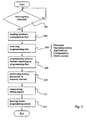
- Fig. 1 shows steps of an exemplary embodiment of the method of the present invention.
- step 102 it is detected if there is a wireless short range interface present, that is, an interrogation step is performed. This step is repeated until a wireless short range interface is detected to be in range.
- Responsive to the interrogation data indicating the hardware configuration of an electronic device is received in step 104, for being enabled to determine the actual type of device comprising the wireless interface.
- Step 104 may optionally be preceded by an initial authentication step, wherein the device is being authenticated. This could for example be advantageous if products having the same hardware shall be customized in a certain way, e.g. based on some serial number. Also this is suitable for programming a variety of different devices with different hardware configurations on the same production line.
- a mobile phone can be pre-programmed by the invention with different language versions of its user interface (English, German, French etc.).
- the wireless interface could then provide the information which language version is desired for the current mobile phone to be programmed, e.g. based on a serial number of a specific hardware component.
- Another example could be a line of mobile phones or PDAs or like, wherein some components are only optional. Components like a WLAN or Bluetooth transceiver or a camera may only be present in certain devices, although the rest of the hardware is identical. In this case the invention enables to program memory elements of such electronic devices only with drivers and/or related application software which are required in that particular model. In a device having a camera the image capture/manipulation/viewer drivers/programs are required, while they would only waste precious memory space otherwise.
- step 104 an optional testing step (not shown) may be performed, wherein verification is made that all HW components in the system are working correctly. I.e. for example if the FLASH memory is connected correctly to the application ASIC, if all PINs are functioning in the right way etc.
- This step may also be performed by having temporary software uploaded to the device that will take care of doing such checks. This software could then be removed again, that is, overwritten by the actual programming data.
- the method proceeds to step 106 where programming data are being selected according to the hardware configuration.
- programming data in the context of the present invention may comprise e.g.
- programming data shall not be restricted only to the actual payload data
- the programming data do furthermore include the required programming/flashing algorithms as well, which are the basis for being enabled to program the payload data. This provides an enormous flexibility, as these flashing algorithms must not be present in the device beforehand.
- step 108 the selected programming data are sent to the electronic device, and the process of this embodiment terminates.
- step 204 Responsive to a detection of an interrogation in step 202 data indicating the hardware configuration of an electronic device are sent in step 204, to be received at the sending end (corresponding to step 104 in fig. 1 ).
- Step 204 may optionally be preceded by an initial authentication step, wherein the originator of the interrogation signal is being authenticated.
- programming data are received in step 206 (corresponding to step 108 in fig. 1 ).
- step 208 a memory element is programmed according to the received programming data.
- step 210 a testing procedure is performed on the memory element. Results from this testing are transmitted in step 212. Finally, any further programming access to the memory element can be denied, in step 214.
- the programming of memory modules within the device to be produced is performed in accordance with the programming data. That is, e.g. using the included programming algorithms, and in all cases the included payload data.
- the memory module can be tested/debugged e.g. using the very common JTAG interface that is part of many of such modules.
- the results of this testing/debugging procedure are then sent to analysis equipment, again using the wireless interface, in step 212. In this manner the testing/debugging is not dependent of physical contact with such analysis equipment, making this procedure more flexible, as it can now be performed anywhere and anytime that is suitable.
- Conventional methods require the testing to be performed in a testing site comprising the required apparatus for establishing physical contact with e.g. test pins on the memory module.
- step 214 which is also optional, further programming access to the flashed and tested memory module is denied. It should be apparent that this improves the security of the process, that is, prevents any unwanted tampering with the finalized memory module. Denying further access can be achieved by different means, will also be detailed later on. For example it is possible to simply detach the antenna of the wireless interface, or disable it by means of short circuiting or destroying of the antenna structure through soldering, laser cutting or the like.
- An optional step to be performed instead of the above mentioned step 214 may include a security check for any received programming data before performing the programming with that data. This step would not require disabling the antenna in all use cases. Verification of the downloaded SW can be done by known SW authentication and security systems.
- step 220 receives an interrogation signal in step 220.
- the signal may be used to provide the electrical power for actually performing the programming procedures explained above (step 222). This is particularly advantageous if an electronic device of a user has stopped working properly, e.g. the connection with the energy supply, Li-Ion battery or like, is broken.
- this embodiment it may then still be possible to read out some personal data of the user, like the phonebook content This reading out is performed in step 224, and the read out data can then be transmitted in step 226, enabling the user to save his data.
- the interrogation signal is to be understood in a broad sense, that is, it may be replaced by any other electromagnetic signal which is sufficient to provide enough power to the device.
- other electromagnetic emitters may be used, like a WLAN transceiver or other radio device.
- the power can be provided by radiation as well as inductively. Providing the power in this wireless manner can be used in conjunction with other embodiments.
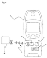
- Fig. 4 depicts an exemplary embodiment of a memory module according to the present invention.
- a mobile phone 2 comprising a memory module according to the invention.
- the memory module comprises an RFID interface 4, a memory component 8, and a controller 6 connected with the wireless interface 4 and memory component 8.
- the memory module built into the device 2 can be programmed / flashed via the RFID interface 4.
- An RFID writer device 20 can send programming data (indicated by 12) to the RFID interface 4. This may include only payload data to be programmed into the memory component 8, or in alternative embodiments also the algorithms required for performing the programming operation. That is, the programming data 12 may include e.g. flashing algorithms enabling the controller 6 to program the memory component 8 according to the payload data also included within the programming data.
- the inventive memory module can be used in conjunction with any other device. It can further be programmed even before being integrated into the respective device.
- the RFID 4 interface disabled, e.g. by detaching the antenna, or by disconnecting the RFID interface 4 from the controller.
- a further programming access to the memory component 8 can be prevented, e.g. in order to avoid any unauthorized tampering with the data content of the memory component 8.
- This avoiding of unauthorized manipulation may in other embodiments also be performed by disabling IC interfaces (JAG, I 2 C, etc.), or by disabling subsystems connected to said IC interfaces.
- fig. 5 an embodiment of the RFID writer device 20 according to the invention is illustrated. It comprises a second wireless interface 22, a data storage 26 for storing programming data, and a controller 24 connected with the wireless interface 22 and the data storage 26.
- the components can be integrated into a single device as indicated by the dashed box.
- the data storage 26 can be an external data storage, e.g. a data bank connected through a network.
- the invention is related to a use of RAID technology to replace physical connections in R&D, mass manufacturing, logistics and maintenance/service phases.
- the major feature of the invention is to use RFID for flashing memory components and/or testing/debugging devices during manufacturing without the need to establish a physical contact.
- CMT component placement phase
- molding phase molding phase
- interconnection phase reflow, inkjet integrated
- the invention can be used to provide a connection to internal product interfaces such as JTAG, I 2 C, I/O pins, memory and data buses, CPU registers, cameras, display interfaces or interfaces for powering on I/O cells.
- internal product interfaces such as JTAG, I 2 C, I/O pins, memory and data buses, CPU registers, cameras, display interfaces or interfaces for powering on I/O cells.
- RFID interface which provides more flexibility- It also makes the manufacturing process more flexible as the flashing operation is not limited to a certain process step at a certain physical location.
- Another advantage to be obtained with the present invention can be an improved immunity against electrostatic discharges, in case physical connectors can be reduced or avoided altogether. Means for dealing with such electrostatic discharges could then be omitted, which can further improve the production process.
- One use case could be manufacturing of devices such as mobile phones, memory cards and SIM cards.
- the (external) RFID reader reads out device information, e.g. the type/model of the mobile phone to be produced, and then uploads data to the phone according to what is desired.
- This data can include firmware, operating system software, application software, default media content and the like.
- a major feature of the invention is to program the memory of a device during a manufacturing process or in logistics channels. In the following some examples of the process are given:
- the first option is that programming can be done before assembling the memory to the PWB.
- the (RFID) tag chip can be arranged inside the memory, as well as the antenna.
- Another option is that the antenna is integrated into the reel where the memory is delivered and thus the antenna is removed before assembly. In this case the memory cannot be re-flashed without physical contact if final devices do not include an antenna for the chip. If re-flashing via RFID is made impossible in this manner, security is improved.
- the procedure can be executed also after assembly, in logistics channels (without opening the package) and after purchase.
- the tag can be arranged inside the memory chip or integrated to some other chip that is capable of programming the memory.
- the antenna can be inside the memory chip, an external component or integrated into some other component.
- the antenna can be printed either into the silicon die package or it can be printed on the substrate.
- the RFID tag can be used only once to write data into the memory, and then it will be locked and flashing can only be done via a physical interface.
- the tag may get all or part of the necessary energy for example from a back-up battery, thus it can be a passive, semi-passive or active tag.
- RFID-WPD wireless programming and debugging subsystem
- RFID-WPD wireless programming and debugging subsystem
- the RFID-WPD subsystem detects the existence of the interfaces on the device.
- a combined RFID JTAG service will be established.
- the external control system can power on other chips on the device, read and write data using JTAG protocols on top of RFID radio protocols.
- the necessary power can be received via RFID interrogation signal, from main battery or some other power source.
- RFID JTAG connection service exists information about components on device is delivered to the external control system.
- the external control system delivers the required programming (e.g. flashing) algorithms to subsystem X and starts sending the payload data to be programmed.
- Subsystem X then starts programming memory components on the product. In this manner the need for having preliminary flashing algorithms on the device already is eliminated, enabling more flexibility and possibly reducing the cycle time in the production.
- RFID-WPD subsystem In a case where RFID-WPD subsystem is connected and integrated directly into memory chip direct access to memory blocks can be established via the combined RFID JTAG system or using some other interface on module.
- the RFID In addition to uploading the data to the memory, the RFID can be also be directly connected to the JTAG chain of an Application Specific Circuit (ASIC) to allow testing and/or programming of the functionality of the ASIC without physical contact to the chip.
- ASIC Application Specific Circuit
- the RFID technology for example can be a 13MHz RFID standard that can provide e.g. 424 Kbit of transfer rate, but may as well be a 2.45 GHz RFID standard, depending on which one is most suitable for the desired system characteristic. For example at higher frequencies more data rate is possible, but power transfer is more difficult.
- the RFID tag may be passive, semi-passive or active. Radio devices being part of the electronic device to be produced, such as GSM, WCDMA, CDMA, UWB, WLAN, can also be used for this purpose, i.e. for providing the electromagnetic energy to power the RFID tag, if they can be powered up during the process.
- the invention can also be applied to a device with an integrated RFID reader/communication module, that is, a device already having an integrated RFID interface, which is a likely feature of future mobile devices etc.
- Memory devices present within this electronic device e.g. mobile phone, can then be flashed according to the techniques presented in this invention.
- the device In order to provide the flashing, the device needs to have power that can be provided by an attached battery, e.g. the main battery of the mobile phone.
- the flashing may be a pre-process of the testing of the RFID interface or like, as this testing will require power anyway, the memory will be "cut off", e.g. disconnected from the RFID interface, such that no flashing of the device over the RFID interface can be performed anymore. It should be apparent that preventing further flashing of internal memory components of a device must be possible.
- the invention described above it not to be limited to mobile terminals or like.
- the invention can also be applied in connection with other types of products comprising an RFID interface, such as for example future cars or like having an RFID communication module for e.g. detecting a driver and/or mobile devices within the car for automatically adapting the car settings to correspond to the situation.
Landscapes
- Engineering & Computer Science (AREA)
- Software Systems (AREA)
- General Engineering & Computer Science (AREA)
- Theoretical Computer Science (AREA)
- Computer Networks & Wireless Communication (AREA)
- Signal Processing (AREA)
- Physics & Mathematics (AREA)
- General Physics & Mathematics (AREA)
- Health & Medical Sciences (AREA)
- Computing Systems (AREA)
- General Health & Medical Sciences (AREA)
- Medical Informatics (AREA)
- Computer Security & Cryptography (AREA)
- Databases & Information Systems (AREA)
- Human Computer Interaction (AREA)
- Mobile Radio Communication Systems (AREA)
- Read Only Memory (AREA)
- Tests Of Electronic Circuits (AREA)
- Test And Diagnosis Of Digital Computers (AREA)
Claims (25)
- Verfahren während der Herstellung einer elektronischen Vorrichtung (2), Folgendes umfassend:- Senden eines Abfragesignals, um Energie für eine passive funkbasierte kurzreichweitige Kommunikationsschnittstelle (4) einer elektronischen Vorrichtung (2) bereitzustellen, die ein Speicherelement (8) hat, das nicht programmiert wurde, und um bei der passiven funkbasierten kurzreichweitigen Kommunikationsschnittstelle (4) eine Antwort auf das Abfragesignal auszulösen;- Empfangen (104), in Reaktion auf das Abfragesignal, von Daten von der passiven funkbasierten kurzreichweitigen Kommunikationsschnittstelle, wobei die Daten wenigstens Information über eine Hardwarekonfiguration der elektronischen Vorrichtung (2) enthalten;- Auswählen (106) von Programmierdaten (12) für eine initiale Programmierung des nicht programmierten Speicherelements (8) basierend auf der Hardwarekonfiguration; und- Senden (108) der ausgewählten Programmierdaten (12), die für den Empfang durch die funkbasierte kurzreichweitige Kommunikationsschnittstelle (4) vorgesehen sind, um eine initiale Programmierung des nicht programmierten Speicherelements (8) auszuführen.
- Verfahren nach Anspruch 1, wobei die Programmierdaten (12) aus der Gruppe gewählt sind, die Folgendes umfasst:- Firmware;- Betriebssystem-Software;- Anwendungs-Software;- Logistikdaten;- Konfigurationsdaten; und- Medieninhalte.
- Verfahren während der Herstellung einer elektronischen Vorrichtung (2), Folgendes umfassend:- Empfangen eines Abfragesignals an einer passiven funkbasierten kurzreichweitigen Kommunikationsschnittstelle (4) einer elektronischen Vorrichtung (2), die ein Speicherelement (8) hat, das nicht programmiert wurde;- Senden (204), in Reaktion auf das Abfragesignal, von Daten über die passive funkbasierte kurzreichweitige Kommunikationsschnittstelle (4), wobei die Daten wenigstens Information über eine Hardwarekonfiguration der elektronischen Vorrichtung (2) enthalten;- Empfangen (206) von Programmierdaten (12) an der passiven funkbasierten kurzreichweitigen Kommunikationsschnittstelle (4); und- Ausführen einer initialen Programmierung (208) des nicht programmierten Speicherelements (8) entsprechend den Programmierdaten (12).
- Verfahren nach Anspruch 3, wobei die Programmierdaten (12) außerdem Programmierroutinen umfassen und wobei die Programmierung (208) entsprechend den Programmierroutinen ausgeführt wird.
- Verfahren nach Anspruch 3 oder 4, außerdem Folgendes umfassend:- Ausführen (210) einer Testprozedur auf dem Speicherelement (8) und/oder der elektronischen Vorrichtung (2); und- Senden (212) von Ergebnissen des Testvorgangs über die passive funkbasierte kurzreichweitige Kommunikationsschnittstelle (4).
- Verfahren nach einem der Ansprüche 3 bis 5, außerdem Folgendes umfassend:- Empfangen (220) eines Abfragesignals;- Auslesen (224) von Daten aus dem Speicherelement (8); und- Senden (226) der ausgelesenen Daten über die passive funkbasierte kurzreichweitige Kommunikationsschnittstelle (4);wobei das Auslesen (224) und das Senden (226) mit Energie ausgeführt werden, die durch das Abfragesignal zugeführt wurde.
- Verfahren nach einem der Ansprüche 3 bis 6, außerdem Folgendes umfassend:- Verweigern (214) weiterer Programmierzugriffe über die passive funkbasierte kurzreichweitige Kommunikationsschnittstelle (4) auf das Speicherelement (8).
- Verfahren nach Anspruch 7, wobei die passive funkbasierte kurzreichweitige Kommunikationsschnittstelle (4) eine Antenne umfasst und wobei das Verweigern (214) Folgendes umfasst:- Abschalten der Antenne.
- Verfahren nach Anspruch 7, wobei das Verweigern (214) Folgendes umfasst:- Abschalten der passiven funkbasierten kurzreichweitigen Kommunikationsschnittstelle (4).
- Verfahren nach Anspruch 7, wobei das Verweigern (214) Folgendes umfasst:- Abschalten von IC-Schnittstellen, die mit der passiven funkbasierten kurzreichweitigen Kommunikationsschnittstelle (4) verbunden sind; oder- Abschalten von Subsystemen, die mit den IC-Schnittstellen verbunden sind.
- Verfahren nach einem der vorhergehenden Ansprüche, das bei der Herstellung, der Logistik oder bei Servicevorgängen für die elektronische Vorrichtung (2) eingesetzt wird.
- Verfahren nach Anspruch 11, wobei die Herstellung der elektronischen Vorrichtung (2) den Zusammenbau von Hardwarekomponenten umfasst, die das Speicherelement (8) enthalten, und wobei das Verfahren vor, während oder nach dem Zusammenbau ausgeführt wird.
- Verfahren nach einem der Ansprüche 3 bis 12, wobei aus dem Abfragesignal Energie empfangen wird und wobei die vom Abfragesignal zugeführte Energie für das Senden, das Empfangen und die Programmierung verwendet wird.
- Computerprogrammprodukt, das ein Programmcodemittel umfasst, das auf einem computerlesbaren Medium gespeichert ist, um das Verfahren nach einem der Ansprüche 1 bis 13 auszuführen, wenn das Programmprodukt auf einem Computer oder einer Netzvorrichtung ausgeführt wird.
- Vorrichtung, Folgendes umfassend:- eine funkbasierte kurzreichweitige Kommunikationsschnittstelle (22);- einen Datenspeicher (26) zum Speichern von Programmierdaten (12);- einen Kontroller (24), der mit der funkbasierten kurzreichweitigen Kommunikationsschnittstelle (22) und dem Datenspeicher (26) verbunden ist;wobei der Kontroller (24) für Folgendes eingerichtet ist: das Senden eines Abfragesignals über die funk basierte kurzreichweitige Kommunikationsschnittstelle (22), um Energie für eine passive funkbasierte kurzreichweitige Kommunikationsschnittstelle (4) einer elektronischen Vorrichtung (2) bereitzustellen, die ein programmierbares Speicherelement (8) hat, das nicht programmiert wurde, das Auslösen einer Antwort auf das Abfragesignal bei der passiven funkbasierten kurzreichweitigen Kommunikationsschnittstelle (4), das Empfangen (104), in Reaktion auf das Abfragesignal, von Daten über die funkbasierte Schnittstelle (22), wobei die Daten wenigstens Information über eine Hardwarekonfiguration der elektronischen Vorrichtung (2) enthalten, das Auswählen (106) von Programmierdaten (12) für eine initiale Programmierung des nicht programmierten Speicherelements (8) aus dem Datenspeicher (24) basierend auf der Hardwarekonfiguration, und das Senden (108) der ausgewählten Programmierdaten (12) über die funkbasierte kurzreichweitige Kommunikationsschnittstelle (22), um eine initiale Programmierung des nicht programmierten Speicherelements (8) entsprechend den Programmierdaten (12) auszuführen.
- Vorrichtung nach Anspruch 15, wobei die Programmierdaten (12) aus der Gruppe gewählt sind, die Folgendes umfasst:- Firmware;- Betriebssystem-Software;- Anwendungs-Software;- Logistikdaten;- Konfigurationsdaten; und- Medieninhalte.
- Elektronische Vorrichtung (2), Folgendes umfassend:- ein Speicherelement (8), das nicht programmiert wurde;- eine passive funkbasierte kurzreichweitige Kommunikationsschnittstelle (4), die dafür eingerichtet ist, ein Abfragesignal zu empfangen; und- einen Kontroller (6);wobei die passive funkbasierte kurzreichweitige Kommunikationsschnittstelle (4) dafür eingerichtet ist, dem Kontroller (6) Energie zuzuführen, um dessen Betrieb zu ermöglichen, wobei die Energie der passiven funkbasierten kurzreichweitigen Kommunikationsschnittstelle (4) durch das Abfragesignal zugeführt wird; und
wobei der Kontroller (6) für Folgendes eingerichtet ist: das Senden (204), in Reaktion auf das Abfragesignal, von Daten über die passive funkbasierte Schnittstelle (4), wobei die Daten wenigstens Information über eine Hardwarekonfiguration der elektronischen Vorrichtung (2) enthalten, das Empfangen (206) von Programmierdaten (12) an der passiven funkbasierten kurzreichweitigen Kommunikationsschnittstelle (4) und das initiale Programmieren (208) des nicht programmierten Speicherelements (8) entsprechend den Programmierdaten (12). - Vorrichtung nach Anspruch 17, wobei die Programmierdaten (12) außerdem Programmierroutinen umfassen und wobei der Kontroller (6) außerdem dafür eingerichtet ist, die Programmierroutinen aus den Programmierdaten (12) zu extrahieren und die Programmierung (208) entsprechend den Programmierroutinen auszuführen.
- Vorrichtung nach Anspruch 17 oder 18, wobei der Kontroller (6) dafür eingerichtet ist, eine Testprozedur auf dem Speicherelement (8) und/oder der elektronischen Vorrichtung (2) auszuführen (210) und Ergebnisse des Testvorgangs zu senden (212).
- Vorrichtung nach einem der Ansprüche 17 bis 19, wobei der Kontroller (6) dafür eingerichtet ist, weitere Programmierzugriffe über die passive funkbasierte kurzreichweitige Kommunikationsschnittstelle (4) auf das Speicherelement (8) zu verweigern (214).
- Vorrichtung nach einem der Ansprüche 17 bis 20, wobei die passive funkbasierte kurzreichweitige Kommunikationsschnittstelle (4) eine abnehmbare Antenne umfasst.
- Vorrichtung nach einem der Ansprüche 17 bis 20, wobei die passive funkbasierte kurzreichweitige Kommunikationsschnittstelle (4) dafür eingerichtet ist, abgeschaltet zu werden, und wobei der Kontroller (6) dafür eingerichtet ist, die passive funkbasierte kurzreichweitige Kommunikationsschnittstelle (4) nach einer Programmierung (208) des Speicherelements (8) abzuschalten.
- Vorrichtung nach Anspruch 22, wobei die Vorrichtung IC-Schnittstellen, die mit der passiven funkbasierten kurzreichweitigen Kommunikationsschnittstelle (4) verbunden sind, und Subsysteme, die mit den IC-Schnittstellen verbunden sind, umfasst, und wobei der Kontroller (6) dafür eingerichtet ist, das Verweigern (214) auszuführen, indem er die IC-Schnittstellen oder die Subsysteme abschaltet.
- Vorrichtung nach einem der Ansprüche 17 bis 23, wobei das Speicherelement (8) aus der Gruppe gewählt ist, die Folgendes umfasst:- einen Flash-ROM-Speicher;- einen EEPROM-Speicher;- ein Logikregister;- einen Fuse-Speicher; und- einen RAM-Speicher.
- Vorrichtung nach einem der Ansprüche 17 bis 24, wobei die passive funkbasierte kurzreichweitige Kommunikationsschnittstelle (4) eine RFID-Schnittstelle ist.
Applications Claiming Priority (1)
| Application Number | Priority Date | Filing Date | Title |
|---|---|---|---|
| PCT/IB2006/001263 WO2007132282A1 (en) | 2006-05-15 | 2006-05-15 | Contactless programming and testing of memory elements |
Publications (3)
| Publication Number | Publication Date |
|---|---|
| EP2018741A1 EP2018741A1 (de) | 2009-01-28 |
| EP2018741A4 EP2018741A4 (de) | 2011-08-17 |
| EP2018741B1 true EP2018741B1 (de) | 2013-02-20 |
Family
ID=38693587
Family Applications (1)
| Application Number | Title | Priority Date | Filing Date |
|---|---|---|---|
| EP06744702A Not-in-force EP2018741B1 (de) | 2006-05-15 | 2006-05-15 | Kontaktlose programmierung und prüfung von speicherelementen |
Country Status (5)
| Country | Link |
|---|---|
| US (1) | US8384525B2 (de) |
| EP (1) | EP2018741B1 (de) |
| JP (1) | JP5133981B2 (de) |
| KR (1) | KR101095589B1 (de) |
| WO (1) | WO2007132282A1 (de) |
Families Citing this family (74)
| Publication number | Priority date | Publication date | Assignee | Title |
|---|---|---|---|---|
| US9198608B2 (en) | 2005-04-28 | 2015-12-01 | Proteus Digital Health, Inc. | Communication system incorporated in a container |
| CA2789262C (en) | 2005-04-28 | 2016-10-04 | Proteus Digital Health, Inc. | Pharma-informatics system |
| US8912908B2 (en) | 2005-04-28 | 2014-12-16 | Proteus Digital Health, Inc. | Communication system with remote activation |
| US8730031B2 (en) | 2005-04-28 | 2014-05-20 | Proteus Digital Health, Inc. | Communication system using an implantable device |
| US8836513B2 (en) | 2006-04-28 | 2014-09-16 | Proteus Digital Health, Inc. | Communication system incorporated in an ingestible product |
| US8802183B2 (en) | 2005-04-28 | 2014-08-12 | Proteus Digital Health, Inc. | Communication system with enhanced partial power source and method of manufacturing same |
| US8547248B2 (en) | 2005-09-01 | 2013-10-01 | Proteus Digital Health, Inc. | Implantable zero-wire communications system |
| CA2650920C (en) | 2006-05-02 | 2016-10-18 | Proteus Biomedical, Inc. | Patient customized therapeutic regimens |
| US20080026746A1 (en) * | 2006-07-26 | 2008-01-31 | Appaji Anuradha K | Modular Mobile Device |
| US8054140B2 (en) | 2006-10-17 | 2011-11-08 | Proteus Biomedical, Inc. | Low voltage oscillator for medical devices |
| JP5916277B2 (ja) | 2006-10-25 | 2016-05-11 | プロテウス デジタル ヘルス, インコーポレイテッド | 摂取可能な制御活性化識別子 |
| EP2069004A4 (de) | 2006-11-20 | 2014-07-09 | Proteus Digital Health Inc | Persönliche gesundheitssignalempfänger mit aktiver signalverarbeitung |
| CN101686800A (zh) | 2007-02-01 | 2010-03-31 | 普罗秋斯生物医学公司 | 可摄入事件标记器系统 |
| JP5614991B2 (ja) | 2007-02-14 | 2014-10-29 | プロテウス デジタル ヘルス, インコーポレイテッド | 大表面積電極を有する体内型電源 |
| US8932221B2 (en) | 2007-03-09 | 2015-01-13 | Proteus Digital Health, Inc. | In-body device having a multi-directional transmitter |
| WO2008112578A1 (en) | 2007-03-09 | 2008-09-18 | Proteus Biomedical, Inc. | In-body device having a deployable antenna |
| US8540632B2 (en) | 2007-05-24 | 2013-09-24 | Proteus Digital Health, Inc. | Low profile antenna for in body device |
| WO2009019735A1 (ja) * | 2007-08-07 | 2009-02-12 | Fujitsu Limited | 応答無線装置及びその無線通信方法 |
| EP2192946B1 (de) | 2007-09-25 | 2022-09-14 | Otsuka Pharmaceutical Co., Ltd. | Körperinterne vorrichtung mit virtueller dipol-signal-verstärkung |
| EP3235491B1 (de) | 2008-03-05 | 2020-11-04 | Proteus Digital Health, Inc. | Verzehrbare marker und system für multimodale kommunikationsereignisse |
| FR2930862B1 (fr) * | 2008-04-30 | 2010-05-28 | Bouygues Telecom Sa | Procede de diagnostic d'un terminal de telephone mobile incluant des applications sans contact |
| WO2010005877A2 (en) | 2008-07-08 | 2010-01-14 | Proteus Biomedical, Inc. | Ingestible event marker data framework |
| CA2734251A1 (en) | 2008-08-13 | 2010-02-18 | Proteus Biomedical, Inc. | Ingestible circuitry |
| CA2743781C (en) | 2008-11-13 | 2013-10-01 | Proteus Biomedical, Inc. | Ingestible therapy activator system and method |
| CN102271578B (zh) | 2008-12-11 | 2013-12-04 | 普罗秋斯数字健康公司 | 使用便携式电子内脏造影系统的胃肠功能的评估及其使用方法 |
| TWI503101B (zh) | 2008-12-15 | 2015-10-11 | Proteus Digital Health Inc | 與身體有關的接收器及其方法 |
| US9659423B2 (en) | 2008-12-15 | 2017-05-23 | Proteus Digital Health, Inc. | Personal authentication apparatus system and method |
| US9439566B2 (en) | 2008-12-15 | 2016-09-13 | Proteus Digital Health, Inc. | Re-wearable wireless device |
| AU2010203625A1 (en) | 2009-01-06 | 2011-07-21 | Proteus Digital Health, Inc. | Ingestion-related biofeedback and personalized medical therapy method and system |
| SG172847A1 (en) | 2009-01-06 | 2011-08-29 | Proteus Biomedical Inc | Pharmaceutical dosages delivery system |
| GB2480965B (en) | 2009-03-25 | 2014-10-08 | Proteus Digital Health Inc | Probablistic pharmacokinetic and pharmacodynamic modeling |
| MY161146A (en) | 2009-04-28 | 2017-04-14 | Proteus Digital Health Inc | Highly-reliable ingestible event markers and methods for using the same |
| US9149423B2 (en) | 2009-05-12 | 2015-10-06 | Proteus Digital Health, Inc. | Ingestible event markers comprising an ingestible component |
| EP2467707A4 (de) | 2009-08-21 | 2014-12-17 | Proteus Digital Health Inc | Vorrichtung und verfahren zur messung biologischer parameter |
| JP4854776B2 (ja) * | 2009-09-15 | 2012-01-18 | 東芝テック株式会社 | Rfタグリーダライタ |
| TWI517050B (zh) | 2009-11-04 | 2016-01-11 | 普羅托斯數位健康公司 | 供應鏈管理之系統 |
| UA109424C2 (uk) | 2009-12-02 | 2015-08-25 | Фармацевтичний продукт, фармацевтична таблетка з електронним маркером і спосіб виготовлення фармацевтичної таблетки | |
| DE102010006230A1 (de) * | 2010-01-28 | 2011-08-18 | JUNGHANS Microtec GmbH, 78655 | Elektronische Schaltung und Verfahren zur Bestimmung der Impedanz |
| SG182825A1 (en) | 2010-02-01 | 2012-09-27 | Proteus Biomedical Inc | Data gathering system |
| JP2011209998A (ja) * | 2010-03-30 | 2011-10-20 | Japan Tobacco Inc | 携帯電話端末 |
| SG10201502720VA (en) | 2010-04-07 | 2015-05-28 | Proteus Digital Health Inc | Miniature ingestible device |
| TWI557672B (zh) | 2010-05-19 | 2016-11-11 | 波提亞斯數位康健公司 | 用於從製造商跟蹤藥物直到患者之電腦系統及電腦實施之方法、用於確認將藥物給予患者的設備及方法、患者介面裝置 |
| JP5516149B2 (ja) * | 2010-06-30 | 2014-06-11 | ソニー株式会社 | 端末装置更新方法及び端末装置 |
| JP2014504902A (ja) | 2010-11-22 | 2014-02-27 | プロテウス デジタル ヘルス, インコーポレイテッド | 医薬品を有する摂取可能なデバイス |
| JP2014514032A (ja) | 2011-03-11 | 2014-06-19 | プロテウス デジタル ヘルス, インコーポレイテッド | 様々な物理的構成を備えた着用式個人身体関連装置 |
| US9197984B2 (en) | 2011-04-19 | 2015-11-24 | Qualcomm Incorporated | RFID device with wide area connectivity |
| US9756874B2 (en) | 2011-07-11 | 2017-09-12 | Proteus Digital Health, Inc. | Masticable ingestible product and communication system therefor |
| WO2015112603A1 (en) | 2014-01-21 | 2015-07-30 | Proteus Digital Health, Inc. | Masticable ingestible product and communication system therefor |
| KR101898964B1 (ko) | 2011-07-21 | 2018-09-14 | 프로테우스 디지털 헬스, 인코포레이티드 | 모바일 통신 장치, 시스템, 및 방법 |
| JP5866864B2 (ja) | 2011-08-23 | 2016-02-24 | 株式会社ニコン | 電子機器、電力供給装置、システムおよび機器 |
| EP2568407B1 (de) * | 2011-09-09 | 2017-10-25 | Assa Abloy Ab | Verfahren und System zur Kommunikation mit einem sicheren Element und zu seiner Steuerung |
| US9496925B2 (en) | 2011-09-30 | 2016-11-15 | Nokia Technologies Oy | Method, apparatus, and computer program product for remote wireless powering and control of an electronic device |
| US9369959B2 (en) | 2011-10-31 | 2016-06-14 | Nokia Technologies Oy | Wirelessly transferring data to a packaged electronic device |
| US9307347B2 (en) | 2012-06-01 | 2016-04-05 | Nokia Technologies Oy | Wireless programming |
| US9235683B2 (en) | 2011-11-09 | 2016-01-12 | Proteus Digital Health, Inc. | Apparatus, system, and method for managing adherence to a regimen |
| KR20150038038A (ko) | 2012-07-23 | 2015-04-08 | 프로테우스 디지털 헬스, 인코포레이티드 | 섭취 가능한 부품을 포함하는 섭취 가능한 이벤트 마커를 제조하기 위한 기술 |
| HK1210893A1 (en) | 2012-10-18 | 2016-05-06 | Otsuka Pharmaceutical Co., Ltd. | Apparatus, system, and method to adaptively optimize power dissipation and broadcast power in a power source for a communication device |
| US11149123B2 (en) | 2013-01-29 | 2021-10-19 | Otsuka Pharmaceutical Co., Ltd. | Highly-swellable polymeric films and compositions comprising the same |
| WO2014151929A1 (en) | 2013-03-15 | 2014-09-25 | Proteus Digital Health, Inc. | Personal authentication apparatus system and method |
| WO2014144738A1 (en) | 2013-03-15 | 2014-09-18 | Proteus Digital Health, Inc. | Metal detector apparatus, system, and method |
| JP6511439B2 (ja) | 2013-06-04 | 2019-05-15 | プロテウス デジタル ヘルス, インコーポレイテッド | データ収集および転帰の査定のためのシステム、装置、および方法 |
| US9796576B2 (en) | 2013-08-30 | 2017-10-24 | Proteus Digital Health, Inc. | Container with electronically controlled interlock |
| RU2736776C2 (ru) | 2013-09-20 | 2020-11-20 | Протеус Диджитал Хелс, Инк. | Способы, устройства и системы приема и декодирования сигналов в присутствии шума с использованием срезов и деформирования |
| JP2016537924A (ja) | 2013-09-24 | 2016-12-01 | プロテウス デジタル ヘルス, インコーポレイテッド | 事前に正確に把握されていない周波数において受信された電磁信号に関する使用のための方法および装置 |
| US10084880B2 (en) | 2013-11-04 | 2018-09-25 | Proteus Digital Health, Inc. | Social media networking based on physiologic information |
| WO2015146715A1 (ja) * | 2014-03-28 | 2015-10-01 | アプリックスIpホールディングス株式会社 | データ書込みシステム、データ書込み方法、集合回路基板及び回路基板 |
| US11051543B2 (en) | 2015-07-21 | 2021-07-06 | Otsuka Pharmaceutical Co. Ltd. | Alginate on adhesive bilayer laminate film |
| JP6436118B2 (ja) | 2016-03-15 | 2018-12-12 | オムロン株式会社 | 電子機器、無線通信システム |
| US20170286082A1 (en) * | 2016-03-31 | 2017-10-05 | Microsoft Technology Licensing, Llc | De-duplication during flashing of mobile devices |
| EP3487393A4 (de) | 2016-07-22 | 2020-01-15 | Proteus Digital Health, Inc. | Elektromagnetische erfassung und detektion von einnehmbaren ereignismarkern |
| US10820831B2 (en) | 2016-10-26 | 2020-11-03 | Proteus Digital Health, Inc. | Methods for manufacturing capsules with ingestible event markers |
| DE102016123404A1 (de) * | 2016-12-05 | 2018-06-07 | Miele & Cie. Kg | Kommunikationseinheit und Verfahren zum drahtlosen Verbinden eines Kochfelds mit einem Bediengerät, Bediensystem und Kochfeld |
| US10068217B1 (en) | 2017-11-21 | 2018-09-04 | Clover Network, Inc. | Status monitoring for boxed wireless device |
| DE102020111854A1 (de) * | 2019-06-26 | 2020-12-31 | Fraunhofer-Gesellschaft zur Förderung der angewandten Forschung eingetragener Verein | Verfahren und Anordnung zum Aufschreiben von Software und/oder Firmware auf einen programmierbaren integrierten Schaltkreis |
Family Cites Families (34)
| Publication number | Priority date | Publication date | Assignee | Title |
|---|---|---|---|---|
| US5974312A (en) | 1997-07-10 | 1999-10-26 | Ericsson Inc. | System and method for updating a memory in an electronic device via wireless data transfer |
| US6971021B1 (en) * | 2000-03-08 | 2005-11-29 | Rainbow Technologies, Inc. | Non-wire contact device application for cryptographic module interfaces |
| US7117351B2 (en) * | 2000-04-07 | 2006-10-03 | Dell Usa L.P. | Process for configuring software and hardware in a build-to-order computer system |
| US20020147027A1 (en) * | 2001-04-05 | 2002-10-10 | International Business Machines Corporation | System and method for configuring managed computers using an electronic mobile handheld device |
| CN100359867C (zh) | 2001-10-16 | 2008-01-02 | 索尼株式会社 | 通信系统与方法、信息处理装置与方法、信息处理终端与方法 |
| WO2003048892A2 (en) * | 2001-11-14 | 2003-06-12 | Mari Myra Shaw | Access, identity, and ticketing system for providing multiple access methods for smart devices |
| JP2003216450A (ja) | 2002-01-24 | 2003-07-31 | Canon Finetech Inc | Rfid通信機能付き記録装置・情報装置 |
| GB0214303D0 (en) | 2002-06-21 | 2002-07-31 | Koninkl Philips Electronics Nv | Server side configuration management |
| JP2004118344A (ja) | 2002-09-24 | 2004-04-15 | Fuji Photo Film Co Ltd | 携帯用電子機器 |
| JP2004185235A (ja) | 2002-12-02 | 2004-07-02 | Fuji Photo Film Co Ltd | 電子機器及び電子機器の制御プログラムダウンロード方法 |
| JP2004235713A (ja) | 2003-01-28 | 2004-08-19 | Imd:Kk | 情報提供システム、情報提供装置及び情報提供処理プログラム等 |
| JP4552106B2 (ja) * | 2003-08-05 | 2010-09-29 | ソニー株式会社 | 情報処理装置および方法、プログラム、並びに記憶媒体 |
| JP2005346611A (ja) | 2004-06-07 | 2005-12-15 | Matsushita Electric Ind Co Ltd | セキュアデバイスと情報処理装置 |
| JP2005099909A (ja) | 2003-09-22 | 2005-04-14 | Matsushita Electric Ind Co Ltd | 情報記憶装置を内蔵する情報処理装置 |
| US20050258229A1 (en) * | 2003-09-22 | 2005-11-24 | Matsushita Electric Industrial Co., Ltd. | Secure device and information processing unit |
| JP2005099908A (ja) | 2003-09-22 | 2005-04-14 | Matsushita Electric Ind Co Ltd | カード機能を有する情報記憶装置と情報処理装置 |
| WO2005053228A1 (en) | 2003-11-27 | 2005-06-09 | Koninklijke Philips Electronics N.V. | Configuring network equipment via bluetooth mobile phone |
| US7407107B2 (en) | 2003-12-08 | 2008-08-05 | Nokia Corporation | Apparatus, system, method and computer program product for creating shortcuts to functions in a personal communication device |
| US20050136837A1 (en) | 2003-12-22 | 2005-06-23 | Nurminen Jukka K. | Method and system for detecting and using context in wireless networks |
| US20050176465A1 (en) * | 2004-02-09 | 2005-08-11 | Ixi Mobile (R&D) Ltd. | Automatic mobile device configuration system and method in a mobile communication network |
| JP2005275891A (ja) | 2004-03-25 | 2005-10-06 | Sony Corp | 情報処理装置および情報処理方法、情報処理システム、並びに、プログラム |
| CN1771670B (zh) | 2004-05-21 | 2011-08-31 | 松下电器产业株式会社 | 无线通信终端、通信协议切换方法、通信协议切换程序以及无线通信终端的集成电路 |
| JP4444026B2 (ja) | 2004-07-07 | 2010-03-31 | シャープ株式会社 | 電子チケットシステム、電子チケット発行装置、電子チケット確認装置、携帯通信装置、携帯通信装置の制御方法、携帯通信装置の制御プログラムおよびそれを記録したコンピュータ読み取り可能な記録媒体 |
| JP4342394B2 (ja) | 2004-07-20 | 2009-10-14 | ソニー・エリクソン・モバイルコミュニケーションズ株式会社 | 携帯通信端末装置、外部端末装置および無線通信システム切替方法 |
| JP2006074588A (ja) | 2004-09-03 | 2006-03-16 | Matsushita Electric Ind Co Ltd | 着信報知モード自動切替システム |
| JP4651339B2 (ja) * | 2004-09-17 | 2011-03-16 | 株式会社リコー | 画像形成装置 |
| CN100375102C (zh) * | 2004-11-30 | 2008-03-12 | 国际商业机器公司 | 非接触卡读卡器和信息处理系统 |
| US8442433B2 (en) | 2005-03-30 | 2013-05-14 | At&T Intellectual Property I, Lp | Method and apparatus for provisioning a device |
| EP1893045A1 (de) * | 2005-06-03 | 2008-03-05 | O'Shea, Steven Gary | Aufbewahrungsvorrichtungen für hf-tokens |
| JP2006121731A (ja) | 2005-11-17 | 2006-05-11 | Ricoh Co Ltd | 呼出システム、呼出装置及び発呼装置 |
| JP2009519652A (ja) * | 2005-12-16 | 2009-05-14 | ノキア コーポレイション | 通信イベントを制御しその標示を提供するための方法およびデバイス |
| JP2007317170A (ja) * | 2006-04-28 | 2007-12-06 | Renesas Technology Corp | Icモジュールおよび携帯電話 |
| US10311427B2 (en) * | 2006-12-29 | 2019-06-04 | Google Technology Holdings LLC | Method and system for monitoring secure application execution events during contactless RFID/NFC communication |
| EP2223460A4 (de) * | 2007-12-20 | 2011-12-28 | Bce Inc | Kontaktloses etikett mit signatur und anwendungen dafür |
-
2006
- 2006-05-15 US US12/300,497 patent/US8384525B2/en active Active
- 2006-05-15 KR KR1020087025087A patent/KR101095589B1/ko not_active Expired - Fee Related
- 2006-05-15 JP JP2009510560A patent/JP5133981B2/ja not_active Expired - Fee Related
- 2006-05-15 EP EP06744702A patent/EP2018741B1/de not_active Not-in-force
- 2006-05-15 WO PCT/IB2006/001263 patent/WO2007132282A1/en not_active Ceased
Also Published As
| Publication number | Publication date |
|---|---|
| WO2007132282A1 (en) | 2007-11-22 |
| JP5133981B2 (ja) | 2013-01-30 |
| EP2018741A1 (de) | 2009-01-28 |
| KR101095589B1 (ko) | 2011-12-19 |
| JP2009537887A (ja) | 2009-10-29 |
| US8384525B2 (en) | 2013-02-26 |
| KR20080111061A (ko) | 2008-12-22 |
| EP2018741A4 (de) | 2011-08-17 |
| US20090295548A1 (en) | 2009-12-03 |
Similar Documents
| Publication | Publication Date | Title |
|---|---|---|
| EP2018741B1 (de) | Kontaktlose programmierung und prüfung von speicherelementen | |
| JP3993187B2 (ja) | 無線周波数識別機能をもつ移動通信端末機およびその移動通信端末機における無線周波数識別プログラミング方法 | |
| JP5326068B2 (ja) | Rfidメモリ装置を備えた検出および通信システム | |
| CN101714221B (zh) | 电子设备和管理电子设备的通信的方法 | |
| KR102461761B1 (ko) | 전자 장치 | |
| KR20050033955A (ko) | 무선주파수 식별 태그가 결합된 이동 단말 회로 및 그이동 단말기에서의 무선 식별 방법 | |
| WO2010022687A1 (zh) | 借助标签识别控制射频sim卡通信距离的方法及通信系统 | |
| EP2336946B1 (de) | Konfiguration einer RFID-Schaltung | |
| CN101583960A (zh) | 用于实现板载sim卡的pc卡的方法和设备 | |
| US20110022524A1 (en) | Printed circuit board with passive rfid transponder | |
| EP2858259A1 (de) | Nahfeldkommunikationsetikett, Kommunikationsverfahren und -system | |
| EP2355460B1 (de) | Abnehmbares drahtloses Kommunikationsmodul und Verfahren zu dessen Aktivierung | |
| CN104007456A (zh) | 能自动读取电子车牌的北斗车载终端及其使用方法 | |
| EP2003602A2 (de) | Systemoptionsschlüssel | |
| CN102739853A (zh) | 通信终端,通信方法和程序 | |
| CN101416450A (zh) | 对存储器元件的无接触编程与测试 | |
| KR20190017041A (ko) | 보안 엘리먼트를 관리하는 방법 | |
| Ya'acob et al. | RFID (NFC) application employment on inventory tracking to improve security | |
| JP5287348B2 (ja) | モジュール実装システム及びモジュール実装方法 | |
| US11176338B1 (en) | On-chip RF interrogation for heterogeneous RFIDS | |
| JP4915231B2 (ja) | 監視している状態を出力する機能を備えたデバイス、及び、コンピュータ機器 | |
| JP6686725B2 (ja) | 電子情報記憶媒体、情報処理方法、及び情報処理プログラム | |
| CN113971449A (zh) | 用于读取现场设备的设备参数的方法以及其相应的现场设备 | |
| US20160165382A1 (en) | Electronic entity for a mobile terminal | |
| EP1656007A1 (de) | System zum Verwalten von Inventarinformationen einer Leiterplatine |
Legal Events
| Date | Code | Title | Description |
|---|---|---|---|
| PUAI | Public reference made under article 153(3) epc to a published international application that has entered the european phase |
Free format text: ORIGINAL CODE: 0009012 |
|
| 17P | Request for examination filed |
Effective date: 20080819 |
|
| AK | Designated contracting states |
Kind code of ref document: A1 Designated state(s): AT BE BG CH CY CZ DE DK EE ES FI FR GB GR HU IE IS IT LI LT LU LV MC NL PL PT RO SE SI SK TR |
|
| AX | Request for extension of the european patent |
Extension state: AL BA HR MK YU |
|
| A4 | Supplementary search report drawn up and despatched |
Effective date: 20110718 |
|
| RIC1 | Information provided on ipc code assigned before grant |
Ipc: G06Q 10/00 20060101ALI20110712BHEP Ipc: H04L 12/56 20060101AFI20110712BHEP Ipc: H04L 12/28 20060101ALI20110712BHEP Ipc: H04B 10/10 20060101ALI20110712BHEP Ipc: H04L 29/06 20060101ALI20110712BHEP |
|
| 17Q | First examination report despatched |
Effective date: 20120201 |
|
| DAX | Request for extension of the european patent (deleted) | ||
| GRAP | Despatch of communication of intention to grant a patent |
Free format text: ORIGINAL CODE: EPIDOSNIGR1 |
|
| GRAS | Grant fee paid |
Free format text: ORIGINAL CODE: EPIDOSNIGR3 |
|
| REG | Reference to a national code |
Ref country code: DE Ref legal event code: R079 Ref document number: 602006034620 Country of ref document: DE Free format text: PREVIOUS MAIN CLASS: H04L0012560000 Ipc: H04L0029080000 |
|
| GRAA | (expected) grant |
Free format text: ORIGINAL CODE: 0009210 |
|
| AK | Designated contracting states |
Kind code of ref document: B1 Designated state(s): AT BE BG CH CY CZ DE DK EE ES FI FR GB GR HU IE IS IT LI LT LU LV MC NL PL PT RO SE SI SK TR |
|
| REG | Reference to a national code |
Ref country code: GB Ref legal event code: FG4D |
|
| RIC1 | Information provided on ipc code assigned before grant |
Ipc: H04W 8/24 20090101ALI20130114BHEP Ipc: H04L 29/08 20060101AFI20130114BHEP Ipc: H04M 1/725 20060101ALI20130114BHEP |
|
| REG | Reference to a national code |
Ref country code: CH Ref legal event code: EP |
|
| REG | Reference to a national code |
Ref country code: AT Ref legal event code: REF Ref document number: 597963 Country of ref document: AT Kind code of ref document: T Effective date: 20130315 |
|
| REG | Reference to a national code |
Ref country code: IE Ref legal event code: FG4D |
|
| REG | Reference to a national code |
Ref country code: DE Ref legal event code: R096 Ref document number: 602006034620 Country of ref document: DE Effective date: 20130418 |
|
| REG | Reference to a national code |
Ref country code: SK Ref legal event code: T3 Ref document number: E 13782 Country of ref document: SK |
|
| REG | Reference to a national code |
Ref country code: AT Ref legal event code: MK05 Ref document number: 597963 Country of ref document: AT Kind code of ref document: T Effective date: 20130220 |
|
| REG | Reference to a national code |
Ref country code: NL Ref legal event code: VDEP Effective date: 20130220 |
|
| REG | Reference to a national code |
Ref country code: LT Ref legal event code: MG4D |
|
| PG25 | Lapsed in a contracting state [announced via postgrant information from national office to epo] |
Ref country code: BG Free format text: LAPSE BECAUSE OF FAILURE TO SUBMIT A TRANSLATION OF THE DESCRIPTION OR TO PAY THE FEE WITHIN THE PRESCRIBED TIME-LIMIT Effective date: 20130520 Ref country code: AT Free format text: LAPSE BECAUSE OF FAILURE TO SUBMIT A TRANSLATION OF THE DESCRIPTION OR TO PAY THE FEE WITHIN THE PRESCRIBED TIME-LIMIT Effective date: 20130220 Ref country code: IS Free format text: LAPSE BECAUSE OF FAILURE TO SUBMIT A TRANSLATION OF THE DESCRIPTION OR TO PAY THE FEE WITHIN THE PRESCRIBED TIME-LIMIT Effective date: 20130620 Ref country code: ES Free format text: LAPSE BECAUSE OF FAILURE TO SUBMIT A TRANSLATION OF THE DESCRIPTION OR TO PAY THE FEE WITHIN THE PRESCRIBED TIME-LIMIT Effective date: 20130531 Ref country code: SE Free format text: LAPSE BECAUSE OF FAILURE TO SUBMIT A TRANSLATION OF THE DESCRIPTION OR TO PAY THE FEE WITHIN THE PRESCRIBED TIME-LIMIT Effective date: 20130220 Ref country code: LT Free format text: LAPSE BECAUSE OF FAILURE TO SUBMIT A TRANSLATION OF THE DESCRIPTION OR TO PAY THE FEE WITHIN THE PRESCRIBED TIME-LIMIT Effective date: 20130220 |
|
| PG25 | Lapsed in a contracting state [announced via postgrant information from national office to epo] |
Ref country code: SI Free format text: LAPSE BECAUSE OF FAILURE TO SUBMIT A TRANSLATION OF THE DESCRIPTION OR TO PAY THE FEE WITHIN THE PRESCRIBED TIME-LIMIT Effective date: 20130220 Ref country code: FI Free format text: LAPSE BECAUSE OF FAILURE TO SUBMIT A TRANSLATION OF THE DESCRIPTION OR TO PAY THE FEE WITHIN THE PRESCRIBED TIME-LIMIT Effective date: 20130220 Ref country code: PT Free format text: LAPSE BECAUSE OF FAILURE TO SUBMIT A TRANSLATION OF THE DESCRIPTION OR TO PAY THE FEE WITHIN THE PRESCRIBED TIME-LIMIT Effective date: 20130620 Ref country code: LV Free format text: LAPSE BECAUSE OF FAILURE TO SUBMIT A TRANSLATION OF THE DESCRIPTION OR TO PAY THE FEE WITHIN THE PRESCRIBED TIME-LIMIT Effective date: 20130220 Ref country code: GR Free format text: LAPSE BECAUSE OF FAILURE TO SUBMIT A TRANSLATION OF THE DESCRIPTION OR TO PAY THE FEE WITHIN THE PRESCRIBED TIME-LIMIT Effective date: 20130521 Ref country code: BE Free format text: LAPSE BECAUSE OF FAILURE TO SUBMIT A TRANSLATION OF THE DESCRIPTION OR TO PAY THE FEE WITHIN THE PRESCRIBED TIME-LIMIT Effective date: 20130220 Ref country code: PL Free format text: LAPSE BECAUSE OF FAILURE TO SUBMIT A TRANSLATION OF THE DESCRIPTION OR TO PAY THE FEE WITHIN THE PRESCRIBED TIME-LIMIT Effective date: 20130220 |
|
| PG25 | Lapsed in a contracting state [announced via postgrant information from national office to epo] |
Ref country code: CZ Free format text: LAPSE BECAUSE OF FAILURE TO SUBMIT A TRANSLATION OF THE DESCRIPTION OR TO PAY THE FEE WITHIN THE PRESCRIBED TIME-LIMIT Effective date: 20130220 Ref country code: DK Free format text: LAPSE BECAUSE OF FAILURE TO SUBMIT A TRANSLATION OF THE DESCRIPTION OR TO PAY THE FEE WITHIN THE PRESCRIBED TIME-LIMIT Effective date: 20130220 Ref country code: NL Free format text: LAPSE BECAUSE OF FAILURE TO SUBMIT A TRANSLATION OF THE DESCRIPTION OR TO PAY THE FEE WITHIN THE PRESCRIBED TIME-LIMIT Effective date: 20130220 Ref country code: EE Free format text: LAPSE BECAUSE OF FAILURE TO SUBMIT A TRANSLATION OF THE DESCRIPTION OR TO PAY THE FEE WITHIN THE PRESCRIBED TIME-LIMIT Effective date: 20130220 |
|
| REG | Reference to a national code |
Ref country code: HU Ref legal event code: AG4A Ref document number: E017481 Country of ref document: HU |
|
| PG25 | Lapsed in a contracting state [announced via postgrant information from national office to epo] |
Ref country code: CY Free format text: LAPSE BECAUSE OF FAILURE TO SUBMIT A TRANSLATION OF THE DESCRIPTION OR TO PAY THE FEE WITHIN THE PRESCRIBED TIME-LIMIT Effective date: 20130220 |
|
| PLBE | No opposition filed within time limit |
Free format text: ORIGINAL CODE: 0009261 |
|
| STAA | Information on the status of an ep patent application or granted ep patent |
Free format text: STATUS: NO OPPOSITION FILED WITHIN TIME LIMIT |
|
| PG25 | Lapsed in a contracting state [announced via postgrant information from national office to epo] |
Ref country code: IT Free format text: LAPSE BECAUSE OF FAILURE TO SUBMIT A TRANSLATION OF THE DESCRIPTION OR TO PAY THE FEE WITHIN THE PRESCRIBED TIME-LIMIT Effective date: 20130220 Ref country code: MC Free format text: LAPSE BECAUSE OF FAILURE TO SUBMIT A TRANSLATION OF THE DESCRIPTION OR TO PAY THE FEE WITHIN THE PRESCRIBED TIME-LIMIT Effective date: 20130220 |
|
| REG | Reference to a national code |
Ref country code: CH Ref legal event code: PL |
|
| 26N | No opposition filed |
Effective date: 20131121 |
|
| GBPC | Gb: european patent ceased through non-payment of renewal fee |
Effective date: 20130520 |
|
| PG25 | Lapsed in a contracting state [announced via postgrant information from national office to epo] |
Ref country code: CH Free format text: LAPSE BECAUSE OF NON-PAYMENT OF DUE FEES Effective date: 20130531 Ref country code: LI Free format text: LAPSE BECAUSE OF NON-PAYMENT OF DUE FEES Effective date: 20130531 |
|
| REG | Reference to a national code |
Ref country code: IE Ref legal event code: MM4A |
|
| REG | Reference to a national code |
Ref country code: DE Ref legal event code: R097 Ref document number: 602006034620 Country of ref document: DE Effective date: 20131121 |
|
| REG | Reference to a national code |
Ref country code: FR Ref legal event code: ST Effective date: 20140131 |
|
| REG | Reference to a national code |
Ref country code: RO Ref legal event code: EPE |
|
| PG25 | Lapsed in a contracting state [announced via postgrant information from national office to epo] |
Ref country code: GB Free format text: LAPSE BECAUSE OF NON-PAYMENT OF DUE FEES Effective date: 20130520 Ref country code: IE Free format text: LAPSE BECAUSE OF NON-PAYMENT OF DUE FEES Effective date: 20130515 |
|
| PG25 | Lapsed in a contracting state [announced via postgrant information from national office to epo] |
Ref country code: FR Free format text: LAPSE BECAUSE OF NON-PAYMENT OF DUE FEES Effective date: 20130531 |
|
| PGFP | Annual fee paid to national office [announced via postgrant information from national office to epo] |
Ref country code: RO Payment date: 20140411 Year of fee payment: 9 Ref country code: SK Payment date: 20140411 Year of fee payment: 9 |
|
| PGFP | Annual fee paid to national office [announced via postgrant information from national office to epo] |
Ref country code: HU Payment date: 20140424 Year of fee payment: 9 |
|
| REG | Reference to a national code |
Ref country code: DE Ref legal event code: R081 Ref document number: 602006034620 Country of ref document: DE Owner name: III HOLDINGS 3, LLC, WILMINGTON, US Free format text: FORMER OWNER: NOKIA CORP., 02610 ESPOO, FI |
|
| PG25 | Lapsed in a contracting state [announced via postgrant information from national office to epo] |
Ref country code: TR Free format text: LAPSE BECAUSE OF FAILURE TO SUBMIT A TRANSLATION OF THE DESCRIPTION OR TO PAY THE FEE WITHIN THE PRESCRIBED TIME-LIMIT Effective date: 20130220 |
|
| PG25 | Lapsed in a contracting state [announced via postgrant information from national office to epo] |
Ref country code: LU Free format text: LAPSE BECAUSE OF NON-PAYMENT OF DUE FEES Effective date: 20130515 |
|
| REG | Reference to a national code |
Ref country code: SK Ref legal event code: MM4A Ref document number: E 13782 Country of ref document: SK Effective date: 20150515 |
|
| PG25 | Lapsed in a contracting state [announced via postgrant information from national office to epo] |
Ref country code: SK Free format text: LAPSE BECAUSE OF NON-PAYMENT OF DUE FEES Effective date: 20150515 Ref country code: RO Free format text: LAPSE BECAUSE OF NON-PAYMENT OF DUE FEES Effective date: 20150515 |
|
| PG25 | Lapsed in a contracting state [announced via postgrant information from national office to epo] |
Ref country code: HU Free format text: LAPSE BECAUSE OF NON-PAYMENT OF DUE FEES Effective date: 20150516 |
|
| REG | Reference to a national code |
Ref country code: DE Ref legal event code: R079 Ref document number: 602006034620 Country of ref document: DE Free format text: PREVIOUS MAIN CLASS: H04L0029080000 Ipc: H04L0065000000 |
|
| PGFP | Annual fee paid to national office [announced via postgrant information from national office to epo] |
Ref country code: DE Payment date: 20220527 Year of fee payment: 17 |
|
| REG | Reference to a national code |
Ref country code: DE Ref legal event code: R119 Ref document number: 602006034620 Country of ref document: DE |
|
| PG25 | Lapsed in a contracting state [announced via postgrant information from national office to epo] |
Ref country code: DE Free format text: LAPSE BECAUSE OF NON-PAYMENT OF DUE FEES Effective date: 20231201 |