EP2018588B1 - Linsenreiniger - Google Patents
Linsenreiniger Download PDFInfo
- Publication number
- EP2018588B1 EP2018588B1 EP06821448A EP06821448A EP2018588B1 EP 2018588 B1 EP2018588 B1 EP 2018588B1 EP 06821448 A EP06821448 A EP 06821448A EP 06821448 A EP06821448 A EP 06821448A EP 2018588 B1 EP2018588 B1 EP 2018588B1
- Authority
- EP
- European Patent Office
- Prior art keywords
- lens
- cleaner
- cover
- lens cover
- mobile terminal
- Prior art date
- Legal status (The legal status is an assumption and is not a legal conclusion. Google has not performed a legal analysis and makes no representation as to the accuracy of the status listed.)
- Not-in-force
Links
- 238000004140 cleaning Methods 0.000 claims abstract description 38
- 230000003287 optical effect Effects 0.000 claims abstract description 13
- 238000000034 method Methods 0.000 claims description 21
- 239000012530 fluid Substances 0.000 claims description 10
- 230000004044 response Effects 0.000 claims description 6
- 239000004744 fabric Substances 0.000 claims description 5
- 239000004020 conductor Substances 0.000 claims description 3
- 238000010586 diagram Methods 0.000 description 10
- 238000004891 communication Methods 0.000 description 9
- 238000001514 detection method Methods 0.000 description 9
- 238000012545 processing Methods 0.000 description 9
- 238000010295 mobile communication Methods 0.000 description 8
- 230000006870 function Effects 0.000 description 6
- 239000000463 material Substances 0.000 description 6
- 230000008569 process Effects 0.000 description 6
- 239000002184 metal Substances 0.000 description 5
- 239000004033 plastic Substances 0.000 description 4
- 239000000428 dust Substances 0.000 description 3
- 239000002131 composite material Substances 0.000 description 2
- 230000007246 mechanism Effects 0.000 description 2
- 230000005236 sound signal Effects 0.000 description 2
- 230000000007 visual effect Effects 0.000 description 2
- 230000009471 action Effects 0.000 description 1
- 230000006399 behavior Effects 0.000 description 1
- 230000008901 benefit Effects 0.000 description 1
- 230000001413 cellular effect Effects 0.000 description 1
- 230000001419 dependent effect Effects 0.000 description 1
- 238000000151 deposition Methods 0.000 description 1
- 238000006073 displacement reaction Methods 0.000 description 1
- VJYFKVYYMZPMAB-UHFFFAOYSA-N ethoprophos Chemical compound CCCSP(=O)(OCC)SCCC VJYFKVYYMZPMAB-UHFFFAOYSA-N 0.000 description 1
- 238000005286 illumination Methods 0.000 description 1
- 238000012986 modification Methods 0.000 description 1
- 230000004048 modification Effects 0.000 description 1
- 239000007787 solid Substances 0.000 description 1
- 230000003068 static effect Effects 0.000 description 1
- 238000012546 transfer Methods 0.000 description 1
- 238000002834 transmittance Methods 0.000 description 1
Images


Classifications
-
- G—PHYSICS
- G02—OPTICS
- G02B—OPTICAL ELEMENTS, SYSTEMS OR APPARATUS
- G02B27/00—Optical systems or apparatus not provided for by any of the groups G02B1/00 - G02B26/00, G02B30/00
- G02B27/0006—Optical systems or apparatus not provided for by any of the groups G02B1/00 - G02B26/00, G02B30/00 with means to keep optical surfaces clean, e.g. by preventing or removing dirt, stains, contamination, condensation
-
- H—ELECTRICITY
- H04—ELECTRIC COMMUNICATION TECHNIQUE
- H04N—PICTORIAL COMMUNICATION, e.g. TELEVISION
- H04N23/00—Cameras or camera modules comprising electronic image sensors; Control thereof
- H04N23/80—Camera processing pipelines; Components thereof
- H04N23/81—Camera processing pipelines; Components thereof for suppressing or minimising disturbance in the image signal generation
- H04N23/811—Camera processing pipelines; Components thereof for suppressing or minimising disturbance in the image signal generation by dust removal, e.g. from surfaces of the image sensor or processing of the image signal output by the electronic image sensor
Definitions
- Implementations described herein relate generally to lenses, and more particularly to cleaning camera lenses.
- Devices such as mobile communication devices, may perform functions other than communication functions to make these devices more useful to consumers.
- mobile communication devices may be configured to store and play music and/or video files and/or to record still images or video.
- a consumer may find mobile communication devices with image capturing capabilities to be very useful as the consumer does not have to carry a separate camera to record images.
- Optics used to record images such as a digital camera lens, may become dirty as foreign objects (e.g., dust, dirt, pollen, skin oil, make-up, etc.) collect on a surface of the lens.
- a dirty lens may not record satisfactory images since the dirt may block or distort optical information entering through the lens.
- Lens cleaners are disclosed in US 5 406 413 and US 2 583 228 .
- a device may include a receiving surface to receive a cleaning device adapted to clean a surface of a lens when the cleaning device is proximate to the surface of the lens.
- the device may further include a mounting surface to moveably support the device on a host surface, where the host surface further supports a lens.
- the mounting surface may further maintain the device in a first position that maintains the cleaning device proximate to the surface of the lens to remove a foreign object from the surface of the lens, and maintain the device in a second position that maintains the cleaning device away from the surface of the lens to allow the lens to receive optical information related to a subject.
- the cleaning device contacts the surface of the lens when the device is in the first position.
- the cleaning device removes the foreign object using an electrical charge, a fluid, a gas, or friction.
- the cleaning device is removeably supported on the receiving surface. Additionally, the cleaning device includes one or more lens tissues, lens cloths or lens brushes.
- the device slides from the first position to the second position, pivots from the first position to the second position, or rotates from the first position to the second position.
- the device is manually, mechanically, or electrically moved from the first position to the second position.
- the device operates with a mobile terminal that includes a lens or with a camera.
- a mobile terminal may include a lens to receive optical information through an outer surface of the lens.
- the mobile terminal may further include a lens cleaner to remove a foreign object from the outer surface when the lens cleaner is proximate to the outer surface.
- the mobile terminal may further include a lens cover comprising an inner surface, the lens cover to support the lens cleaner on the inner surface to make the lens cleaner available to the outer surface and to move from a first position to a second position that locates the lens cleaner proximate to the outer surface to remove the foreign object from the outer surface.
- the mobile terminal may further comprise an actuator to move the lens cover from the first position to the second position.
- the lens cleaner may comprise a tissue, a cloth, a brush, a nozzle, a fluid, or an electrical conductor.
- the lens cover is removeably supported on the mobile terminal.
- the lens cover moves pivotally, laterally, or rotationally with respect to a surface of the mobile terminal.
- the lens cover moves in response to electrical, mechanical, or manual actuation.
- a device may include means for receiving optical information; means for cleaning the receiving means when the cleaning means is proximate to a surface of the receiving means; means for supporting the cleaning means on a surface of the device, where the supporting means is moveable from a first position to a second position and where the second position is proximate to the surface of the receiving means; and means for removing the cleaning means from the supporting means.
- a method may comprise displacing a lens cover from a first position to a second position with respect to an upper surface of a lens; removing a foreign object from the upper surface when the lens cover is in the second position, where the foreign object is removed by a lens cleaner supported on the lens cover; and returning the lens cover to the first position to allow optical information to reach the lens.
- the method may further include receiving an input signal from a control key or a keypad key and recording an image in response to the input signal using the lens.
- Implementations of the invention can be used to improve the quality of images produced using digital or film based cameras.
- a lens cover may include a lens cleaning device.
- the lens cleaning device may be configured so that the lens is cleaned when the lens cover is displaced over the lens or is displaced away (i.e., removed) from the lens.
- the lens cover may be slideably supported on a surface of a host device, such as the mobile terminal, that includes the lens.
- the lens cleaning device may remove foreign objects from the lens when the lens cover is slid into a position covering the lens and/or when the lens cover is slid from a position covering the lens to a position that exposes the lens. Implementations of lens covers and lens cleaning techniques described herein may be used on dedicated still image or video cameras as well as being used on other types of devices that can include lenses.
- a mobile communication terminal is an example of one type of device that can employ lens cleaning techniques consistent with principles of the invention and should not be construed as limiting the types of devices, or applications, that can use implementations of lens cleaning described herein.
- lens cleaning techniques described herein may be used in non-wireless devices, such as film-based cameras, digital cameras, and/or other types of devices that can include camera-like functions to capture still or moving images.
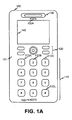
- Fig. 1A is a diagram of an exemplary implementation of a mobile terminal 100 consistent with the principles of the invention.
- Mobile terminal 100 may be a mobile communication device.
- a "mobile communication device” and/or “mobile terminal” may include a radiotelephone; a personal communications system (PCS) terminal that may combine a cellular radiotelephone with data processing, a facsimile, and data communications capabilities; a PDA that can include a radiotelephone, pager, Internet/intranet access, web browser, organizer, calendar, and/or global positioning system (GPS) receiver; and a laptop and/or palmtop receiver or other appliance that includes a radiotelephone transceiver.
- PCS personal communications system
- GPS global positioning system
- Terminal 100 may include housing 101, keypad 110, control keys 120, speaker 130, display 140, and microphones 150 and 150A.
- Housing 101 may include a structure configured to hold devices and components used in terminal 100.
- housing 10 may be formed from plastic, metal, or another material and may be configured to support keys 112A-L (collectively keys 112), control keys 120, speaker 130, display 140 and microphone 150 or 150A.
- housing 101 may form a front surface, or face of terminal 100.
- Keypad 110 may include devices, such as keys 112A-L, that can be used to enter information into terminal 100.
- Keys 112 may be used in a keypad (as shown in Fig. 1A ), in a keyboard, or in some other arrangement of keys. Implementations of keys 112 may have key information associated therewith, such as numbers, letters, symbols, etc.
- a user may interact with keys 112 to input key information into terminal 100. For example, a user may operate keys 112 to enter digits, commands, and/or text, into terminal 100.
- Control keys 120 may include buttons that permit a user to interact with terminal 100 to cause terminal 100 to perform an action, such as to take a digital photograph using a digital camera embedded in terminal 100, display a text message via display 140, raise or lower a volume setting for speaker 130, etc.
- Speaker 130 may include a device that provides audible information to a user of terminal 100. Speaker 130 may be located in an upper portion of terminal 100 and may function as an ear piece or with an ear piece when a user is engaged in a communication session using terminal 100.
- Display 140 may include a device that provides visual information to a user.
- display 140 may provide information regarding incoming or outgoing calls, text messages, games, images, video, phone books, the current date/time, volume settings, etc., to a user of terminal 100.
- display 140 may display still images or video images that are received via a lens.
- Microphones 150 and/or 150A may, respectively, include a device that converts speech or other acoustic signals into electrical signals for use by terminal 100.
- Microphone 150 may be located proximate to a lower side of terminal 100 and may convert spoken words or phrases into electrical signals for use by terminal 100.
- Microphone 150A may be located proximate to speaker 130 and may receive acoustic signals proximate to a user's ear while the user is engaged in a communications session using terminal 100. For example, microphone 150A may receive background noise and/or sound coming from speaker 130.
- Fig. 1B illustrates a back surface 102 of terminal 100.
- Back surface 102 may include a flash 160, a lens 170, a lens cover 180, and a range finder 190.
- Back surface 102 may be made of plastic, metal, and/or another material and may be configured to support flash 160, lens 170, lens cover 180, and range finder 190.
- Flash 160 may include a device to illuminate a subject that is being photographed with lens 170. Flash 160 may include light emitting diodes (LEDs) and/or other types of illumination devices.
- Lens 170 may include a device to receive optical information related to an image. For example, lens 170 may receive optical reflections from a subject and may capture a digital representation of the subject using the reflections. Lens 170 may include optical elements, mechanical elements, and/or electrical elements. An implementation of lens 170 may have an upper surface that faces a subject being photographed and a lower surface that faces an interior portion of terminal 100, such as a portion of terminal 100 housing electronic components.
- Lens cover 180 may include a device to protect and/or clean lens 170 when lens 170 is not in use.
- lens cover 180 may be slideably attached to back surface 102 so that lens cover 180 can be displaced over lens 170 (position 184 in Fig. 1B ) or displaced to uncover lens 170 (position 182 in Fig. 1B ).
- lens cover 180 may be pivotally mounted to back surface 102 (e.g., via hinges) in a manner whereby lens cover 180 can cover and/or uncover lens 170.
- lens cover 180 may be rotationally mounted to back surface 102 (e.g., via a pin-type connection).
- Lens cover 180 may be displaced via an actuator (e.g., an electrical and/or mechanical actuator) and/or manually (e.g., via an operator) to cover and/or uncover lens 170.
- actuator e.g., an electrical and/or mechanical actuator
- manually e.g., via an operator
- lens cover 180 may be fabricated from a substantially rigid material, such as plastic, metal, composite, etc.
- Range finder 190 may include a device to determine a range from lens 170 to a subject (e.g., a subject being photographed with terminal 100). Range finder 190 may be connected to an auto-focus element in lens 170 to bring a subject into focus with respect to lens 170. Range finder 190 may operate using ultrasonic signals, infrared signals, etc. consistent with the principles of the invention.
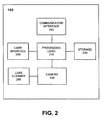
- Fig. 2 illustrates an exemplary functional diagram of mobile terminal 100 consistent with principles of the invention.
- terminal 100 may include processing logic 210, storage 220, a user interface 230, a communication interface 240, a camera 250 and a lens cleaner 260.
- Processing logic 210 may include a processor, microprocessor, an application specific integrated circuit (ASIC), field programmable gate array (FPGA), or the like.
- Processing logic 210 may include data structures or software programs to control operation of terminal 100 and its components, such as camera 250.
- Storage 220 may include a random access memory (RAM), a read only memory (ROM), a magnetic or optical disk and its corresponding drive and/or another type of memory to store data and instructions that may be used by processing logic 210.
- RAM random access memory
- ROM read only memory
- magnetic or optical disk and its corresponding drive and/or another type of memory to store data and instructions that may be used by processing logic 210.
- User interface 230 may include mechanisms for inputting information to terminal 100 and/or for outputting information from terminal 100.
- input and output mechanisms might include a speaker (e.g., speaker 130) to receive electrical signals and output audio signals, a microphone (e.g., microphone 150 or 150A) to receive audio signals and output electrical signals, buttons (e.g., control keys 120 and/or keys 112) to permit data and control commands to be input into terminal 100, a display (e.g., display 140) to output visual information, and/or a vibrator to cause terminal 100 to vibrate.
- a speaker e.g., speaker 130
- a microphone e.g., microphone 150 or 150A
- buttons e.g., control keys 120 and/or keys 112
- a display e.g., display 140
- a vibrator to cause terminal 100 to vibrate.
- Communication interface 240 may include, for example, an antenna, a transmitter that may convert baseband signals from processing logic 210 to radio frequency (RF) signals and/or a receiver that may convert RF signals from the antenna to baseband signals.
- communication interface 240 may include a transceiver that performs the functions of both a transmitter and a receiver.
- Camera 250 may include hardware and software based logic to create still or moving images using terminal 100.
- camera 250 may include solid-state image capturing components, such as charge coupled devices (CCDs).
- CCDs charge coupled devices
- camera may include non-solid state devices, such as devices used to record images onto film.
- Implementations of camera 250 may operate with an object detection device that determines when foreign objects are on an upper surface of lens 170.
- the object detection device may use image processing techniques, such as evaluating light reflections with respect to lens 170, light transmittance through lens 170, and/or shadows on a surface of lens 170, to determine when foreign objects are located on a surface of lens 170.
- Camera 250 may communicate an object detection result to lens cleaner 260.
- Lens cleaner 260 may include devices to remove foreign objects, such as dirt and/or debris, from a surface of lens 170.
- lens cleaner 260 may be integrated into lens cover 180.
- Lens cleaner 260 may use mechanical, pneumatic, fluid-based, and/or electrical cleaning techniques to remove dirt and/or debris from a surface of lens 170.
- Implementations of lens cleaner 260 may receive an instruction, such as an instruction related to a result determined by an object detection device, and may clean a surface of lens 170 in response to the instruction.
- Implementations of lens cleaner 260 may be implemented to clean a surface of lens 170 whenever a lens cleaning device passes over lens 170 and/or to clean a surface of lens 170 only when a foreign object is present thereon.
- terminal 100 may perform certain operations relating to removing objects (e.g., dust) from a surface of lens 170.
- Terminal 100 may perform these operations in response to processing logic 210 executing software instructions of a lens cover/lens cleaner displacement application contained in a computer-readable medium, such as storage 220.
- a computer-readable medium may be defined as a physical or logical memory device and/or carrier wave.
- the software instructions may be read into storage 220 from another computer-readable medium or from another device via communication interface 240.
- the software instructions contained in storage 220 may cause processing logic 210 to perform processes that will be described later.
- processing logic 210 may cause processing logic 210 to perform processes that will be described later.
- hardwired circuitry may be used in place of or in combination with software instructions to implement processes consistent with principles of the invention.
- implementations consistent with principles of the invention are not limited to any specific combination of hardware circuitry and software.
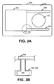
- Fig. 3A illustrates an exemplary implementation of a mobile terminal that includes a lens cover consistent with principles of the invention.
- terminal 300 may include lens 170, back surface 302, upper guide 320, lower guide 330, and lens cover 380.
- Lens 170 may operate as described in connection with Fig. 1B .
- Back surface 302 may operate as a host surface and may support lens 170, upper guide 320, lower guide 330, and lens cover 380.
- Guides 320 and 330 may include channels recessed into back surface 302 that allow one or more support members 340 ( Fig. 3B ) to slide from a first position that leaves lens 170 uncovered to a second position that leaves lens 170 covered.
- Lens cover 380 may be configured in a manner similar to lens cover 180.
- Lens cover 380 may operate as a receiving device to receive a lens cleaning device.
- lens cover 380 may be configured to removeably support a lens cleaning device on a lower surface thereof (i.e., a surface that faces an upper surface of lens 170).
- the lens cleaning device may be arranged to contact a surface of lens 170 when lens cover 380 is in a certain position (e.g., a closed position where lens cover 380 is covering lens 170).
- Fig. 3B illustrates a diagram of an exemplary guide 320 or 330 used in the implementation of Fig. 3A .
- Guide 320/330 may be recessed into back surface 302 and may receive supporting member 340.
- Supporting member 340 may be shaped to engage guide 320/330 in a manner that allows supporting member 340 to slide along guide 320/330 without becoming disengaged from guide 320/330.
- Supporting member 340 may be configured so that a lower end of supporting member 340 engages guide 320/330 and an upper end of supporting member 340 engages a surface of lens cover 380, such as a lower surface of lens cover 380.
- Fig. 4 illustrates an exemplary implementation of lens cover 380 that includes a lens cleaner consistent with principles of the invention.
- the implementation of Fig. 4 may include lens cover 380, supporting members 340, and lens cleaner 430.
- Lens cleaner 430 may include a device to remove foreign objects, such as dust, dirt, and/or debris, from an upper surface of lens 170.
- lens cleaner 430 may include a mechanical device such as a lens tissue, lens cloth, or lens brush that is removeably affixed to an inner surface of lens cover 380.
- a mechanical implementation of lens cleaner 430 may remove foreign objects from a surface of lens 170 using friction and/or adhesion.
- lens cleaner 430 may include a fluid and/or mechanical-based device, such as a fluid reservoir for depositing lens cleaning fluid onto an upper surface of lens 170 and a mechanical lens wiper (e.g., a compliant rubber wiper) to remove the fluid and/or foreign objects from a surface of lens 170.
- lens cleaner 430 may include electrical and/or pneumatic (e.g., gas-based) lens cleaning devices. Implementations of lens cleaner 430 may be configured to remove foreign objects from a surface of lens 170 when lens cleaner 430 and/or lens cover 380 are proximate to the surface of lens 170.
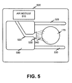
- Fig. 5 illustrates an exemplary diagram of a mobile terminal that includes a lens cover utilizing a nozzle consistent with principles of the invention.
- terminal 500 may include lens 170, upper guide 320, lower guide 330, air module 510, air duct 520, nozzle 530, air stream 540, and lens cover 580.
- Lens 170, upper guide 320, and lower guide 330 may operate as previously described.
- Air module 510 may include a device to produce a positive or negative air pressure in air duct 520.
- air module 510 may include a diaphragm, pump, vacuum device, etc.
- Implementations of air module 510 may be electrically, electro-mechanically, and/or mechanically operated.
- Air duct 520 may include a structure to direct a volume of air from one location to another. Air duct 520 may act as an air guide and may be fabricated from plastic, composite, etc.
- Nozzle 530 may include a device to direct the air volume at a location as an air stream 540, such as an upper surface of lens 170. Nozzle 530 may be adapted to produce a determined air velocity on a surface of lens 170 to dislodge foreign objects from the surface of lens 170.
- Lens cover 580 may include a device to cover and/or uncover lens 170.
- Lens cover 580 may include air duct 520 and/or nozzle 530.
- air module 510 and lens cover 580 may operate so that air stream 540 is produced when lens cover 580 is moved toward lens 170.
- Lens cover 580 may operate to remove foreign objects from an upper surface of lens 170 before lens cover 580 covers lens 170.
- air duct 520 and nozzle 530 may be supported on a lower surface of lens cover 580 proximate to an upper surface of lens 170.
- air module 510 may supply a volume of air to nozzle 530.
- Nozzle 530 may direct the air volume at the upper surface of lens 170 at a determined velocity so as to remove foreign objects from the upper surface of lens 170.
- Fig. 6 illustrates an exemplary implementation of a mobile terminal that includes a lens cover utilizing an electrical lens cleaning technique consistent with principles of the invention.
- terminal 600 may include lens 170, upper guide 320, lower guide 330, electronic module 610, positive supply rail 620, negative supply rail 630, cross-wire 640, and lens cover 680.
- the implementation of Fig. 6 may be adapted to create a potential, such as a static potential, on a lower surface of lens cover 680 proximate to an upper surface of lens 170.
- the potential may cause foreign objects to transfer from the upper surface of lens 170 to the lower surface of lens cover 680, thereby removing the foreign objects from a surface of lens 170.
- Electronic module 610 may include a device to supply a voltage and/or current to positive supply rail 620 and/or negative supply rail 630.
- Electronic module 610 may be powered via a battery and may supply a potential to positive and negative supply rails 620/630 when lens cover 680 is displaced toward lens 170 and/or when lens cover 680 is positioned over lens 170.
- Positive supply rail 620 and negative supply rail 630 may include devices or structures to conduct a voltage or current to cross-wires 640. Implementations of positive supply rail 620 and negative supply rail 630 may be fabricated from electrically conductive material, such as metal, and/or materials that build up electrical potentials when power is applied thereto via electronic module 610.
- Cross-wire 640 may include a device or structure to conduct an electrical signal. Implementations of cross-wire 640 may be made of metal and/or other materials that pass an electrical signal and/or that respond to an electrical signal. For example, implementations of cross-wires 640 may include materials that build up electrical potentials in response to electrical signals.
- Lens cover 680 may include a structure to support positive supply rail 620, negative supply rail 630 and/or one or more cross-wires 640 proximate to an upper surface of lens 170. Lens cover 680 may be slideably, pivotally, rotationally, and/or removeably supported on a surface of terminal 600.
- Fig. 7 illustrates an exemplary process that can be used to clean lens 170 consistent with principles of the invention.
- the exemplary process may begin with the detection of one or more foreign objects on lens 170 (block 710). Implementations may detect foreign objects on lens 170 automatically (e.g., via an object detection device) and/or manually (e.g., via an operator of terminal 100). Implementations may clean a surface of lens 170 when objects are detected thereon or whenever lens cover 180, 380, 580, 680 (collectively "the lens cover") is positioned over a surface of lens 170, Block 710 may be omitted in implementations that do not detect the presence of a foreign object on a surface of lens 170.
- the lens cover may be used to cover lens 170 (block 720).
- the lens cover may be slideably or pivotally supported on a surface of terminal 100, 300, 500, 600 (collectively "the terminal").
- the lens cover may be slid from a first position that leaves an upper surface of lens 170 exposed (e.g., to take a photograph) into a second position that covers lens 170 (e.g., to protect lens 170 when not in use).
- the lens cover may remove foreign objects when foreign objects are detected on a surface of lens 170 and/or when foreign objects are on a surface of lens 170 whether or not the foreign objects have been detected.
- lens cover 380 may be configured with a lens cleaner 430 that includes one or more layers of lens tissue and/or lens cloth.
- Lens cover 380 may be adapted to remove foreign objects from an upper surface of lens 170 whenever lens cover 380 moves over the upper surface of lens 170.
- Lens cleaner 430 may physically contact an upper surface of lens 170 and may cause foreign objects to become attached to or embedded in lens cleaner 430 when lens cleaner 430 is moved across the upper surface of lens 170.
- Implementations of lens cleaner 430 may operate dry and/or moistened (e.g., with a lens cleaning solution).
- Lens cover 580 or 680 may operate with a foreign object detection device and may remove foreign objects from an upper surface of lens 170 when the presence of one or more foreign objects is detected by the foreign object detection device.
- air module 510 may receive an instruction to deliver a volume of air to air duct 520 and nozzle 530 when a foreign object is detected on an upper surface of lens 170.
- Lens cover 580 may be moved toward lens 170 and air stream 540 may be expelled via nozzle 530 at a determined velocity, where the determined velocity is adapted to remove foreign objects from the upper surface of lens 170.
- Foreign objects may be dislodged from the upper surface of lens 170 via air stream 540.
- Lens cover 680 may be adapted to apply a potential to positive supply rail 620 and negative supply rail 630 when a foreign object is detected on an upper surface of lens 170.
- electronic module 610 may receive an instruction from a foreign object detection device that a foreign object is on the upper surface of lens 170.
- Electronic module 610 may apply a potential to positive supply rail 620 and negative supply rail 630 when lens cover 680 is moved toward lens 170 and/or when lens cover 680 is positioned over lens 170.
- the applied potential may be adapted to produce a charge across one or more cross-wires 640.
- the charge may be adapted to attract foreign objects that are on the upper surface of lens 170 to the one or more cross-wires 640.
- lens 170 may be uncovered (block 730).
- lens cover 380 may be moved away from lens 170 so that lens 170 is exposed and may be used to capture an image.
- Lens cover 580 and/or 680 may likewise be moved away from lens 170 thereby exposing lens 170 for use in capturing images.
- Foreign objects may be removed from the lens cover as needed (block 740).
- lens cover 380 may need to be cleaned whenever lens cleaner 430 passes over lens 170.
- lens cover 380 may be cleaned periodically, such as when lens cleaner 380 has reached a capacity limit with respect to foreign objects removed from lens 170.
- Implementations of lens cover 380 may be removed from terminal 300 to expose an under side (e.g., lower surface) of lens cover 380 that supports lens cleaner 430.
- a user of terminal 300 may remove a top layer of lens cleaner 430 (e.g., by removing the topmost layer of lens tissue or lens cloth) to remove foreign object attached thereto and to expose a clean layer (e.g., a layer immediately below the removed layer) for use in subsequently removing foreign objects from an upper surface of lens 170.
- the user may clean the topmost layer of lens cleaner 430 (e.g., by rinsing or vacuuming lens cleaner 430) to remove foreign objects attached thereto.
- Electronic module 610 may be adapted to apply a reverse potential, as compared to the potential used to attract foreign objects to cross-wires 640, when lens cover 680 is not covering lens 170.
- the reversed potential may cause foreign objects to be displaced away from cross-wires 640 thereby cleaning cross-wires 640 and/or lens cover 680.
- the clean cross-wires 640 may be used to remove foreign objects from an upper surface of lens 170 at a later time.
- Implementations consistent with principles of the invention may facilitate removing foreign objects from surfaces, such as a surface of a lens.
- Implementations may employ mechanical, electrical, pneumatic, and/or fluid-based techniques to remove foreign objects from a surface.
- Other implementations may employ a combination of techniques to remove foreign objects consistent with principles of the invention.
- logic may include hardware, such as hardwired logic, an application specific integrated circuit, a field programmable gate array, a microprocessor, software, or a combination of hardware and software.
Landscapes
- Physics & Mathematics (AREA)
- General Physics & Mathematics (AREA)
- Optics & Photonics (AREA)
- Engineering & Computer Science (AREA)
- Multimedia (AREA)
- Signal Processing (AREA)
- Camera Bodies And Camera Details Or Accessories (AREA)
- Studio Devices (AREA)
- Blocking Light For Cameras (AREA)
- Accessories Of Cameras (AREA)
- Eyeglasses (AREA)
Claims (12)
- Linsenabdeckung (180, 380), die entfernbar an einem mobilen Endgerät angebracht werden kann, wobei das mobile Endgerät eine Host-Oberfläche und eine Linse umfasst, und wobei die Linsenabdeckung (180, 380) umfasst:einen Linsenreiniger (260, 430), ausgelegt zum Reinigen einer Oberfläche der Linse, wenn der Linsenreiniger (260, 430) sich in einer ersten Position in der Nähe der Oberfläche der Linse befindet, wobei der Linsenreiniger ausgelegt ist zum Empfangen von Anweisungen von einer Objekt-Erfassungseinheit, die ausgelegt ist zum Erfassen, ob sich ein fremdes Objekt auf der Oberfläche der Linse befindet; undUnterstützungselemente (340), um die Linsenabdeckung (180) auf der Host-Oberfläche bewegbar zu unterstützen, so dass die Linsenabdeckung (180, 380) den Linsenreiniger (260, 430) an der ersten Position in der Nähe der Oberfläche der Linse beibehalten kann, wenn die Objekt-Erfassungseinheit das fremde Objekt auf der Oberfläche der Linse erfasst, und um den Linsenreiniger (260, 430) an einer zweiten Position von der Oberfläche der Linse entfernt beizubehalten, so dass die Linse eine optische Information in Bezug auf ein Subjekt empfangen kann, wenn die Objekt-Erfassungseinheit das fremde Objekt auf der Oberfläche der Linse nicht erfasst.
- Linsenabdeckung nach Anspruch 1, wobei der Linsenreiniger (260, 430) die Oberfläche der Linse kontaktiert, wenn sich der Linsenreiniger in der ersten Position befindet.
- Linsenabdeckung nach Anspruch 1, wobei der Linsenreiniger (260, 430) das fremde Objekt unter Verwendung einer elektrischen Ladung, eines Fluids, eines Gases oder Reibung entfernt.
- Linsenabdeckung nach Anspruch 1, wobei der Linsenreiniger (260, 430) ein oder mehrere Linsen-Stofftücher, Linsen-Reinigungstücher oder Linsenbürsten umfasst.
- Linsenabdeckung (180, 380) nach Anspruch 1, wobei die Linsenabdeckung (180, 380) mit dem Linsenreiniger (260, 430) von der ersten Position in die zweite Position geschoben wird, von der ersten Position in die zweite Position schwenkt, oder von der ersten Position in die zweite Position rotiert.
- Mobiles Endgerät (100), mit:einer Linse (170) zum:Empfangen optischer Informationen durch eine äußere Oberfläche der Linse;einer Objekt-Erfassungseinheit zum:Erfassen, ob ein fremdes Objekt auf der äußeren Oberfläche der Linse vorhanden ist;einem Linsenreiniger zum:Entfernen des fremden Objekts von der äußeren Oberfläche, wenn der Linsenreiniger in der Nähe der äußeren Oberfläche ist; undeiner Linsenabdeckung (180) mit einer inneren Oberfläche, wobei die Linsenabdeckung ausgelegt ist zum:Unterstützen des Linsenreinigers auf der inneren Oberfläche, so dass der Linsenreiniger an der äußeren Oberfläche verfügbar ist, undBewegen von einer ersten Position in eine zweite Position, wodurch der Linsenreiniger in die Nähe der äußeren Oberfläche gebracht wird, um das fremde Objekt von der äußeren Oberfläche zu entfernen, wenn die Objekt-Erfassungseinheit das fremde Objekt auf der äußeren Oberfläche der Linse erfasst.
- Mobiles Endgerät nach Anspruch 6, ferner mit:einem Aktuator zum Bewegen der Linsenabdeckung von der ersten Position in die zweite Position.
- Mobiles Endgerät nach Anspruch 6, wobei der Linsenreiniger umfasst:ein Stofftuch, ein Reinigungstuch, eine Düse, ein Fluid oder einen elektrischen Leiter.
- Mobiles Endgerät nach Anspruch 6, wobei die Linsenabdeckung auf dem mobilen Endgerät entfernbar unterstützt wird.
- Mobiles Endgerät nach Anspruch 6, wobei die Linsenabdeckung sich in Bezug auf eine Oberfläche des mobilen Endgeräts schwenkbar, lateral oder rotationsartig bewegt.
- Automatisiertes Verfahren zum Reinigen einer Linse eines mobilen Endgeräts, umfassend:Erfassen, mit einer Objekt-Erfassungseinheit, ob ein fremdes Objekt auf einer oberen Oberfläche der Linse vorhanden ist;Versetzen einer Linsenabdeckung von einer ersten Position in eine zweite Position in Bezug auf die obere Oberfläche der Linse, wenn das fremde Objekt auf der oberen Oberfläche erfasst wird;Entfernen des fremdem Objekts von der oberen Oberfläche durch einen Linsenreiniger, der auf der Linsenabdeckung unterstützt wird, wenn die Linsenabdeckung in der zweiten Position ist, wobei das fremde Objekt durch den auf der Linsenabdeckung unterstützen Linsenreiniger entfernt wird; undZurücksetzen der Linsenabdeckung in die erste Position, so dass eine optische Information die Linse erreichen kann.
- Verfahren nach Anspruch 11, ferner umfassend
Empfangen eines Eingabesignals von einer Steuertaste oder einer Tastaturtaste; und
Aufnehmen eines Bildes, als Antwort auf das Eingabesignal, unter Verwendung der Linse.
Applications Claiming Priority (2)
| Application Number | Priority Date | Filing Date | Title |
|---|---|---|---|
| US11/433,572 US7810511B2 (en) | 2006-05-15 | 2006-05-15 | Lens cleaner |
| PCT/IB2006/054260 WO2007132299A1 (en) | 2006-05-15 | 2006-11-14 | Lens cleaner |
Publications (2)
| Publication Number | Publication Date |
|---|---|
| EP2018588A1 EP2018588A1 (de) | 2009-01-28 |
| EP2018588B1 true EP2018588B1 (de) | 2011-06-08 |
Family
ID=37945003
Family Applications (1)
| Application Number | Title | Priority Date | Filing Date |
|---|---|---|---|
| EP06821448A Not-in-force EP2018588B1 (de) | 2006-05-15 | 2006-11-14 | Linsenreiniger |
Country Status (7)
| Country | Link |
|---|---|
| US (1) | US7810511B2 (de) |
| EP (1) | EP2018588B1 (de) |
| JP (1) | JP2009537855A (de) |
| CN (1) | CN101438200B (de) |
| AT (1) | ATE512384T1 (de) |
| BR (1) | BRPI0621651A2 (de) |
| WO (1) | WO2007132299A1 (de) |
Families Citing this family (55)
| Publication number | Priority date | Publication date | Assignee | Title |
|---|---|---|---|---|
| US8358928B2 (en) * | 2010-04-12 | 2013-01-22 | Aadyn Technology, Llc | Lens guard |
| WO2012129521A1 (en) * | 2011-03-23 | 2012-09-27 | Gentex Corporation | Lens cleaning apparatus |
| CN102364375B (zh) * | 2011-11-09 | 2013-09-25 | 广州视声电子科技有限公司 | 一种移动设备的镜头清洁装置 |
| US9436005B2 (en) | 2012-08-02 | 2016-09-06 | Gentex Corporation | Amplified piezoelectric camera lens cleaner |
| US9671595B2 (en) | 2013-01-05 | 2017-06-06 | Light Labs Inc. | Methods and apparatus for using multiple optical chains in paralell |
| US9253375B2 (en) * | 2013-04-02 | 2016-02-02 | Google Inc. | Camera obstruction detection |
| US9083864B2 (en) * | 2013-07-31 | 2015-07-14 | Ford Global Technologies, Llc | Self-cleaning camera lens |
| US9423588B2 (en) | 2013-10-18 | 2016-08-23 | The Lightco Inc. | Methods and apparatus for supporting zoom operations |
| US9374514B2 (en) | 2013-10-18 | 2016-06-21 | The Lightco Inc. | Methods and apparatus relating to a camera including multiple optical chains |
| US9197816B2 (en) | 2013-10-18 | 2015-11-24 | The Lightco Inc. | Zoom related methods and apparatus |
| US9467627B2 (en) | 2013-10-26 | 2016-10-11 | The Lightco Inc. | Methods and apparatus for use with multiple optical chains |
| US9736365B2 (en) | 2013-10-26 | 2017-08-15 | Light Labs Inc. | Zoom related methods and apparatus |
| US9426365B2 (en) | 2013-11-01 | 2016-08-23 | The Lightco Inc. | Image stabilization related methods and apparatus |
| US9554031B2 (en) | 2013-12-31 | 2017-01-24 | Light Labs Inc. | Camera focusing related methods and apparatus |
| EP3097755A4 (de) | 2014-01-21 | 2017-09-13 | Positec Power Tools (Suzhou) Co., Ltd | Automatischer rasenmäher |
| EP2899692B1 (de) * | 2014-01-28 | 2019-09-04 | Honda Research Institute Europe GmbH | Verfahren, System, Bildgebungsvorrichtung, bewegliche Vorrichtung und Programmprodukt zum Erfassen von statischen Elementen in Video- und Bildquellen |
| US9979878B2 (en) | 2014-02-21 | 2018-05-22 | Light Labs Inc. | Intuitive camera user interface methods and apparatus |
| US20150244949A1 (en) | 2014-02-21 | 2015-08-27 | Rajiv Laroia | Illumination methods and apparatus |
| WO2016004422A1 (en) * | 2014-07-04 | 2016-01-07 | The Lightco Inc. | Methods and apparatus relating to detection and/or indicating a dirty lens condition |
| US10110794B2 (en) | 2014-07-09 | 2018-10-23 | Light Labs Inc. | Camera device including multiple optical chains and related methods |
| CN104128343B (zh) * | 2014-07-23 | 2016-02-17 | 惠州市德赛自动化技术有限公司 | 一种光学镜头自动除尘设备 |
| US9912864B2 (en) | 2014-10-17 | 2018-03-06 | Light Labs Inc. | Methods and apparatus for using a camera device to support multiple modes of operation |
| EP3235243A4 (de) | 2014-12-17 | 2018-06-20 | Light Labs Inc. | Verfahren und vorrichtung zur implementierung und verwendung von kameravorrichtungen |
| US9544503B2 (en) | 2014-12-30 | 2017-01-10 | Light Labs Inc. | Exposure control methods and apparatus |
| US9824427B2 (en) | 2015-04-15 | 2017-11-21 | Light Labs Inc. | Methods and apparatus for generating a sharp image |
| US9967535B2 (en) | 2015-04-17 | 2018-05-08 | Light Labs Inc. | Methods and apparatus for reducing noise in images |
| US10075651B2 (en) | 2015-04-17 | 2018-09-11 | Light Labs Inc. | Methods and apparatus for capturing images using multiple camera modules in an efficient manner |
| US9857584B2 (en) | 2015-04-17 | 2018-01-02 | Light Labs Inc. | Camera device methods, apparatus and components |
| US10091447B2 (en) | 2015-04-17 | 2018-10-02 | Light Labs Inc. | Methods and apparatus for synchronizing readout of multiple image sensors |
| US9930233B2 (en) | 2015-04-22 | 2018-03-27 | Light Labs Inc. | Filter mounting methods and apparatus and related camera apparatus |
| US10129483B2 (en) | 2015-06-23 | 2018-11-13 | Light Labs Inc. | Methods and apparatus for implementing zoom using one or more moveable camera modules |
| US10491806B2 (en) | 2015-08-03 | 2019-11-26 | Light Labs Inc. | Camera device control related methods and apparatus |
| US10365480B2 (en) | 2015-08-27 | 2019-07-30 | Light Labs Inc. | Methods and apparatus for implementing and/or using camera devices with one or more light redirection devices |
| US9749549B2 (en) | 2015-10-06 | 2017-08-29 | Light Labs Inc. | Methods and apparatus for facilitating selective blurring of one or more image portions |
| US9602703B1 (en) | 2015-11-25 | 2017-03-21 | GM Global Technology Operations LLC | Camera system |
| US10003738B2 (en) | 2015-12-18 | 2018-06-19 | Light Labs Inc. | Methods and apparatus for detecting and/or indicating a blocked sensor or camera module |
| US10225445B2 (en) | 2015-12-18 | 2019-03-05 | Light Labs Inc. | Methods and apparatus for providing a camera lens or viewing point indicator |
| US10306218B2 (en) | 2016-03-22 | 2019-05-28 | Light Labs Inc. | Camera calibration apparatus and methods |
| US9880382B1 (en) * | 2016-04-14 | 2018-01-30 | Ford Global Technlogies, Llc | Exterior vehicle camera protection and cleaning mechanisms |
| WO2017192672A1 (en) * | 2016-05-03 | 2017-11-09 | Continental Automotive Systems, Inc. | Cleaning device for an imaging sensor |
| US9948832B2 (en) | 2016-06-22 | 2018-04-17 | Light Labs Inc. | Methods and apparatus for synchronized image capture in a device including optical chains with different orientations |
| US12370579B2 (en) | 2017-12-18 | 2025-07-29 | Illinois Tool Works Inc. | Self cleaning apparatus and method |
| US10983335B2 (en) * | 2017-12-18 | 2021-04-20 | Illinois Tool Works Inc. | Self cleaning photo eye apparatus and method |
| CN108111736A (zh) * | 2018-04-16 | 2018-06-01 | 南京点耐特信息科技有限公司 | 一种可以自我清洁的摄像头 |
| CN111031199A (zh) * | 2018-10-09 | 2020-04-17 | 致伸科技股份有限公司 | 摄像模块 |
| US10908002B2 (en) * | 2018-11-14 | 2021-02-02 | Ford Global Technologies, Llc | Sensor airflow apparatus |
| JP7267728B2 (ja) * | 2018-12-19 | 2023-05-02 | ニデックプレシジョン株式会社 | 羽根駆動装置及び電子機器 |
| JP2020098294A (ja) * | 2018-12-19 | 2020-06-25 | 日本電産コパル株式会社 | 羽根駆動装置及び電子機器 |
| US10761190B1 (en) * | 2019-04-12 | 2020-09-01 | Ford Global Technologies, Llc | Moisture control for sensor assembly |
| CN112044862A (zh) * | 2019-06-06 | 2020-12-08 | 中信戴卡股份有限公司 | 镜头保护装置及镜头保护方法 |
| CN115066653A (zh) | 2020-02-17 | 2022-09-16 | 松下知识产权经营株式会社 | 用于电子设备的相机的作为隐私保护遮板的遮蔽机构 |
| US20210341731A1 (en) * | 2020-04-30 | 2021-11-04 | Texas Instruments Incorporated | Utlrasonic lens cleaner |
| CN112672013B (zh) * | 2020-12-21 | 2022-06-10 | 中南信息科技(深圳)有限公司 | 一种安防监控高清摄像头 |
| CN113814212B (zh) * | 2021-09-06 | 2022-09-02 | 中南大学 | 一种基于镜片模糊检测的前置镜片在线智能自清洗装置及其方法 |
| US12509026B2 (en) * | 2022-07-29 | 2025-12-30 | Gm Cruise Holdings Llc | System and method for cleaning sensors of autonomous vehicles |
Family Cites Families (15)
| Publication number | Priority date | Publication date | Assignee | Title |
|---|---|---|---|---|
| US2583228A (en) | 1946-07-08 | 1952-01-22 | Numbers William | Combined lens cover and lens brush |
| JPH02310548A (ja) | 1989-05-26 | 1990-12-26 | Mitsubishi Electric Corp | レンズキャップ |
| JP3159738B2 (ja) * | 1991-07-30 | 2001-04-23 | 旭光学工業株式会社 | 光学機器のレンズキャップ |
| US5406413A (en) | 1991-07-30 | 1995-04-11 | Asahi Kogaku Kogyo Kabushiki Kaisha | Lens cover apparatus of optical instrument |
| JPH05151601A (ja) | 1991-11-29 | 1993-06-18 | Fujitsu General Ltd | レンズクリーニング装置 |
| JPH05274706A (ja) * | 1992-03-28 | 1993-10-22 | Kyocera Corp | 光記録再生装置 |
| JPH09282694A (ja) * | 1996-04-17 | 1997-10-31 | Canon Inc | 光記録再生装置 |
| JP2000078357A (ja) * | 1998-08-26 | 2000-03-14 | Ricoh Co Ltd | 画像読取装置 |
| JP2002310548A (ja) * | 2001-04-16 | 2002-10-23 | Matsushita Refrig Co Ltd | 給水装置 |
| CN1235085C (zh) * | 2002-01-14 | 2006-01-04 | 明基电通股份有限公司 | 镜头盖组件 |
| US6793416B2 (en) * | 2002-03-15 | 2004-09-21 | Professional Sounds, Inc. | System and method for protecting and clearing the lens of an optical surveillance device operating in a hostile environment |
| JP4107880B2 (ja) * | 2002-05-24 | 2008-06-25 | 三洋電機株式会社 | 光透過面の埃除去機能を具えた光学機器 |
| US7138640B1 (en) * | 2002-10-17 | 2006-11-21 | Kla-Tencor Technologies, Corporation | Method and apparatus for protecting surfaces of optical components |
| JP2004260615A (ja) * | 2003-02-26 | 2004-09-16 | Canon Inc | 撮像装置 |
| JP2005173191A (ja) | 2003-12-11 | 2005-06-30 | Olympus Corp | 光路折り曲げ光学系 |
-
2006
- 2006-05-15 US US11/433,572 patent/US7810511B2/en not_active Expired - Fee Related
- 2006-11-14 CN CN2006800545933A patent/CN101438200B/zh not_active Expired - Fee Related
- 2006-11-14 JP JP2009510562A patent/JP2009537855A/ja active Pending
- 2006-11-14 AT AT06821448T patent/ATE512384T1/de not_active IP Right Cessation
- 2006-11-14 BR BRPI0621651-0A patent/BRPI0621651A2/pt not_active IP Right Cessation
- 2006-11-14 WO PCT/IB2006/054260 patent/WO2007132299A1/en not_active Ceased
- 2006-11-14 EP EP06821448A patent/EP2018588B1/de not_active Not-in-force
Also Published As
| Publication number | Publication date |
|---|---|
| WO2007132299A1 (en) | 2007-11-22 |
| US20070261711A1 (en) | 2007-11-15 |
| CN101438200A (zh) | 2009-05-20 |
| ATE512384T1 (de) | 2011-06-15 |
| BRPI0621651A2 (pt) | 2012-10-09 |
| JP2009537855A (ja) | 2009-10-29 |
| US7810511B2 (en) | 2010-10-12 |
| CN101438200B (zh) | 2011-04-20 |
| EP2018588A1 (de) | 2009-01-28 |
Similar Documents
| Publication | Publication Date | Title |
|---|---|---|
| EP2018588B1 (de) | Linsenreiniger | |
| JP5247384B2 (ja) | 撮像装置、情報処理方法、プログラムおよび記憶媒体 | |
| JP2024012667A (ja) | 電気掃除装置及び電気掃除装置用プログラム | |
| US20050275738A1 (en) | Digital camera and cleaning apparatus therefor | |
| KR102219801B1 (ko) | 인공지능을 이용한 이동 로봇 및 이동 로봇의 제어방법 | |
| JP2010232755A (ja) | ハンズフリー通話装置、指向性調整方法、指向性調整プログラム | |
| WO2004080039A1 (ja) | 携帯端末 | |
| CN106725127A (zh) | 扫地机器人的清扫方法及装置 | |
| US20120287303A1 (en) | Sound separating device and camera unit including the same | |
| US20050129394A1 (en) | Cleaning apparatus for camera | |
| CN105559696A (zh) | 设备控制方法、系统及终端 | |
| US7385150B1 (en) | Sliding mechanism for device with two keyboards | |
| CN103002214A (zh) | 摄影装置以及摄影方法 | |
| US20070292118A1 (en) | Underwater image capture | |
| JP4349947B2 (ja) | レンズ装置及びカメラモジュール | |
| JP2006100875A (ja) | デジタルカメラの清掃方法及び清掃システム | |
| JP3847158B2 (ja) | 携帯電話装置 | |
| JP2005181541A (ja) | 撮像装置 | |
| CN111527446A (zh) | 摄像设备及其控制方法和记录介质 | |
| KR20090105366A (ko) | 촬상 장치용 청소 장치 | |
| JP2005260674A (ja) | 携帯情報端末機 | |
| JP2008145929A (ja) | レンズユニット、撮像装置、及びレンズユニットの製造方法 | |
| JP2007047487A (ja) | デジタルカメラのための塵埃除去装置 | |
| US20080007402A1 (en) | Portable monitoring assembly | |
| JP2013055765A (ja) | 超音波モータユニット、レンズ鏡筒及び撮影機器 |
Legal Events
| Date | Code | Title | Description |
|---|---|---|---|
| PUAI | Public reference made under article 153(3) epc to a published international application that has entered the european phase |
Free format text: ORIGINAL CODE: 0009012 |
|
| 17P | Request for examination filed |
Effective date: 20081103 |
|
| AK | Designated contracting states |
Kind code of ref document: A1 Designated state(s): AT BE BG CH CY CZ DE DK EE ES FI FR GB GR HU IE IS IT LI LT LU LV MC NL PL PT RO SE SI SK TR |
|
| AX | Request for extension of the european patent |
Extension state: AL BA HR MK RS |
|
| RIN1 | Information on inventor provided before grant (corrected) |
Inventor name: PALMQVIST, SVEN RUNE FREDRIK Inventor name: FAGRENIUS, NILS GUSTAV Inventor name: WALDT, CARL MAGNUS Inventor name: HAKANSSON, STEN OLA Inventor name: WEDEL, JOHAN MARTIN Inventor name: RALIN, EVA TINA |
|
| 17Q | First examination report despatched |
Effective date: 20100630 |
|
| GRAP | Despatch of communication of intention to grant a patent |
Free format text: ORIGINAL CODE: EPIDOSNIGR1 |
|
| DAX | Request for extension of the european patent (deleted) | ||
| RIN1 | Information on inventor provided before grant (corrected) |
Inventor name: HAKANSSON, STEN OLA Inventor name: RALIN, EVA TINA Inventor name: WALDT, CARL MAGNUS Inventor name: WEDEL, JOHAN MARTIN Inventor name: PALMQVIST, SVEN RUNE FREDRIK Inventor name: FAGRENIUS, NILS GUSTAV |
|
| GRAS | Grant fee paid |
Free format text: ORIGINAL CODE: EPIDOSNIGR3 |
|
| GRAA | (expected) grant |
Free format text: ORIGINAL CODE: 0009210 |
|
| AK | Designated contracting states |
Kind code of ref document: B1 Designated state(s): AT BE BG CH CY CZ DE DK EE ES FI FR GB GR HU IE IS IT LI LT LU LV MC NL PL PT RO SE SI SK TR |
|
| REG | Reference to a national code |
Ref country code: GB Ref legal event code: FG4D |
|
| REG | Reference to a national code |
Ref country code: CH Ref legal event code: EP |
|
| REG | Reference to a national code |
Ref country code: IE Ref legal event code: FG4D |
|
| REG | Reference to a national code |
Ref country code: DE Ref legal event code: R096 Ref document number: 602006022456 Country of ref document: DE Effective date: 20110721 |
|
| REG | Reference to a national code |
Ref country code: NL Ref legal event code: VDEP Effective date: 20110608 |
|
| PG25 | Lapsed in a contracting state [announced via postgrant information from national office to epo] |
Ref country code: LT Free format text: LAPSE BECAUSE OF FAILURE TO SUBMIT A TRANSLATION OF THE DESCRIPTION OR TO PAY THE FEE WITHIN THE PRESCRIBED TIME-LIMIT Effective date: 20110608 Ref country code: SE Free format text: LAPSE BECAUSE OF FAILURE TO SUBMIT A TRANSLATION OF THE DESCRIPTION OR TO PAY THE FEE WITHIN THE PRESCRIBED TIME-LIMIT Effective date: 20110608 |
|
| PG25 | Lapsed in a contracting state [announced via postgrant information from national office to epo] |
Ref country code: GR Free format text: LAPSE BECAUSE OF FAILURE TO SUBMIT A TRANSLATION OF THE DESCRIPTION OR TO PAY THE FEE WITHIN THE PRESCRIBED TIME-LIMIT Effective date: 20110909 Ref country code: ES Free format text: LAPSE BECAUSE OF FAILURE TO SUBMIT A TRANSLATION OF THE DESCRIPTION OR TO PAY THE FEE WITHIN THE PRESCRIBED TIME-LIMIT Effective date: 20110919 Ref country code: SI Free format text: LAPSE BECAUSE OF FAILURE TO SUBMIT A TRANSLATION OF THE DESCRIPTION OR TO PAY THE FEE WITHIN THE PRESCRIBED TIME-LIMIT Effective date: 20110608 Ref country code: CY Free format text: LAPSE BECAUSE OF FAILURE TO SUBMIT A TRANSLATION OF THE DESCRIPTION OR TO PAY THE FEE WITHIN THE PRESCRIBED TIME-LIMIT Effective date: 20110608 Ref country code: FI Free format text: LAPSE BECAUSE OF FAILURE TO SUBMIT A TRANSLATION OF THE DESCRIPTION OR TO PAY THE FEE WITHIN THE PRESCRIBED TIME-LIMIT Effective date: 20110608 Ref country code: LV Free format text: LAPSE BECAUSE OF FAILURE TO SUBMIT A TRANSLATION OF THE DESCRIPTION OR TO PAY THE FEE WITHIN THE PRESCRIBED TIME-LIMIT Effective date: 20110608 Ref country code: AT Free format text: LAPSE BECAUSE OF FAILURE TO SUBMIT A TRANSLATION OF THE DESCRIPTION OR TO PAY THE FEE WITHIN THE PRESCRIBED TIME-LIMIT Effective date: 20110608 |
|
| PG25 | Lapsed in a contracting state [announced via postgrant information from national office to epo] |
Ref country code: BE Free format text: LAPSE BECAUSE OF FAILURE TO SUBMIT A TRANSLATION OF THE DESCRIPTION OR TO PAY THE FEE WITHIN THE PRESCRIBED TIME-LIMIT Effective date: 20110608 Ref country code: NL Free format text: LAPSE BECAUSE OF FAILURE TO SUBMIT A TRANSLATION OF THE DESCRIPTION OR TO PAY THE FEE WITHIN THE PRESCRIBED TIME-LIMIT Effective date: 20110608 |
|
| PG25 | Lapsed in a contracting state [announced via postgrant information from national office to epo] |
Ref country code: CZ Free format text: LAPSE BECAUSE OF FAILURE TO SUBMIT A TRANSLATION OF THE DESCRIPTION OR TO PAY THE FEE WITHIN THE PRESCRIBED TIME-LIMIT Effective date: 20110608 Ref country code: PT Free format text: LAPSE BECAUSE OF FAILURE TO SUBMIT A TRANSLATION OF THE DESCRIPTION OR TO PAY THE FEE WITHIN THE PRESCRIBED TIME-LIMIT Effective date: 20111010 Ref country code: IS Free format text: LAPSE BECAUSE OF FAILURE TO SUBMIT A TRANSLATION OF THE DESCRIPTION OR TO PAY THE FEE WITHIN THE PRESCRIBED TIME-LIMIT Effective date: 20111008 Ref country code: EE Free format text: LAPSE BECAUSE OF FAILURE TO SUBMIT A TRANSLATION OF THE DESCRIPTION OR TO PAY THE FEE WITHIN THE PRESCRIBED TIME-LIMIT Effective date: 20110608 |
|
| PG25 | Lapsed in a contracting state [announced via postgrant information from national office to epo] |
Ref country code: SK Free format text: LAPSE BECAUSE OF FAILURE TO SUBMIT A TRANSLATION OF THE DESCRIPTION OR TO PAY THE FEE WITHIN THE PRESCRIBED TIME-LIMIT Effective date: 20110608 Ref country code: RO Free format text: LAPSE BECAUSE OF FAILURE TO SUBMIT A TRANSLATION OF THE DESCRIPTION OR TO PAY THE FEE WITHIN THE PRESCRIBED TIME-LIMIT Effective date: 20110608 Ref country code: PL Free format text: LAPSE BECAUSE OF FAILURE TO SUBMIT A TRANSLATION OF THE DESCRIPTION OR TO PAY THE FEE WITHIN THE PRESCRIBED TIME-LIMIT Effective date: 20110608 |
|
| PLBE | No opposition filed within time limit |
Free format text: ORIGINAL CODE: 0009261 |
|
| STAA | Information on the status of an ep patent application or granted ep patent |
Free format text: STATUS: NO OPPOSITION FILED WITHIN TIME LIMIT |
|
| 26N | No opposition filed |
Effective date: 20120309 |
|
| PG25 | Lapsed in a contracting state [announced via postgrant information from national office to epo] |
Ref country code: IT Free format text: LAPSE BECAUSE OF FAILURE TO SUBMIT A TRANSLATION OF THE DESCRIPTION OR TO PAY THE FEE WITHIN THE PRESCRIBED TIME-LIMIT Effective date: 20110608 |
|
| PG25 | Lapsed in a contracting state [announced via postgrant information from national office to epo] |
Ref country code: DK Free format text: LAPSE BECAUSE OF FAILURE TO SUBMIT A TRANSLATION OF THE DESCRIPTION OR TO PAY THE FEE WITHIN THE PRESCRIBED TIME-LIMIT Effective date: 20110608 Ref country code: MC Free format text: LAPSE BECAUSE OF NON-PAYMENT OF DUE FEES Effective date: 20111130 |
|
| REG | Reference to a national code |
Ref country code: CH Ref legal event code: PL |
|
| REG | Reference to a national code |
Ref country code: DE Ref legal event code: R097 Ref document number: 602006022456 Country of ref document: DE Effective date: 20120309 |
|
| PG25 | Lapsed in a contracting state [announced via postgrant information from national office to epo] |
Ref country code: CH Free format text: LAPSE BECAUSE OF NON-PAYMENT OF DUE FEES Effective date: 20111130 Ref country code: LI Free format text: LAPSE BECAUSE OF NON-PAYMENT OF DUE FEES Effective date: 20111130 |
|
| REG | Reference to a national code |
Ref country code: IE Ref legal event code: MM4A |
|
| PG25 | Lapsed in a contracting state [announced via postgrant information from national office to epo] |
Ref country code: IE Free format text: LAPSE BECAUSE OF NON-PAYMENT OF DUE FEES Effective date: 20111114 |
|
| PG25 | Lapsed in a contracting state [announced via postgrant information from national office to epo] |
Ref country code: LU Free format text: LAPSE BECAUSE OF NON-PAYMENT OF DUE FEES Effective date: 20111114 |
|
| PG25 | Lapsed in a contracting state [announced via postgrant information from national office to epo] |
Ref country code: BG Free format text: LAPSE BECAUSE OF FAILURE TO SUBMIT A TRANSLATION OF THE DESCRIPTION OR TO PAY THE FEE WITHIN THE PRESCRIBED TIME-LIMIT Effective date: 20110908 |
|
| PG25 | Lapsed in a contracting state [announced via postgrant information from national office to epo] |
Ref country code: TR Free format text: LAPSE BECAUSE OF FAILURE TO SUBMIT A TRANSLATION OF THE DESCRIPTION OR TO PAY THE FEE WITHIN THE PRESCRIBED TIME-LIMIT Effective date: 20110608 |
|
| PG25 | Lapsed in a contracting state [announced via postgrant information from national office to epo] |
Ref country code: HU Free format text: LAPSE BECAUSE OF FAILURE TO SUBMIT A TRANSLATION OF THE DESCRIPTION OR TO PAY THE FEE WITHIN THE PRESCRIBED TIME-LIMIT Effective date: 20110608 |
|
| PGFP | Annual fee paid to national office [announced via postgrant information from national office to epo] |
Ref country code: GB Payment date: 20141112 Year of fee payment: 9 Ref country code: DE Payment date: 20141111 Year of fee payment: 9 Ref country code: FR Payment date: 20141110 Year of fee payment: 9 |
|
| REG | Reference to a national code |
Ref country code: DE Ref legal event code: R119 Ref document number: 602006022456 Country of ref document: DE |
|
| GBPC | Gb: european patent ceased through non-payment of renewal fee |
Effective date: 20151114 |
|
| REG | Reference to a national code |
Ref country code: FR Ref legal event code: ST Effective date: 20160729 |
|
| PG25 | Lapsed in a contracting state [announced via postgrant information from national office to epo] |
Ref country code: DE Free format text: LAPSE BECAUSE OF NON-PAYMENT OF DUE FEES Effective date: 20160601 Ref country code: GB Free format text: LAPSE BECAUSE OF NON-PAYMENT OF DUE FEES Effective date: 20151114 |
|
| PG25 | Lapsed in a contracting state [announced via postgrant information from national office to epo] |
Ref country code: FR Free format text: LAPSE BECAUSE OF NON-PAYMENT OF DUE FEES Effective date: 20151130 |