EP2017516B1 - Raccord de tuyauterie et agencement de composant doté d'un raccord de tuyauterie - Google Patents
Raccord de tuyauterie et agencement de composant doté d'un raccord de tuyauterie Download PDFInfo
- Publication number
- EP2017516B1 EP2017516B1 EP08159509A EP08159509A EP2017516B1 EP 2017516 B1 EP2017516 B1 EP 2017516B1 EP 08159509 A EP08159509 A EP 08159509A EP 08159509 A EP08159509 A EP 08159509A EP 2017516 B1 EP2017516 B1 EP 2017516B1
- Authority
- EP
- European Patent Office
- Prior art keywords
- ring
- axially
- collar
- centring ring
- pipe
- Prior art date
- Legal status (The legal status is an assumption and is not a legal conclusion. Google has not performed a legal analysis and makes no representation as to the accuracy of the status listed.)
- Not-in-force
Links
- 238000007789 sealing Methods 0.000 claims description 15
- 238000005096 rolling process Methods 0.000 claims description 2
- 230000001747 exhibiting effect Effects 0.000 abstract 1
- 239000002245 particle Substances 0.000 description 4
- 238000009434 installation Methods 0.000 description 3
- 238000004519 manufacturing process Methods 0.000 description 3
- 238000002485 combustion reaction Methods 0.000 description 2
- 230000001419 dependent effect Effects 0.000 description 2
- 230000002093 peripheral effect Effects 0.000 description 2
- 229940125904 compound 1 Drugs 0.000 description 1
- 150000001875 compounds Chemical class 0.000 description 1
- 238000002955 isolation Methods 0.000 description 1
- 238000000034 method Methods 0.000 description 1
Images


Classifications
-
- F—MECHANICAL ENGINEERING; LIGHTING; HEATING; WEAPONS; BLASTING
- F16—ENGINEERING ELEMENTS AND UNITS; GENERAL MEASURES FOR PRODUCING AND MAINTAINING EFFECTIVE FUNCTIONING OF MACHINES OR INSTALLATIONS; THERMAL INSULATION IN GENERAL
- F16L—PIPES; JOINTS OR FITTINGS FOR PIPES; SUPPORTS FOR PIPES, CABLES OR PROTECTIVE TUBING; MEANS FOR THERMAL INSULATION IN GENERAL
- F16L23/00—Flanged joints
- F16L23/003—Auxiliary devices
Definitions
- the present invention relates to a connection for two axially adjacent ends of a tubular body, in particular an exhaust system.
- the invention also relates to a component arrangement, in particular an exhaust system, in which a component which has tubular end sections is fastened at these end sections, each with such a pipe connection, to pipe ends.
- WO 2006/114780-A discloses a connection of two pipe ends, each pipe end having a radially outwardly projecting annular flange.
- a component which can be flowed through with an infeed pipe and with a discharge pipe it may be necessary to releasably connect a component which can be flowed through with an infeed pipe and with a discharge pipe.
- a particle filter from the exhaust gas line, for example in order to be able to exchange or clean the respective particle filter element. Desirable is ease of handling with sufficient reliability in terms of tightness and temperature resistance.
- the present invention is concerned with the problem for a connection or for a component arrangement of the above mentioned type to provide an improved embodiment, which is characterized in particular by a simplified assembly and disassembly.
- the invention is based on the general idea of equipping the respective pipe joint with a centering ring, which is arranged axially between the pipe ends to be joined together and radially outwardly comprises a plurality of collar segments, one of which axially protrude on one side of the centering ring and of which others protrude axially on the other side of the centering ring.
- a clamp is provided, the radially outside the annular collar of the pipe ends and the centering axially and radially overlaps.
- the collar segments engage over the tube ends to be joined together radially in the axial direction. In this way, an external centering of the two pipe ends to be joined together can be achieved.
- the centering ring in a circular arc of 180 ° either only a single collar segment or more, each projecting on the same side collar segments.
- This special design makes it possible to adjust the two axially adjacent pipe ends relative to each other radially in the absence of clamp. This results in the possibility for a component which is integrated at its axial ends in each case with such a pipe connection in a pipeline with open clamps radially out of this pipe, without it being necessary, the pipe ends, between which the respective component in the pipeline is bound to move axially relative to each other. As a result, the installation and removal of the respective component is considerably simplified. For example, a particle filter can thus be removed radially from the associated exhaust line without the exhaust pipe having to be moved in the axial direction for this purpose.
- two annular sealing body may be provided, of which one is axially supported on the one hand on the one annular collar and on the other hand on one side of the centering ring and of which the other on the one hand on the other ring collar and on the other hand axially supported on the other side of the centering ring.
- the sealing body With the help of the sealing body, an effective gas-tightness of the pipe joint can be realized.
- an embodiment in which the sealing bodies are fastened to the centering ring is particularly advantageous. On the one hand, this considerably simplifies the assembly of the pipe connection.
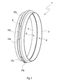
- Fig. 1 to 4 has a compound 1, which serves to connect two axially adjacent ends 2, 3 tubular, here only partially shown body 4, 5 with each other, a centering ring 6 and a clamp 7.
- the clamp 7 is not shown.
- each tube end 2, 3 a radially outwardly projecting annular collar 8 and 9 respectively.
- the respective annular collar 8, 9 projects radially outward from the respective pipe end 2, 3.
- the preferred embodiment shown here is the respective one Ring collar 8, 9 with respect to the respective pipe end 2, 3 each to a separate component which is attached to the respective pipe end 2, 3.
- the respective annular collar 8, 9 is in this case designed C-shaped and arranged so that it is axially open to the respective other pipe end 2, 3 out.
- annular collar 8, 9 To connect the annular collar 8, 9 with the pipe ends 2, 3 is an end portion 10 and 11 at the respective tube end 2, 3 bent back by 180 ° radially outward, such that thereby a leg of the C-profile of the respective annular collar 8, 9 am Pipe end 2, 3 is clamped.
- the annular collar 8, 9 by rolling at the pipe ends 2, 3 fix.
- the annular collar 8, 9 can be soldered to the pipe ends 2, 3.
- other attachment methods are feasible.
- the centering ring 6 is arranged axially between the pipe ends 2, 3. Furthermore, the centering ring 6 radially on the outside a plurality of collar segments 17. In any case, at least two collar segments 17 are present. In the example shown, six collar segments 17 are provided without limiting the generality. In this case, the centering ring 6 different collar segments 17. The one, designated 17a collar segments are axially on one side of the centering ring 6, while the other, designated 17b collar segments projecting on the other side of the centering ring 6. The various collar segments 17a and 17b are thus axially in opposite directions from the centering ring 6 from.
- the different collar segments 17a, 17b on the centering ring 6 are formed so that they project axially alternately on one side or the other from the centering ring 6.
- the one collar segments 17 a engage over Fig. 3 the annular collar 8 of a pipe end 2 radially outward in the axial direction.
- the other collar segments 17b engage over the annular collar 9 of the other pipe end 3 radially outward and in the axial direction. This results in a radial centering or an axially aligned alignment of the two pipe ends 2, 3 relative to each other, wherein the centering on the annular collar 8, 9 takes place radially outward.
- the clamp 7 is corresponding to the 3 and 4 designed so that it engages over the annular collar 8, 9 and the centering ring 6 radially outward in the axial direction and in the radial direction.
- the clamp 7 for example, a clamping band 12 which can be set under tension with the aid of a corresponding, not shown tensioning device in the circumferential direction, and at least one U-shaped or trough-shaped holding element 13, which engages over the annular collar 8, 9 and at this comes to the plant.
- the clamp 7 is designed so that the introduced into the clamping band 12 tension can be transformed via the at least one retaining element 13 in an axial bias, which biases the two pipe ends 2, 3 via the two annular collar 8, 9 axially to each other.
- the centering ring 6 is designed so that it corresponds in a circular arc of 180 °, which corresponds to Fig. 2 the upper half of the cross section shown, only a single circular segment 17 has, here the circular segment 17 a, which extends continuously over about 180 °.
- the centering ring 6 in such a way that it has a plurality of collar segments 17 in the circular arc of 180 °, but all project from the centering ring 6 on the same side.
- the 180 ° circular arc then contains either only collar segments 17a or only collar segments 17b.
- This embodiment makes it possible to adjust the two pipe ends 2, 3 in the absence of clamp 7 relative to each other in the radial direction. This simplifies the assembly and disassembly or the manufacture and release of the pipe joint 1.
- the pipe joint 1 may preferably have two annular sealing bodies 14, 15.
- the one sealing body 14 is axially supported on the one hand on the one annular collar 8 and on the other hand on one side of the centering ring 6.
- this sealing body 14 can also be supported radially at the pipe end 2, here at the bent-back end section 10.
- the other sealing body 15 is axially supported on the one hand on the other annular collar 9 and on the other hand on the other side of the centering ring 6.
- this sealing body 15 can be radially supported at the respective pipe end 3, here at the bent-back end portion 11 be.
- the respective sealing body 14, 15 is attached to the centering ring 6.
- the sealing bodies 14, 15 are glued to the centering ring 6 or vulcanized thereto or molded into it during its production.
- the annular collar 8, 9 here preferably each have an open towards the centering ring 6 profile, such as a C-profile or a U-profile.
- the respective sealing body 14 engages through the open side of the profile in the respective annular collar 8, 9 a. This results in a particularly stable support for the respective sealing body 14, 15 within the respective annular collar 8, 9.
- the centering ring 6 according to the 3 and 4 an inner cross-section 16 which is dimensioned so that the pipe ends 2, 3 are not supported on each other, but on the centering ring 6.
- the inner cross section 16 of the centering ring 6 is dimensioned approximately the same size as an inner cross section 18 of the respective pipe end 2, 3.
- Fig. 5 can the previously described pipe joint 1, the in Fig. 5 is indicated in each case by the centering ring 6 shown greatly simplified, are used to releasably attach a component 19 to tubular end portions 20 each at a pipe end 21 of a pipe 22.
- the component 19 is thereby incorporated into the pipe 22 and forms together with this a component arrangement 23.
- the component arrangement 23 is an exhaust system of an internal combustion engine.
- the component 19 is a particle filter or any other component to be exchangeably incorporated, which is installed in an exhaust pipe, here in the pipe 22.
- the centering rings 6 are oriented so that the respective 180 ° circular arc are aligned approximately the same in terms of their rotational position and that the collar segments 17 a of these 180 ° circular arc projecting toward each other from the respective centering ring 6.
- the centering rings 6 can also be arranged so that the collar segments 17a of these 180 ° circular arc protrude away from the respective centering ring 6.
- This design makes it possible to remove the component 19 with dissolved clamps 7, in the radial direction, ie according to an arrow 25 from the pipe 22, with or without the centering 6.
- no axial adjustment of the two pipe ends 21 of the pipe 22 is required, which the expansion and installation of the component 19 considerably simplified.
- the component 19 can be moved radially into the gap between the tube ends 21 for its installation opposite to the arrow 25.
Landscapes
- Engineering & Computer Science (AREA)
- General Engineering & Computer Science (AREA)
- Mechanical Engineering (AREA)
- Flanged Joints, Insulating Joints, And Other Joints (AREA)
- Quick-Acting Or Multi-Walled Pipe Joints (AREA)
- Mutual Connection Of Rods And Tubes (AREA)
- Non-Disconnectible Joints And Screw-Threaded Joints (AREA)
- Branch Pipes, Bends, And The Like (AREA)
- Joints Allowing Movement (AREA)
Claims (10)
- Liaison pour deux extrémités (2, 3) voisines axialement de respectivement un corps (4, 5) tubulaire, en particulier d'une installation d'échappement,- chaque extrémité de tube (2, 3) présentant une collerette annulaire (8, 9) dépassant radialement à l'extérieur,caractérisée en ce qu'une bague de centrage (6) est prévue, laquelle est disposée axialement entre les extrémités de tube (2, 3) et qui présente radialement à l'extérieur plusieurs segments de collerette (17),- les segments de collerette (17a) dépassant axialement sur un côté de la bague de centrage (6) et recouvrant axialement la collerette annulaire (8) de l'une des extrémités de tube (2) radialement à l'extérieur,- les autres segments de collerette (17b) dépassant axialement sur l'autre côté de la bague de centrage (6) et recouvrant axialement la collerette annulaire (9) de l'autre extrémité de tube (3) radialement à l'extérieur,- une bride (7) étant prévue, laquelle recouvre radialement à l'extérieur les collerettes annulaires (8, 9) et la bague de centrage (6) axialement et radialement.
- Liaison selon la revendication 1,
caractérisée en ce que
la bague de centrage (6) présente dans un arc de cercle de 180° un unique segment de collerette (17a) ou plusieurs segments de collerette (17a, 17b) dépassant respectivement sur le même côté. - Liaison selon la revendication 1 ou 2,
caractérisée en ce que
deux corps d'étanchéité (14, 15) de forme annulaire sont prévus, dont l'un est soutenu axialement d'une part sur l'une des collerettes annulaires (8) et d'autre part sur l'un des côtés de la bague de centrage (6) et dont l'autre est soutenu d'une part sur l'autre collerette annulaire (9) et d'autre part sur l'autre côté de la bague de centrage (6). - Liaison selon la revendication 3,
caractérisée en ce que
les corps d'étanchéité (14, 15) sont fixés sur la bague de centrage (6). - Liaison selon l'une quelconque des revendications 1 à 4,
caractérisée en ce que
au moins l'une des collerettes annulaires (8, 9) présente un profilé ouvert en direction de la bague de centrage (6), dans laquelle en particulier le corps d'étanchéité (14, 15) respectif peut s'engager. - Liaison selon l'une quelconque des revendications 1 à 5,
caractérisée en ce que- au moins l'une des collerettes annulaires (8, 9) est conçue intégralement sur l'extrémité de tube (2, 3) respective, et/ou- en ce qu'au moins l'une des collerettes annulaires (8, 9) est conçue par rapport à l'extrémité de tube (2, 3) respective sous forme de composant séparé, lequel est rapporté à l'extrémité de tube (2, 3) respective, en particulier par roulement. - Liaison selon l'une quelconque des revendications 1 à 6,
caractérisée en ce que- une section intérieure (16) de la bague de centrage (6) est dimensionnée de telle sorte que les extrémités de tube (2, 3) s'appuient axialement sur la bague de centrage (6), et/ou- en ce qu'une section intérieure (16) de la bague de centrage (6) est dimensionnée à peu près aussi grande que les sections intérieures (18) des extrémités de tube (2, 3). - Liaison selon l'une quelconque des revendications 1 à 7,
caractérisée en ce que
les segments de collerette (17a, 17b) débordent l'une de l'autre axialement de la bague de centrage (6) alternativement sur un côté et sur l'autre côté. - Agencement de composant, en particulier installation de gaz d'échappement, comprenant un composant (19) qui présente des parties d'extrémité (20) de forme tubulaire et qui est fixé sur ses parties d'extrémité (20) avec respectivement une liaison (1) selon la revendication 2 sur respectivement une extrémité de tube (21), les bagues de centrage (6) des deux liaisons (1) étant orientées de telle sorte que les arcs de cercle de 180° respectifs sont orientés à peu près de façon identique en ce qui concerne leur position d'orientation et en ce que les segments de collerette (17a) de ces arcs de cercle de 180° débordent de la bague de centrage (6) respective les uns vers les autres ou à partir les uns des autres.
- Agencement de composant selon la revendication 9, caractérisé par les caractéristiques de nouveauté d'au moins l'une des revendications 3 à 8.
Applications Claiming Priority (1)
| Application Number | Priority Date | Filing Date | Title |
|---|---|---|---|
| DE102007033658A DE102007033658A1 (de) | 2007-07-17 | 2007-07-17 | Rohrverbindung und Bauteilanordnung mit Rohrverbindung |
Publications (2)
| Publication Number | Publication Date |
|---|---|
| EP2017516A1 EP2017516A1 (fr) | 2009-01-21 |
| EP2017516B1 true EP2017516B1 (fr) | 2009-12-09 |
Family
ID=39877402
Family Applications (1)
| Application Number | Title | Priority Date | Filing Date |
|---|---|---|---|
| EP08159509A Not-in-force EP2017516B1 (fr) | 2007-07-17 | 2008-07-02 | Raccord de tuyauterie et agencement de composant doté d'un raccord de tuyauterie |
Country Status (4)
| Country | Link |
|---|---|
| US (1) | US7784839B2 (fr) |
| EP (1) | EP2017516B1 (fr) |
| AT (1) | ATE451578T1 (fr) |
| DE (2) | DE102007033658A1 (fr) |
Families Citing this family (1)
| Publication number | Priority date | Publication date | Assignee | Title |
|---|---|---|---|---|
| DE102009007391A1 (de) * | 2009-02-05 | 2010-08-12 | J. Eberspächer GmbH & Co. KG | Abgasreinigungseinrichtung, Abgasanlage und Schellenverbindung |
Family Cites Families (17)
| Publication number | Priority date | Publication date | Assignee | Title |
|---|---|---|---|---|
| US2439254A (en) * | 1944-06-19 | 1948-04-06 | Joseph H Levin | Joint for air ducts and the like |
| DE1054296B (de) * | 1955-10-20 | 1959-04-02 | Aeroquip Corp | Dichtring |
| US2926936A (en) * | 1957-11-14 | 1960-03-01 | Washington Machine & Tool Work | Servomotor gear head coupling |
| DE1953035U (de) * | 1966-07-05 | 1967-01-05 | Heraeus Hochvakuum G M B H | Hochvakuum-dichtscheibe, insbesondere fuer ausheizbare hochvakuum-flanschverbindungen. |
| US3473829A (en) * | 1967-05-08 | 1969-10-21 | Dennis Daniels | Inflatable connector |
| US3630549A (en) * | 1970-01-22 | 1971-12-28 | John A Grimm | Frame and cleat joint connector for ducts |
| US3669474A (en) * | 1970-08-26 | 1972-06-13 | Richard M Bode | Coupled joint of axially aligned elongated members |
| DE7205640U (de) * | 1971-02-17 | 1974-12-05 | Moldow P | Verbindungseinrichtung für rohrförmige Kanalelemente |
| CH640922A5 (de) * | 1979-10-22 | 1984-01-31 | Balzers Hochvakuum | Dichtung fuer vakuumflanschverbindungen. |
| DE3744045A1 (de) * | 1987-12-24 | 1989-07-06 | Linnemann Friedrich | Verbindung |
| US5135270A (en) * | 1988-06-10 | 1992-08-04 | Ductmate Industries, Inc. | Apparatus for connecting the ends of a pair of oval duct sections |
| US4986574A (en) * | 1990-01-11 | 1991-01-22 | Fisher Controls International, Inc. | Raised face flange alignment tool |
| WO1998029679A1 (fr) * | 1997-01-03 | 1998-07-09 | Seetru Limited | Joints de conduits, conduits et systemes de canalisation incorporant ces joints |
| US6481911B1 (en) * | 1999-11-24 | 2002-11-19 | Fritz Michael Streuber | Jointing method for joining preformed bodies |
| US6857638B2 (en) * | 2003-02-14 | 2005-02-22 | Rubber Fab, Inc. | Gasket for sanitary fittings |
| US20040262922A1 (en) * | 2003-06-27 | 2004-12-30 | Lindab Ab | Assembly system for a pipe coupling |
| IES20050246A2 (en) * | 2005-04-25 | 2006-11-01 | Aidan Casey Senior | A clamp |
-
2007
- 2007-07-17 DE DE102007033658A patent/DE102007033658A1/de not_active Withdrawn
-
2008
- 2008-07-02 AT AT08159509T patent/ATE451578T1/de active
- 2008-07-02 DE DE502008000241T patent/DE502008000241D1/de active Active
- 2008-07-02 EP EP08159509A patent/EP2017516B1/fr not_active Not-in-force
- 2008-07-16 US US12/174,005 patent/US7784839B2/en active Active
Also Published As
| Publication number | Publication date |
|---|---|
| DE102007033658A1 (de) | 2009-01-22 |
| ATE451578T1 (de) | 2009-12-15 |
| DE502008000241D1 (de) | 2010-01-21 |
| US20090021004A1 (en) | 2009-01-22 |
| EP2017516A1 (fr) | 2009-01-21 |
| US7784839B2 (en) | 2010-08-31 |
Similar Documents
| Publication | Publication Date | Title |
|---|---|---|
| EP2420656B1 (fr) | Dispositif de nettoyage des gaz d'échappement, installation de gaz d'échappement, procédé de démontage | |
| EP1887194A1 (fr) | Dispositif de purification de gas d'échappement | |
| EP2216525B1 (fr) | Dispositif de purification des gaz d'échappement, système de gaz d'échappement et connexion par serrage | |
| DE102021115904A1 (de) | Flanschverbindungsanordnung für eine rohrleitung | |
| EP3412879B1 (fr) | Dispositif de post-traitement de gaz d'échappement d'un moteur à combustion interne d'un véhicule automobile | |
| DE29606683U1 (de) | Anschlußverbindung zwischen einem Bauteil und einem rohrförmigen Leitungselement | |
| EP2017516B1 (fr) | Raccord de tuyauterie et agencement de composant doté d'un raccord de tuyauterie | |
| DE102005057670B4 (de) | Rohrverbindung | |
| EP3724470A1 (fr) | Dispositif et procédé de raccordement de composants de conduite de fluide, en particulier dans la ligne de gaz d'échappement d'un véhicule automobile | |
| DE2614477A1 (de) | Loesbare rohrverbindung, insbesondere fuer mehrteilige fahrzeugauspuffrohre | |
| WO2019011463A1 (fr) | Dispositif de liaison pour turbocompresseur et turbocompresseur | |
| EP4198371B1 (fr) | Compensateur de pipeline industriel | |
| EP1248027A1 (fr) | Raccord axial de deux éléments tubulaires | |
| EP0889271A2 (fr) | Raccord entre deux tuyaux emboítés | |
| EP3584487B1 (fr) | Système de gaz d'échappement avec bride tubulaire | |
| EP2865944B1 (fr) | Bride tubulaire pour tuyaux d'air de combustion ainsi que système de tuyau d'échappement | |
| EP0654599B1 (fr) | Dispositif de recirculation des gaz d'échappement | |
| DE102022120822B3 (de) | Rohrverbindungsanordnung mit einem Mantelrohr und Brennkraftmaschine mit einer solchen Rohrverbindungsanordnung | |
| WO2016037686A1 (fr) | Turbocompresseur à gaz d'échappement | |
| DE102008012779B4 (de) | Leitungsverbindung einer Einrichtung zur Abgasrückführung | |
| EP1686303A1 (fr) | Raccord démontable pour éléments profilés avec anneau de centrage | |
| DE19816862C2 (de) | Lösbare Rohrverbindung | |
| DE102009007766A1 (de) | Einrichtung und Verfahren zum Verbinden zweier Verbindungselemente auf Seiten von Abgasbehandlungseinheiten und Abgastrakt | |
| DE102004056792B4 (de) | Rohrverbindung | |
| EP3045795B1 (fr) | Raccord de tuyauterie |
Legal Events
| Date | Code | Title | Description |
|---|---|---|---|
| PUAI | Public reference made under article 153(3) epc to a published international application that has entered the european phase |
Free format text: ORIGINAL CODE: 0009012 |
|
| AK | Designated contracting states |
Kind code of ref document: A1 Designated state(s): AT BE BG CH CY CZ DE DK EE ES FI FR GB GR HR HU IE IS IT LI LT LU LV MC MT NL NO PL PT RO SE SI SK TR |
|
| AX | Request for extension of the european patent |
Extension state: AL BA MK RS |
|
| GRAP | Despatch of communication of intention to grant a patent |
Free format text: ORIGINAL CODE: EPIDOSNIGR1 |
|
| 17P | Request for examination filed |
Effective date: 20090721 |
|
| AKX | Designation fees paid |
Designated state(s): AT BE BG CH CY CZ DE DK EE ES FI FR GB GR HR HU IE IS IT LI LT LU LV MC MT NL NO PL PT RO SE SI SK TR |
|
| GRAS | Grant fee paid |
Free format text: ORIGINAL CODE: EPIDOSNIGR3 |
|
| GRAA | (expected) grant |
Free format text: ORIGINAL CODE: 0009210 |
|
| AK | Designated contracting states |
Kind code of ref document: B1 Designated state(s): AT BE BG CH CY CZ DE DK EE ES FI FR GB GR HR HU IE IS IT LI LT LU LV MC MT NL NO PL PT RO SE SI SK TR |
|
| REG | Reference to a national code |
Ref country code: GB Ref legal event code: FG4D Free format text: NOT ENGLISH |
|
| REG | Reference to a national code |
Ref country code: CH Ref legal event code: EP |
|
| REG | Reference to a national code |
Ref country code: IE Ref legal event code: FG4D |
|
| REF | Corresponds to: |
Ref document number: 502008000241 Country of ref document: DE Date of ref document: 20100121 Kind code of ref document: P |
|
| REG | Reference to a national code |
Ref country code: SE Ref legal event code: TRGR |
|
| REG | Reference to a national code |
Ref country code: NL Ref legal event code: VDEP Effective date: 20091209 |
|
| PG25 | Lapsed in a contracting state [announced via postgrant information from national office to epo] |
Ref country code: NO Free format text: LAPSE BECAUSE OF FAILURE TO SUBMIT A TRANSLATION OF THE DESCRIPTION OR TO PAY THE FEE WITHIN THE PRESCRIBED TIME-LIMIT Effective date: 20100309 Ref country code: LT Free format text: LAPSE BECAUSE OF FAILURE TO SUBMIT A TRANSLATION OF THE DESCRIPTION OR TO PAY THE FEE WITHIN THE PRESCRIBED TIME-LIMIT Effective date: 20091209 Ref country code: FI Free format text: LAPSE BECAUSE OF FAILURE TO SUBMIT A TRANSLATION OF THE DESCRIPTION OR TO PAY THE FEE WITHIN THE PRESCRIBED TIME-LIMIT Effective date: 20091209 |
|
| LTIE | Lt: invalidation of european patent or patent extension |
Effective date: 20091209 |
|
| PG25 | Lapsed in a contracting state [announced via postgrant information from national office to epo] |
Ref country code: HR Free format text: LAPSE BECAUSE OF FAILURE TO SUBMIT A TRANSLATION OF THE DESCRIPTION OR TO PAY THE FEE WITHIN THE PRESCRIBED TIME-LIMIT Effective date: 20091209 Ref country code: LV Free format text: LAPSE BECAUSE OF FAILURE TO SUBMIT A TRANSLATION OF THE DESCRIPTION OR TO PAY THE FEE WITHIN THE PRESCRIBED TIME-LIMIT Effective date: 20091209 Ref country code: SI Free format text: LAPSE BECAUSE OF FAILURE TO SUBMIT A TRANSLATION OF THE DESCRIPTION OR TO PAY THE FEE WITHIN THE PRESCRIBED TIME-LIMIT Effective date: 20091209 Ref country code: PL Free format text: LAPSE BECAUSE OF FAILURE TO SUBMIT A TRANSLATION OF THE DESCRIPTION OR TO PAY THE FEE WITHIN THE PRESCRIBED TIME-LIMIT Effective date: 20091209 |
|
| REG | Reference to a national code |
Ref country code: IE Ref legal event code: FD4D |
|
| PG25 | Lapsed in a contracting state [announced via postgrant information from national office to epo] |
Ref country code: RO Free format text: LAPSE BECAUSE OF FAILURE TO SUBMIT A TRANSLATION OF THE DESCRIPTION OR TO PAY THE FEE WITHIN THE PRESCRIBED TIME-LIMIT Effective date: 20091209 Ref country code: ES Free format text: LAPSE BECAUSE OF FAILURE TO SUBMIT A TRANSLATION OF THE DESCRIPTION OR TO PAY THE FEE WITHIN THE PRESCRIBED TIME-LIMIT Effective date: 20100320 Ref country code: BG Free format text: LAPSE BECAUSE OF FAILURE TO SUBMIT A TRANSLATION OF THE DESCRIPTION OR TO PAY THE FEE WITHIN THE PRESCRIBED TIME-LIMIT Effective date: 20100309 Ref country code: EE Free format text: LAPSE BECAUSE OF FAILURE TO SUBMIT A TRANSLATION OF THE DESCRIPTION OR TO PAY THE FEE WITHIN THE PRESCRIBED TIME-LIMIT Effective date: 20091209 Ref country code: IS Free format text: LAPSE BECAUSE OF FAILURE TO SUBMIT A TRANSLATION OF THE DESCRIPTION OR TO PAY THE FEE WITHIN THE PRESCRIBED TIME-LIMIT Effective date: 20100409 Ref country code: IE Free format text: LAPSE BECAUSE OF FAILURE TO SUBMIT A TRANSLATION OF THE DESCRIPTION OR TO PAY THE FEE WITHIN THE PRESCRIBED TIME-LIMIT Effective date: 20091209 Ref country code: NL Free format text: LAPSE BECAUSE OF FAILURE TO SUBMIT A TRANSLATION OF THE DESCRIPTION OR TO PAY THE FEE WITHIN THE PRESCRIBED TIME-LIMIT Effective date: 20091209 |
|
| PG25 | Lapsed in a contracting state [announced via postgrant information from national office to epo] |
Ref country code: SK Free format text: LAPSE BECAUSE OF FAILURE TO SUBMIT A TRANSLATION OF THE DESCRIPTION OR TO PAY THE FEE WITHIN THE PRESCRIBED TIME-LIMIT Effective date: 20091209 Ref country code: CZ Free format text: LAPSE BECAUSE OF FAILURE TO SUBMIT A TRANSLATION OF THE DESCRIPTION OR TO PAY THE FEE WITHIN THE PRESCRIBED TIME-LIMIT Effective date: 20091209 |
|
| PLBE | No opposition filed within time limit |
Free format text: ORIGINAL CODE: 0009261 |
|
| STAA | Information on the status of an ep patent application or granted ep patent |
Free format text: STATUS: NO OPPOSITION FILED WITHIN TIME LIMIT |
|
| PG25 | Lapsed in a contracting state [announced via postgrant information from national office to epo] |
Ref country code: GR Free format text: LAPSE BECAUSE OF FAILURE TO SUBMIT A TRANSLATION OF THE DESCRIPTION OR TO PAY THE FEE WITHIN THE PRESCRIBED TIME-LIMIT Effective date: 20100310 Ref country code: CY Free format text: LAPSE BECAUSE OF FAILURE TO SUBMIT A TRANSLATION OF THE DESCRIPTION OR TO PAY THE FEE WITHIN THE PRESCRIBED TIME-LIMIT Effective date: 20091209 |
|
| 26N | No opposition filed |
Effective date: 20100910 |
|
| BERE | Be: lapsed |
Owner name: J. EBERSPACHER G.M.B.H. & CO. KG Effective date: 20100731 |
|
| PG25 | Lapsed in a contracting state [announced via postgrant information from national office to epo] |
Ref country code: DK Free format text: LAPSE BECAUSE OF FAILURE TO SUBMIT A TRANSLATION OF THE DESCRIPTION OR TO PAY THE FEE WITHIN THE PRESCRIBED TIME-LIMIT Effective date: 20091209 |
|
| PG25 | Lapsed in a contracting state [announced via postgrant information from national office to epo] |
Ref country code: MC Free format text: LAPSE BECAUSE OF NON-PAYMENT OF DUE FEES Effective date: 20100731 |
|
| PG25 | Lapsed in a contracting state [announced via postgrant information from national office to epo] |
Ref country code: IT Free format text: LAPSE BECAUSE OF FAILURE TO SUBMIT A TRANSLATION OF THE DESCRIPTION OR TO PAY THE FEE WITHIN THE PRESCRIBED TIME-LIMIT Effective date: 20091209 |
|
| PG25 | Lapsed in a contracting state [announced via postgrant information from national office to epo] |
Ref country code: BE Free format text: LAPSE BECAUSE OF NON-PAYMENT OF DUE FEES Effective date: 20100731 |
|
| PG25 | Lapsed in a contracting state [announced via postgrant information from national office to epo] |
Ref country code: MT Free format text: LAPSE BECAUSE OF FAILURE TO SUBMIT A TRANSLATION OF THE DESCRIPTION OR TO PAY THE FEE WITHIN THE PRESCRIBED TIME-LIMIT Effective date: 20091209 |
|
| PG25 | Lapsed in a contracting state [announced via postgrant information from national office to epo] |
Ref country code: LU Free format text: LAPSE BECAUSE OF NON-PAYMENT OF DUE FEES Effective date: 20100702 Ref country code: HU Free format text: LAPSE BECAUSE OF FAILURE TO SUBMIT A TRANSLATION OF THE DESCRIPTION OR TO PAY THE FEE WITHIN THE PRESCRIBED TIME-LIMIT Effective date: 20100610 Ref country code: PT Free format text: LAPSE BECAUSE OF FAILURE TO SUBMIT A TRANSLATION OF THE DESCRIPTION OR TO PAY THE FEE WITHIN THE PRESCRIBED TIME-LIMIT Effective date: 20100509 |
|
| PG25 | Lapsed in a contracting state [announced via postgrant information from national office to epo] |
Ref country code: TR Free format text: LAPSE BECAUSE OF FAILURE TO SUBMIT A TRANSLATION OF THE DESCRIPTION OR TO PAY THE FEE WITHIN THE PRESCRIBED TIME-LIMIT Effective date: 20091209 |
|
| REG | Reference to a national code |
Ref country code: CH Ref legal event code: PL |
|
| PG25 | Lapsed in a contracting state [announced via postgrant information from national office to epo] |
Ref country code: CH Free format text: LAPSE BECAUSE OF NON-PAYMENT OF DUE FEES Effective date: 20120731 Ref country code: LI Free format text: LAPSE BECAUSE OF NON-PAYMENT OF DUE FEES Effective date: 20120731 |
|
| REG | Reference to a national code |
Ref country code: GB Ref legal event code: 732E Free format text: REGISTERED BETWEEN 20130905 AND 20130911 |
|
| REG | Reference to a national code |
Ref country code: DE Ref legal event code: R082 Ref document number: 502008000241 Country of ref document: DE Representative=s name: BRP RENAUD & PARTNER, DE |
|
| REG | Reference to a national code |
Ref country code: DE Ref legal event code: R082 Ref document number: 502008000241 Country of ref document: DE Representative=s name: BRP RENAUD UND PARTNER MBB, DE Effective date: 20131022 Ref country code: DE Ref legal event code: R082 Ref document number: 502008000241 Country of ref document: DE Representative=s name: BRP RENAUD UND PARTNER MBB RECHTSANWAELTE PATE, DE Effective date: 20131022 Ref country code: DE Ref legal event code: R081 Ref document number: 502008000241 Country of ref document: DE Owner name: EBERSPAECHER EXHAUST TECHNOLOGY GMBH & CO. KG, DE Free format text: FORMER OWNER: J. EBERSPAECHER GMBH & CO. KG, 73730 ESSLINGEN, DE Effective date: 20131022 Ref country code: DE Ref legal event code: R082 Ref document number: 502008000241 Country of ref document: DE Representative=s name: BRP RENAUD & PARTNER, DE Effective date: 20131022 |
|
| REG | Reference to a national code |
Ref country code: FR Ref legal event code: CD Owner name: EBERSPACHER CLIMATE CONTROL SYSTEMS GMBH & CO. KG Effective date: 20131129 |
|
| REG | Reference to a national code |
Ref country code: FR Ref legal event code: TP Owner name: EBERSPACHER EXHAUST TECHNOLOGY GMBH & CO. KG, DE Effective date: 20140204 |
|
| REG | Reference to a national code |
Ref country code: AT Ref legal event code: MM01 Ref document number: 451578 Country of ref document: AT Kind code of ref document: T Effective date: 20130702 |
|
| PG25 | Lapsed in a contracting state [announced via postgrant information from national office to epo] |
Ref country code: AT Free format text: LAPSE BECAUSE OF NON-PAYMENT OF DUE FEES Effective date: 20130702 |
|
| REG | Reference to a national code |
Ref country code: FR Ref legal event code: PLFP Year of fee payment: 9 |
|
| REG | Reference to a national code |
Ref country code: FR Ref legal event code: PLFP Year of fee payment: 10 |
|
| REG | Reference to a national code |
Ref country code: FR Ref legal event code: PLFP Year of fee payment: 11 |
|
| REG | Reference to a national code |
Ref country code: DE Ref legal event code: R081 Ref document number: 502008000241 Country of ref document: DE Owner name: PUREM GMBH, DE Free format text: FORMER OWNER: EBERSPAECHER EXHAUST TECHNOLOGY GMBH & CO. KG, 66539 NEUNKIRCHEN, DE |
|
| PGFP | Annual fee paid to national office [announced via postgrant information from national office to epo] |
Ref country code: SE Payment date: 20220721 Year of fee payment: 15 |
|
| PGFP | Annual fee paid to national office [announced via postgrant information from national office to epo] |
Ref country code: GB Payment date: 20230724 Year of fee payment: 16 |
|
| PGFP | Annual fee paid to national office [announced via postgrant information from national office to epo] |
Ref country code: FR Payment date: 20230724 Year of fee payment: 16 Ref country code: DE Payment date: 20230720 Year of fee payment: 16 |
|
| REG | Reference to a national code |
Ref country code: SE Ref legal event code: EUG |
|
| PG25 | Lapsed in a contracting state [announced via postgrant information from national office to epo] |
Ref country code: SE Free format text: LAPSE BECAUSE OF NON-PAYMENT OF DUE FEES Effective date: 20230703 |
|
| REG | Reference to a national code |
Ref country code: DE Ref legal event code: R119 Ref document number: 502008000241 Country of ref document: DE |
|
| GBPC | Gb: european patent ceased through non-payment of renewal fee |
Effective date: 20240702 |
|
| PG25 | Lapsed in a contracting state [announced via postgrant information from national office to epo] |
Ref country code: DE Free format text: LAPSE BECAUSE OF NON-PAYMENT OF DUE FEES Effective date: 20250201 |
|
| PG25 | Lapsed in a contracting state [announced via postgrant information from national office to epo] |
Ref country code: FR Free format text: LAPSE BECAUSE OF NON-PAYMENT OF DUE FEES Effective date: 20240731 |
|
| PG25 | Lapsed in a contracting state [announced via postgrant information from national office to epo] |
Ref country code: GB Free format text: LAPSE BECAUSE OF NON-PAYMENT OF DUE FEES Effective date: 20240702 |