EP2017516B1 - Tube connection and component assembly with tube connection - Google Patents
Tube connection and component assembly with tube connection Download PDFInfo
- Publication number
- EP2017516B1 EP2017516B1 EP08159509A EP08159509A EP2017516B1 EP 2017516 B1 EP2017516 B1 EP 2017516B1 EP 08159509 A EP08159509 A EP 08159509A EP 08159509 A EP08159509 A EP 08159509A EP 2017516 B1 EP2017516 B1 EP 2017516B1
- Authority
- EP
- European Patent Office
- Prior art keywords
- ring
- axially
- collar
- centring ring
- pipe
- Prior art date
- Legal status (The legal status is an assumption and is not a legal conclusion. Google has not performed a legal analysis and makes no representation as to the accuracy of the status listed.)
- Not-in-force
Links
- 238000007789 sealing Methods 0.000 claims description 15
- 238000005096 rolling process Methods 0.000 claims description 2
- 230000001747 exhibiting effect Effects 0.000 abstract 1
- 239000002245 particle Substances 0.000 description 4
- 238000009434 installation Methods 0.000 description 3
- 238000004519 manufacturing process Methods 0.000 description 3
- 238000002485 combustion reaction Methods 0.000 description 2
- 230000001419 dependent effect Effects 0.000 description 2
- 230000002093 peripheral effect Effects 0.000 description 2
- 229940125904 compound 1 Drugs 0.000 description 1
- 150000001875 compounds Chemical class 0.000 description 1
- 238000002955 isolation Methods 0.000 description 1
- 238000000034 method Methods 0.000 description 1
Images


Classifications
-
- F—MECHANICAL ENGINEERING; LIGHTING; HEATING; WEAPONS; BLASTING
- F16—ENGINEERING ELEMENTS AND UNITS; GENERAL MEASURES FOR PRODUCING AND MAINTAINING EFFECTIVE FUNCTIONING OF MACHINES OR INSTALLATIONS; THERMAL INSULATION IN GENERAL
- F16L—PIPES; JOINTS OR FITTINGS FOR PIPES; SUPPORTS FOR PIPES, CABLES OR PROTECTIVE TUBING; MEANS FOR THERMAL INSULATION IN GENERAL
- F16L23/00—Flanged joints
- F16L23/003—Auxiliary devices
Definitions
- the present invention relates to a connection for two axially adjacent ends of a tubular body, in particular an exhaust system.
- the invention also relates to a component arrangement, in particular an exhaust system, in which a component which has tubular end sections is fastened at these end sections, each with such a pipe connection, to pipe ends.
- WO 2006/114780-A discloses a connection of two pipe ends, each pipe end having a radially outwardly projecting annular flange.
- a component which can be flowed through with an infeed pipe and with a discharge pipe it may be necessary to releasably connect a component which can be flowed through with an infeed pipe and with a discharge pipe.
- a particle filter from the exhaust gas line, for example in order to be able to exchange or clean the respective particle filter element. Desirable is ease of handling with sufficient reliability in terms of tightness and temperature resistance.
- the present invention is concerned with the problem for a connection or for a component arrangement of the above mentioned type to provide an improved embodiment, which is characterized in particular by a simplified assembly and disassembly.
- the invention is based on the general idea of equipping the respective pipe joint with a centering ring, which is arranged axially between the pipe ends to be joined together and radially outwardly comprises a plurality of collar segments, one of which axially protrude on one side of the centering ring and of which others protrude axially on the other side of the centering ring.
- a clamp is provided, the radially outside the annular collar of the pipe ends and the centering axially and radially overlaps.
- the collar segments engage over the tube ends to be joined together radially in the axial direction. In this way, an external centering of the two pipe ends to be joined together can be achieved.
- the centering ring in a circular arc of 180 ° either only a single collar segment or more, each projecting on the same side collar segments.
- This special design makes it possible to adjust the two axially adjacent pipe ends relative to each other radially in the absence of clamp. This results in the possibility for a component which is integrated at its axial ends in each case with such a pipe connection in a pipeline with open clamps radially out of this pipe, without it being necessary, the pipe ends, between which the respective component in the pipeline is bound to move axially relative to each other. As a result, the installation and removal of the respective component is considerably simplified. For example, a particle filter can thus be removed radially from the associated exhaust line without the exhaust pipe having to be moved in the axial direction for this purpose.
- two annular sealing body may be provided, of which one is axially supported on the one hand on the one annular collar and on the other hand on one side of the centering ring and of which the other on the one hand on the other ring collar and on the other hand axially supported on the other side of the centering ring.
- the sealing body With the help of the sealing body, an effective gas-tightness of the pipe joint can be realized.
- an embodiment in which the sealing bodies are fastened to the centering ring is particularly advantageous. On the one hand, this considerably simplifies the assembly of the pipe connection.
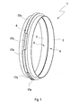
- Fig. 1 to 4 has a compound 1, which serves to connect two axially adjacent ends 2, 3 tubular, here only partially shown body 4, 5 with each other, a centering ring 6 and a clamp 7.
- the clamp 7 is not shown.
- each tube end 2, 3 a radially outwardly projecting annular collar 8 and 9 respectively.
- the respective annular collar 8, 9 projects radially outward from the respective pipe end 2, 3.
- the preferred embodiment shown here is the respective one Ring collar 8, 9 with respect to the respective pipe end 2, 3 each to a separate component which is attached to the respective pipe end 2, 3.
- the respective annular collar 8, 9 is in this case designed C-shaped and arranged so that it is axially open to the respective other pipe end 2, 3 out.
- annular collar 8, 9 To connect the annular collar 8, 9 with the pipe ends 2, 3 is an end portion 10 and 11 at the respective tube end 2, 3 bent back by 180 ° radially outward, such that thereby a leg of the C-profile of the respective annular collar 8, 9 am Pipe end 2, 3 is clamped.
- the annular collar 8, 9 by rolling at the pipe ends 2, 3 fix.
- the annular collar 8, 9 can be soldered to the pipe ends 2, 3.
- other attachment methods are feasible.
- the centering ring 6 is arranged axially between the pipe ends 2, 3. Furthermore, the centering ring 6 radially on the outside a plurality of collar segments 17. In any case, at least two collar segments 17 are present. In the example shown, six collar segments 17 are provided without limiting the generality. In this case, the centering ring 6 different collar segments 17. The one, designated 17a collar segments are axially on one side of the centering ring 6, while the other, designated 17b collar segments projecting on the other side of the centering ring 6. The various collar segments 17a and 17b are thus axially in opposite directions from the centering ring 6 from.
- the different collar segments 17a, 17b on the centering ring 6 are formed so that they project axially alternately on one side or the other from the centering ring 6.
- the one collar segments 17 a engage over Fig. 3 the annular collar 8 of a pipe end 2 radially outward in the axial direction.
- the other collar segments 17b engage over the annular collar 9 of the other pipe end 3 radially outward and in the axial direction. This results in a radial centering or an axially aligned alignment of the two pipe ends 2, 3 relative to each other, wherein the centering on the annular collar 8, 9 takes place radially outward.
- the clamp 7 is corresponding to the 3 and 4 designed so that it engages over the annular collar 8, 9 and the centering ring 6 radially outward in the axial direction and in the radial direction.
- the clamp 7 for example, a clamping band 12 which can be set under tension with the aid of a corresponding, not shown tensioning device in the circumferential direction, and at least one U-shaped or trough-shaped holding element 13, which engages over the annular collar 8, 9 and at this comes to the plant.
- the clamp 7 is designed so that the introduced into the clamping band 12 tension can be transformed via the at least one retaining element 13 in an axial bias, which biases the two pipe ends 2, 3 via the two annular collar 8, 9 axially to each other.
- the centering ring 6 is designed so that it corresponds in a circular arc of 180 °, which corresponds to Fig. 2 the upper half of the cross section shown, only a single circular segment 17 has, here the circular segment 17 a, which extends continuously over about 180 °.
- the centering ring 6 in such a way that it has a plurality of collar segments 17 in the circular arc of 180 °, but all project from the centering ring 6 on the same side.
- the 180 ° circular arc then contains either only collar segments 17a or only collar segments 17b.
- This embodiment makes it possible to adjust the two pipe ends 2, 3 in the absence of clamp 7 relative to each other in the radial direction. This simplifies the assembly and disassembly or the manufacture and release of the pipe joint 1.
- the pipe joint 1 may preferably have two annular sealing bodies 14, 15.
- the one sealing body 14 is axially supported on the one hand on the one annular collar 8 and on the other hand on one side of the centering ring 6.
- this sealing body 14 can also be supported radially at the pipe end 2, here at the bent-back end section 10.
- the other sealing body 15 is axially supported on the one hand on the other annular collar 9 and on the other hand on the other side of the centering ring 6.
- this sealing body 15 can be radially supported at the respective pipe end 3, here at the bent-back end portion 11 be.
- the respective sealing body 14, 15 is attached to the centering ring 6.
- the sealing bodies 14, 15 are glued to the centering ring 6 or vulcanized thereto or molded into it during its production.
- the annular collar 8, 9 here preferably each have an open towards the centering ring 6 profile, such as a C-profile or a U-profile.
- the respective sealing body 14 engages through the open side of the profile in the respective annular collar 8, 9 a. This results in a particularly stable support for the respective sealing body 14, 15 within the respective annular collar 8, 9.
- the centering ring 6 according to the 3 and 4 an inner cross-section 16 which is dimensioned so that the pipe ends 2, 3 are not supported on each other, but on the centering ring 6.
- the inner cross section 16 of the centering ring 6 is dimensioned approximately the same size as an inner cross section 18 of the respective pipe end 2, 3.
- Fig. 5 can the previously described pipe joint 1, the in Fig. 5 is indicated in each case by the centering ring 6 shown greatly simplified, are used to releasably attach a component 19 to tubular end portions 20 each at a pipe end 21 of a pipe 22.
- the component 19 is thereby incorporated into the pipe 22 and forms together with this a component arrangement 23.
- the component arrangement 23 is an exhaust system of an internal combustion engine.
- the component 19 is a particle filter or any other component to be exchangeably incorporated, which is installed in an exhaust pipe, here in the pipe 22.
- the centering rings 6 are oriented so that the respective 180 ° circular arc are aligned approximately the same in terms of their rotational position and that the collar segments 17 a of these 180 ° circular arc projecting toward each other from the respective centering ring 6.
- the centering rings 6 can also be arranged so that the collar segments 17a of these 180 ° circular arc protrude away from the respective centering ring 6.
- This design makes it possible to remove the component 19 with dissolved clamps 7, in the radial direction, ie according to an arrow 25 from the pipe 22, with or without the centering 6.
- no axial adjustment of the two pipe ends 21 of the pipe 22 is required, which the expansion and installation of the component 19 considerably simplified.
- the component 19 can be moved radially into the gap between the tube ends 21 for its installation opposite to the arrow 25.
Landscapes
- Engineering & Computer Science (AREA)
- General Engineering & Computer Science (AREA)
- Mechanical Engineering (AREA)
- Flanged Joints, Insulating Joints, And Other Joints (AREA)
- Quick-Acting Or Multi-Walled Pipe Joints (AREA)
- Mutual Connection Of Rods And Tubes (AREA)
- Non-Disconnectible Joints And Screw-Threaded Joints (AREA)
- Branch Pipes, Bends, And The Like (AREA)
- Joints Allowing Movement (AREA)
Abstract
Description
Die vorliegende Erfindung betrifft eine Verbindung für zwei axial benachbarte Enden eines rohrförmigen Körpers, insbesondere einer Abgasanlage. Die Erfindung betrifft außerdem eine Bauteilanordnung, insbesondere eine Abgasanlage, bei der ein Bauteil, das rohrförmige Endabschnitte aufweist, an diesen Endabschnitten mit jeweils einer derartigen Rohrverbindung an Rohrenden befestigt ist.The present invention relates to a connection for two axially adjacent ends of a tubular body, in particular an exhaust system. The invention also relates to a component arrangement, in particular an exhaust system, in which a component which has tubular end sections is fastened at these end sections, each with such a pipe connection, to pipe ends.
Bei bestimmten Bauteilanordnung, wie z.B. bei einer Abgasanlage, insbesondere einer Brennkraftmaschine, kann es erforderlich sein, ein durchströmbares Bauteil lösbar mit einem zuführenden und mit einem abführenden Rohr zu verbinden. Beispielsweise ist es bei Abgasanlagen erwünscht, ein Partikelfilter aus dem Abgasstrang ausbauen zu können, beispielsweise um das jeweilige Partikelfilterelement austauschen bzw. reinigen zu können. Erwünscht ist dabei eine einfache Handhabbarkeit bei hinreichender Betriebssicherheit hinsichtlich Dichtigkeit und Temperaturbeständigkeit.In certain component arrangements, such as e.g. in an exhaust system, in particular an internal combustion engine, it may be necessary to releasably connect a component which can be flowed through with an infeed pipe and with a discharge pipe. For example, in the case of exhaust systems, it is desirable to be able to remove a particle filter from the exhaust gas line, for example in order to be able to exchange or clean the respective particle filter element. Desirable is ease of handling with sufficient reliability in terms of tightness and temperature resistance.
Die vorliegende Erfindung beschäftigt sich mit dem Problem, für eine Verbindung bzw. für eine Bauteilanordnung der eingangs genannten Art eine verbesserte Ausführungsform anzugeben, die sich insbesondere durch eine vereinfachte Montage und Demontage auszeichnet.The present invention is concerned with the problem for a connection or for a component arrangement of the above mentioned type to provide an improved embodiment, which is characterized in particular by a simplified assembly and disassembly.
Erfindungsgemäß wird dieses Problem durch den Gegenstand des unabhängigen Anspruchs gelöst. Vorteilhafte Ausführungsform sind Gegenstand der abhängigen Ansprüche.According to the invention, this problem is solved by the subject matter of the independent claim. Advantageous embodiments are the subject of the dependent claims.
Die Erfindung beruht auf dem allgemeinen Gedanken, die jeweilige Rohrverbindung mit einem Zentrierring auszustatten, der axial zwischen den miteinander zu verbindenden Rohrenden angeordnet ist und der radial außen mehrere Kragensegmente aufweist, von denen die einen an der einen Seite des Zentrierrings axial abstehen und von denen die anderen an der andere Seite des Zentrierrings axial abstehen. Außerdem wird eine Schelle vorgesehen, die radial außen die Ringkragen der Rohrenden und den Zentrierring axial und radial übergreift. Die Kragensegmente übergreifen dabei die miteinander zu verbindenden Rohrenden radial außen in axialer Richtung. Hierdurch kann eine außenliegende Zentrierung der beiden miteinander zu verbindenden Rohrenden erzielt werden. Dies kann - je nach Ausgestaltung - die Herstellung bzw. das Lösen der jeweiligen Rohrverbindung vereinfachen. Da die Kragensegmente, welche die Zentrierung der beiden Rohrenden bewirken, außerhalb des gasführenden Bereichs der Rohre angeordnet sind, ergibt sich eine reduzierte thermische Belastung der Kragensegmente, wodurch die Verbindung eine erhöhte Zuverlässigkeit besitzt. Desweiteren ist der bezüglich der Rohrenden ein separates Bauteil bildende Zentrierring insbesondere als Ersatzteil konzipiert, und kann somit beim Lösen der Rohrverbindung und beim erneuten Herstellen der Rohrverbindung ersetzt werden. Auch diese Maßnahme erhöht die Zuverlässigkeit der Rohrverbindung.The invention is based on the general idea of equipping the respective pipe joint with a centering ring, which is arranged axially between the pipe ends to be joined together and radially outwardly comprises a plurality of collar segments, one of which axially protrude on one side of the centering ring and of which others protrude axially on the other side of the centering ring. In addition, a clamp is provided, the radially outside the annular collar of the pipe ends and the centering axially and radially overlaps. The collar segments engage over the tube ends to be joined together radially in the axial direction. In this way, an external centering of the two pipe ends to be joined together can be achieved. This can - depending on the configuration - simplify the production or the release of the respective pipe joint. Since the collar segments, which cause the centering of the two pipe ends, are arranged outside the gas-carrying region of the tubes, there is a reduced thermal load on the collar segments, whereby the connection has an increased reliability. Furthermore, with respect to the tube ends a separate component forming centering ring is particular designed as a spare part, and can thus be replaced when loosening the pipe connection and when re-establishing the pipe connection. This measure also increases the reliability of the pipe connection.
Entsprechend einer vorteilhaften Ausführungsform weist der Zentrierring in einem Kreisbogen von 180° entweder nur ein einziges Kragensegment oder mehrere, jeweils an der gleichen Seite abstehende Kragensegmente auf. Diese besondere Bauweise ermöglicht es bei fehlender Schelle die beiden axial benachbarten Rohrenden relativ zueinander radial zu verstellen. Hierdurch ergibt sich die Möglichkeit, bei einem Bauteil, das an seinen axialen Enden jeweils mit einer derartigen Rohrverbindung in eine Rohrleitung eingebunden ist, bei geöffneten Schellen radial aus dieser Rohrleitung herauszunehmen, ohne dass es erforderlich ist, die Rohrenden, zwischen denen das jeweilige Bauteil in die Rohrleitung eingebunden ist, relativ zueinander axial zu verschieben. Hierdurch wird der Einbau und der Ausbau des jeweiligen Bauteils erheblich vereinfacht. Beispielsweise kann somit ein Partikelfilter aus der zugehörigen Abgasleitung radial ausgebaut werden, ohne dass die Abgasleitung hierzu in axialer Richtung bewegt werden muss.According to an advantageous embodiment, the centering ring in a circular arc of 180 ° either only a single collar segment or more, each projecting on the same side collar segments. This special design makes it possible to adjust the two axially adjacent pipe ends relative to each other radially in the absence of clamp. This results in the possibility for a component which is integrated at its axial ends in each case with such a pipe connection in a pipeline with open clamps radially out of this pipe, without it being necessary, the pipe ends, between which the respective component in the pipeline is bound to move axially relative to each other. As a result, the installation and removal of the respective component is considerably simplified. For example, a particle filter can thus be removed radially from the associated exhaust line without the exhaust pipe having to be moved in the axial direction for this purpose.
Gemäß einer anderen vorteilhaften Ausführungsform können zwei ringförmige Dichtkörper vorgesehen sein, von denen der eine einerseits an dem einen Ringkragen und andererseits an der einen Seite des Zentrierrings axial abgestützt ist und von denen der andere einerseits an dem anderen Ringkragen und andererseits an der anderen Seite des Zentrierrings axial abgestützt ist. Mit Hilfe der Dichtkörper kann eine effektive Gasdichtigkeit der Rohrverbindung realisiert werden. Besonders vorteilhaft ist dabei eine Ausführungsform, bei welcher die Dichtkörper am Zentrierring befestigt sind. Einerseits wird dadurch die Montage der Rohrverbindung erheblich vereinfacht. Anderseits ergibt sich bei der Konzipierung des Zentrierrings als Ersatzteil die Möglichkeit, auf einfache Weise die Dichtungen der Rohrverbindung beim Demontieren und erneuten Montieren zusammen mit dem Zentrierring einfach auszutauschen. Auch diese Maßnahme erhöht die Zuverlässigkeit der jeweiligen Rohrverbindung.According to another advantageous embodiment, two annular sealing body may be provided, of which one is axially supported on the one hand on the one annular collar and on the other hand on one side of the centering ring and of which the other on the one hand on the other ring collar and on the other hand axially supported on the other side of the centering ring. With the help of the sealing body, an effective gas-tightness of the pipe joint can be realized. In this case, an embodiment in which the sealing bodies are fastened to the centering ring is particularly advantageous. On the one hand, this considerably simplifies the assembly of the pipe connection. On the other hand, when designing the centering ring as a replacement part, it is possible to easily exchange the seals of the pipe connection when dismantling and reassembling together with the centering ring in a simple manner. This measure also increases the reliability of the respective pipe connection.
Weitere wichtige Merkmale und Vorteile der Erfindung ergeben sich aus den Unteransprüchen, aus den Zeichnungen und aus der zugehörigen Figurenbeschreibung anhand der Zeichnungen.Other important features and advantages of the invention will become apparent from the dependent claims, from the drawings and from the associated figure description with reference to the drawings.
Es versteht sich, dass die vorstehend genannten und die nachstehend noch zu erläuternden Merkmale nicht nur in der jeweils angegebenen Kombination, sondern auch in anderen Kombinationen oder in Alleinstellung verwendbar sind, ohne den Rahmen der vorliegenden Erfindung zu verlassen.It is understood that the features mentioned above and those yet to be explained below can be used not only in the particular combination given, but also in other combinations or in isolation, without departing from the scope of the present invention.
Bevorzugte Ausführungsbeispiele der Erfindung sind in den Zeichnungen dargestellt und werden in der nachfolgenden Beschreibung näher erläutert, wobei sich gleiche Bezugszeichen auf gleiche oder ähnliche oder funktional gleiche Bauteile beziehen.Preferred embodiments of the invention are illustrated in the drawings and will be described in more detail in the following description, wherein like reference numerals refer to the same or similar or functionally identical components.
Es zeigen, jeweils schematisch,
- Fig. 1
- eine perspektivische Ansicht einer Verbindung,
- Fig. 2
- einen zentralen Querschnitt durch die Verbindung,
- Fig. 3
- einen Längsschnitt entsprechend Schnittlinien III in
Fig. 2 durch einen Randbereich der Verbindung, - Fig. 4
- einen Längsschnitt entsprechend Schnittlinien IV in
Fig. 2 durch einen Randbereich der Verbindung, - Fig. 5
- eine stark vereinfachte, prinzipielle Seitenan- sicht einer Bauteilanordnung.
- Fig. 1
- a perspective view of a compound,
- Fig. 2
- a central cross section through the connection,
- Fig. 3
- a longitudinal section corresponding to section lines III in
Fig. 2 through a peripheral region of the connection, - Fig. 4
- a longitudinal section corresponding to section lines IV in
Fig. 2 through a peripheral region of the connection, - Fig. 5
- a greatly simplified, basic side view of a component assembly.
Entsprechend den
Entsprechend den
Der Zentrierring 6 ist axial zwischen den Rohrenden 2, 3 angeordnet. Ferner weist der Zentrierring 6 radial außen mehrere Kragensegmente 17 auf. In jedem Fall sind zumindest zwei Kragensegmente 17 vorhanden. Im dargestellten Beispiel sind ohne Beschränkung der Allgemeinheit sechs Kragensegmente 17 vorgesehen. Dabei weist der Zentrierring 6 verschiedene Kragensegmente 17 auf. Die einen, mit 17a bezeichneten Kragensegmente stehen an der einen Seite des Zentrierrings 6 axial ab, während die anderen, mit 17b bezeichneten Kragensegmente an der andere Seite des Zentrierrings 6 abstehen. Die verschiedenen Kragensegmente 17a und 17b stehen somit in entgegengesetzten Richtungen axial vom Zentrierring 6 ab.The centering
Wie insbesondere den
Die einen Kragensegmente 17a übergreifen gemäß
Die Schelle 7 ist entsprechend den
Entsprechend
Entsprechend den
Bei der hier gezeigten Ausführungsform weist der Zentrierring 6 gemäß den
Entsprechend
Claims (10)
- A connection for two axially adjacent ends (2, 3) each of a tubular body (4, 5), more preferably of an exhaust system,- wherein each pipe end (2, 3) comprises a ring collar (8, 9) standing away to the outside, characterized in that a centring ring (6) is provided which is arranged axially between the pipe ends (2, 3) and which radially on the outside comprises a plurality of collar segments (17),- wherein the one collar segments (17a) stand away axially on the one side of the centring ring (6) and axially engage over the ring collar (8) of the one pipe end (2) radially on the outside,- wherein the other collar segments (17b) axially stand away on the other side of the centring ring (6) and axially engage over the ring collar (9) of the other pipe end (3) radially on the outside,- wherein a clamp (7) is provided which engages over the ring collars (8, 9) radially on the outside and the centring ring (6) axially and radially.
- The connection according to Claim 1, characterized in that the centring ring (6) in an arc of a circle of 180° comprises a single collar segment (17a) or a plurality of collar segments (17a; 17b) each standing away on the same side.
- The connection according to Claim 1 or 2, characterized in that two ring-shaped sealing bodies (14, 15) are provided of which the one on the one hand is axially supported on the one ring collar (8) and on the other hand on the one side of the centring ring (6) and of which the other one on the one hand is axially supported on the other ring collar (9) and on the other hand on the other side of the centring ring (6).
- The connection according to Claim 3, characterized in that the sealing body (14, 15) is fastened to the centring ring (6).
- The connection according to any one of the Claims 1 to 4, characterized in that at least one of the ring collars (8, 9) has a profile which is open towards the centring ring (6) in which the respective sealing body (14, 15) can engage.
- The connection according to any one of the Claims 1 to 5, characterized in that at least one of the ring collars (8,9) is embodied integrally on the respective pipe end (2, 3), and/or- in that at least one of the ring collars (8, 9) with respect to the respective pipe end (2, 3) is embodied as separate component which is attached to the respective pipe end (2, 3) more preferably through rolling.
- The connection according to any one of the Claims 1 to 6, characterized- in that an inner cross section (16) of the centring ring (6) is so dimensioned that the pipe ends (2, 3) axially support themselves on the centring ring (6) and/or- in that an inner cross section (16) of the centring ring (6) is dimensioned approximately in the same size as the internal cross sections (18) of the pipe ends (2, 3).
- The connection according to any one of the Claims 1 to 7, characterized in that the collar segments (17a, 17b) alternating with one another axially stand away from the centring ring on the one side and on the other side (6).
- A component arrangement, more preferably exhaust system, with a component (19), having tubular end sections (20) and at which at its end sections (20) is fastened to a pipe end (21) with a connection (1) according to Claim 2 each, wherein the centring rings (6) of the two connections (1) are so orientated that the respective 180° arcs of a circle are orientated approximately identically with respect to their position of rotation and that the collar segments (17a) of these 180° arcs of a circle stand away from the respective centring ring (6) facing each other or facing away from each other.
- The component arrangement according to Claim 9, characterized by the characterizing features of at least one of the Claims 3 to 8.
Applications Claiming Priority (1)
| Application Number | Priority Date | Filing Date | Title |
|---|---|---|---|
| DE102007033658A DE102007033658A1 (en) | 2007-07-17 | 2007-07-17 | Pipe connection and component arrangement with pipe connection |
Publications (2)
| Publication Number | Publication Date |
|---|---|
| EP2017516A1 EP2017516A1 (en) | 2009-01-21 |
| EP2017516B1 true EP2017516B1 (en) | 2009-12-09 |
Family
ID=39877402
Family Applications (1)
| Application Number | Title | Priority Date | Filing Date |
|---|---|---|---|
| EP08159509A Not-in-force EP2017516B1 (en) | 2007-07-17 | 2008-07-02 | Tube connection and component assembly with tube connection |
Country Status (4)
| Country | Link |
|---|---|
| US (1) | US7784839B2 (en) |
| EP (1) | EP2017516B1 (en) |
| AT (1) | ATE451578T1 (en) |
| DE (2) | DE102007033658A1 (en) |
Families Citing this family (1)
| Publication number | Priority date | Publication date | Assignee | Title |
|---|---|---|---|---|
| DE102009007391A1 (en) * | 2009-02-05 | 2010-08-12 | J. Eberspächer GmbH & Co. KG | Exhaust gas purification device, exhaust system and clamp connection |
Family Cites Families (17)
| Publication number | Priority date | Publication date | Assignee | Title |
|---|---|---|---|---|
| US2439254A (en) * | 1944-06-19 | 1948-04-06 | Joseph H Levin | Joint for air ducts and the like |
| DE1054296B (en) * | 1955-10-20 | 1959-04-02 | Aeroquip Corp | Sealing ring |
| US2926936A (en) * | 1957-11-14 | 1960-03-01 | Washington Machine & Tool Work | Servomotor gear head coupling |
| DE1953035U (en) * | 1966-07-05 | 1967-01-05 | Heraeus Hochvakuum G M B H | HIGH VACUUM SEALING WASHER, IN PARTICULAR FOR HEAT-OUT HIGH VACUUM FLANGE CONNECTIONS. |
| US3473829A (en) * | 1967-05-08 | 1969-10-21 | Dennis Daniels | Inflatable connector |
| US3630549A (en) * | 1970-01-22 | 1971-12-28 | John A Grimm | Frame and cleat joint connector for ducts |
| US3669474A (en) * | 1970-08-26 | 1972-06-13 | Richard M Bode | Coupled joint of axially aligned elongated members |
| DE7205640U (en) * | 1971-02-17 | 1974-12-05 | Moldow P | Connection device for tubular channel elements |
| CH640922A5 (en) * | 1979-10-22 | 1984-01-31 | Balzers Hochvakuum | GASKET FOR VACUUM FLANGE CONNECTIONS. |
| DE3744045A1 (en) * | 1987-12-24 | 1989-07-06 | Linnemann Friedrich | Connection |
| US5135270A (en) * | 1988-06-10 | 1992-08-04 | Ductmate Industries, Inc. | Apparatus for connecting the ends of a pair of oval duct sections |
| US4986574A (en) * | 1990-01-11 | 1991-01-22 | Fisher Controls International, Inc. | Raised face flange alignment tool |
| WO1998029679A1 (en) * | 1997-01-03 | 1998-07-09 | Seetru Limited | Pipe couplings, and pipelines and piping systems incorporating such couplings |
| US6481911B1 (en) * | 1999-11-24 | 2002-11-19 | Fritz Michael Streuber | Jointing method for joining preformed bodies |
| US6857638B2 (en) * | 2003-02-14 | 2005-02-22 | Rubber Fab, Inc. | Gasket for sanitary fittings |
| US20040262922A1 (en) * | 2003-06-27 | 2004-12-30 | Lindab Ab | Assembly system for a pipe coupling |
| IES20050246A2 (en) * | 2005-04-25 | 2006-11-01 | Aidan Casey Senior | A clamp |
-
2007
- 2007-07-17 DE DE102007033658A patent/DE102007033658A1/en not_active Withdrawn
-
2008
- 2008-07-02 AT AT08159509T patent/ATE451578T1/en active
- 2008-07-02 DE DE502008000241T patent/DE502008000241D1/en active Active
- 2008-07-02 EP EP08159509A patent/EP2017516B1/en not_active Not-in-force
- 2008-07-16 US US12/174,005 patent/US7784839B2/en active Active
Also Published As
| Publication number | Publication date |
|---|---|
| DE102007033658A1 (en) | 2009-01-22 |
| ATE451578T1 (en) | 2009-12-15 |
| DE502008000241D1 (en) | 2010-01-21 |
| US20090021004A1 (en) | 2009-01-22 |
| EP2017516A1 (en) | 2009-01-21 |
| US7784839B2 (en) | 2010-08-31 |
Similar Documents
| Publication | Publication Date | Title |
|---|---|---|
| EP2420656B1 (en) | Exhaust gas cleaning device, exhaust system, removal method | |
| EP1887194A1 (en) | Exhaust gas purification device | |
| EP2216525B1 (en) | Exhaust gas cleaning device, exhaust gas system and clamp connection | |
| DE102021115904A1 (en) | FLANGE CONNECTION ARRANGEMENT FOR A PIPE | |
| EP3412879B1 (en) | Exhaust gas after-treatment apparatus of a motor vehicle engine | |
| DE29606683U1 (en) | Connection between a component and a tubular line element | |
| EP2017516B1 (en) | Tube connection and component assembly with tube connection | |
| DE102005057670B4 (en) | pipe connection | |
| EP3724470A1 (en) | Arrangement and method for connecting fluid-conducting components, more particularly in the exhaust gas line of a motor vehicle | |
| DE2614477A1 (en) | Detachable connection for motor vehicle exhaust pipe - has flared flange on pipe ends pulled together by split clamping ring | |
| WO2019011463A1 (en) | CONNECTING DEVICE FOR AN EXHAUST BURNER AND EXHAUST BOLDER | |
| EP4198371B1 (en) | Compensator for an industrial pipeline | |
| EP1248027A1 (en) | Apparatus for axial connection of two tubular members | |
| EP0889271A2 (en) | Joint between two overlapping pipes | |
| EP3584487B1 (en) | Flue gas pipe system with pipe clamp | |
| EP2865944B1 (en) | Pipe clamp for combustion air pipes and flue gas pipe system | |
| EP0654599B1 (en) | Exhaust gas recirculation device | |
| DE102022120822B3 (en) | Pipe connection arrangement with a jacket pipe and internal combustion engine with such a pipe connection arrangement | |
| WO2016037686A1 (en) | Turbocharger | |
| DE102008012779B4 (en) | Line connection of a device for exhaust gas recirculation | |
| EP1686303A1 (en) | Dismountable connection of profile components with centering rings | |
| DE19816862C2 (en) | Detachable pipe connection | |
| DE102009007766A1 (en) | Separation flanges connecting mechanism for diesel engine of vehicle, has locking unit defining azimuthal orientation of flanges in connecting arrangement relative to each other, where unit is formed as integral component of flanges | |
| DE102004056792B4 (en) | pipe connection | |
| EP3045795B1 (en) | Pipe connection |
Legal Events
| Date | Code | Title | Description |
|---|---|---|---|
| PUAI | Public reference made under article 153(3) epc to a published international application that has entered the european phase |
Free format text: ORIGINAL CODE: 0009012 |
|
| AK | Designated contracting states |
Kind code of ref document: A1 Designated state(s): AT BE BG CH CY CZ DE DK EE ES FI FR GB GR HR HU IE IS IT LI LT LU LV MC MT NL NO PL PT RO SE SI SK TR |
|
| AX | Request for extension of the european patent |
Extension state: AL BA MK RS |
|
| GRAP | Despatch of communication of intention to grant a patent |
Free format text: ORIGINAL CODE: EPIDOSNIGR1 |
|
| 17P | Request for examination filed |
Effective date: 20090721 |
|
| AKX | Designation fees paid |
Designated state(s): AT BE BG CH CY CZ DE DK EE ES FI FR GB GR HR HU IE IS IT LI LT LU LV MC MT NL NO PL PT RO SE SI SK TR |
|
| GRAS | Grant fee paid |
Free format text: ORIGINAL CODE: EPIDOSNIGR3 |
|
| GRAA | (expected) grant |
Free format text: ORIGINAL CODE: 0009210 |
|
| AK | Designated contracting states |
Kind code of ref document: B1 Designated state(s): AT BE BG CH CY CZ DE DK EE ES FI FR GB GR HR HU IE IS IT LI LT LU LV MC MT NL NO PL PT RO SE SI SK TR |
|
| REG | Reference to a national code |
Ref country code: GB Ref legal event code: FG4D Free format text: NOT ENGLISH |
|
| REG | Reference to a national code |
Ref country code: CH Ref legal event code: EP |
|
| REG | Reference to a national code |
Ref country code: IE Ref legal event code: FG4D |
|
| REF | Corresponds to: |
Ref document number: 502008000241 Country of ref document: DE Date of ref document: 20100121 Kind code of ref document: P |
|
| REG | Reference to a national code |
Ref country code: SE Ref legal event code: TRGR |
|
| REG | Reference to a national code |
Ref country code: NL Ref legal event code: VDEP Effective date: 20091209 |
|
| PG25 | Lapsed in a contracting state [announced via postgrant information from national office to epo] |
Ref country code: NO Free format text: LAPSE BECAUSE OF FAILURE TO SUBMIT A TRANSLATION OF THE DESCRIPTION OR TO PAY THE FEE WITHIN THE PRESCRIBED TIME-LIMIT Effective date: 20100309 Ref country code: LT Free format text: LAPSE BECAUSE OF FAILURE TO SUBMIT A TRANSLATION OF THE DESCRIPTION OR TO PAY THE FEE WITHIN THE PRESCRIBED TIME-LIMIT Effective date: 20091209 Ref country code: FI Free format text: LAPSE BECAUSE OF FAILURE TO SUBMIT A TRANSLATION OF THE DESCRIPTION OR TO PAY THE FEE WITHIN THE PRESCRIBED TIME-LIMIT Effective date: 20091209 |
|
| LTIE | Lt: invalidation of european patent or patent extension |
Effective date: 20091209 |
|
| PG25 | Lapsed in a contracting state [announced via postgrant information from national office to epo] |
Ref country code: HR Free format text: LAPSE BECAUSE OF FAILURE TO SUBMIT A TRANSLATION OF THE DESCRIPTION OR TO PAY THE FEE WITHIN THE PRESCRIBED TIME-LIMIT Effective date: 20091209 Ref country code: LV Free format text: LAPSE BECAUSE OF FAILURE TO SUBMIT A TRANSLATION OF THE DESCRIPTION OR TO PAY THE FEE WITHIN THE PRESCRIBED TIME-LIMIT Effective date: 20091209 Ref country code: SI Free format text: LAPSE BECAUSE OF FAILURE TO SUBMIT A TRANSLATION OF THE DESCRIPTION OR TO PAY THE FEE WITHIN THE PRESCRIBED TIME-LIMIT Effective date: 20091209 Ref country code: PL Free format text: LAPSE BECAUSE OF FAILURE TO SUBMIT A TRANSLATION OF THE DESCRIPTION OR TO PAY THE FEE WITHIN THE PRESCRIBED TIME-LIMIT Effective date: 20091209 |
|
| REG | Reference to a national code |
Ref country code: IE Ref legal event code: FD4D |
|
| PG25 | Lapsed in a contracting state [announced via postgrant information from national office to epo] |
Ref country code: RO Free format text: LAPSE BECAUSE OF FAILURE TO SUBMIT A TRANSLATION OF THE DESCRIPTION OR TO PAY THE FEE WITHIN THE PRESCRIBED TIME-LIMIT Effective date: 20091209 Ref country code: ES Free format text: LAPSE BECAUSE OF FAILURE TO SUBMIT A TRANSLATION OF THE DESCRIPTION OR TO PAY THE FEE WITHIN THE PRESCRIBED TIME-LIMIT Effective date: 20100320 Ref country code: BG Free format text: LAPSE BECAUSE OF FAILURE TO SUBMIT A TRANSLATION OF THE DESCRIPTION OR TO PAY THE FEE WITHIN THE PRESCRIBED TIME-LIMIT Effective date: 20100309 Ref country code: EE Free format text: LAPSE BECAUSE OF FAILURE TO SUBMIT A TRANSLATION OF THE DESCRIPTION OR TO PAY THE FEE WITHIN THE PRESCRIBED TIME-LIMIT Effective date: 20091209 Ref country code: IS Free format text: LAPSE BECAUSE OF FAILURE TO SUBMIT A TRANSLATION OF THE DESCRIPTION OR TO PAY THE FEE WITHIN THE PRESCRIBED TIME-LIMIT Effective date: 20100409 Ref country code: IE Free format text: LAPSE BECAUSE OF FAILURE TO SUBMIT A TRANSLATION OF THE DESCRIPTION OR TO PAY THE FEE WITHIN THE PRESCRIBED TIME-LIMIT Effective date: 20091209 Ref country code: NL Free format text: LAPSE BECAUSE OF FAILURE TO SUBMIT A TRANSLATION OF THE DESCRIPTION OR TO PAY THE FEE WITHIN THE PRESCRIBED TIME-LIMIT Effective date: 20091209 |
|
| PG25 | Lapsed in a contracting state [announced via postgrant information from national office to epo] |
Ref country code: SK Free format text: LAPSE BECAUSE OF FAILURE TO SUBMIT A TRANSLATION OF THE DESCRIPTION OR TO PAY THE FEE WITHIN THE PRESCRIBED TIME-LIMIT Effective date: 20091209 Ref country code: CZ Free format text: LAPSE BECAUSE OF FAILURE TO SUBMIT A TRANSLATION OF THE DESCRIPTION OR TO PAY THE FEE WITHIN THE PRESCRIBED TIME-LIMIT Effective date: 20091209 |
|
| PLBE | No opposition filed within time limit |
Free format text: ORIGINAL CODE: 0009261 |
|
| STAA | Information on the status of an ep patent application or granted ep patent |
Free format text: STATUS: NO OPPOSITION FILED WITHIN TIME LIMIT |
|
| PG25 | Lapsed in a contracting state [announced via postgrant information from national office to epo] |
Ref country code: GR Free format text: LAPSE BECAUSE OF FAILURE TO SUBMIT A TRANSLATION OF THE DESCRIPTION OR TO PAY THE FEE WITHIN THE PRESCRIBED TIME-LIMIT Effective date: 20100310 Ref country code: CY Free format text: LAPSE BECAUSE OF FAILURE TO SUBMIT A TRANSLATION OF THE DESCRIPTION OR TO PAY THE FEE WITHIN THE PRESCRIBED TIME-LIMIT Effective date: 20091209 |
|
| 26N | No opposition filed |
Effective date: 20100910 |
|
| BERE | Be: lapsed |
Owner name: J. EBERSPACHER G.M.B.H. & CO. KG Effective date: 20100731 |
|
| PG25 | Lapsed in a contracting state [announced via postgrant information from national office to epo] |
Ref country code: DK Free format text: LAPSE BECAUSE OF FAILURE TO SUBMIT A TRANSLATION OF THE DESCRIPTION OR TO PAY THE FEE WITHIN THE PRESCRIBED TIME-LIMIT Effective date: 20091209 |
|
| PG25 | Lapsed in a contracting state [announced via postgrant information from national office to epo] |
Ref country code: MC Free format text: LAPSE BECAUSE OF NON-PAYMENT OF DUE FEES Effective date: 20100731 |
|
| PG25 | Lapsed in a contracting state [announced via postgrant information from national office to epo] |
Ref country code: IT Free format text: LAPSE BECAUSE OF FAILURE TO SUBMIT A TRANSLATION OF THE DESCRIPTION OR TO PAY THE FEE WITHIN THE PRESCRIBED TIME-LIMIT Effective date: 20091209 |
|
| PG25 | Lapsed in a contracting state [announced via postgrant information from national office to epo] |
Ref country code: BE Free format text: LAPSE BECAUSE OF NON-PAYMENT OF DUE FEES Effective date: 20100731 |
|
| PG25 | Lapsed in a contracting state [announced via postgrant information from national office to epo] |
Ref country code: MT Free format text: LAPSE BECAUSE OF FAILURE TO SUBMIT A TRANSLATION OF THE DESCRIPTION OR TO PAY THE FEE WITHIN THE PRESCRIBED TIME-LIMIT Effective date: 20091209 |
|
| PG25 | Lapsed in a contracting state [announced via postgrant information from national office to epo] |
Ref country code: LU Free format text: LAPSE BECAUSE OF NON-PAYMENT OF DUE FEES Effective date: 20100702 Ref country code: HU Free format text: LAPSE BECAUSE OF FAILURE TO SUBMIT A TRANSLATION OF THE DESCRIPTION OR TO PAY THE FEE WITHIN THE PRESCRIBED TIME-LIMIT Effective date: 20100610 Ref country code: PT Free format text: LAPSE BECAUSE OF FAILURE TO SUBMIT A TRANSLATION OF THE DESCRIPTION OR TO PAY THE FEE WITHIN THE PRESCRIBED TIME-LIMIT Effective date: 20100509 |
|
| PG25 | Lapsed in a contracting state [announced via postgrant information from national office to epo] |
Ref country code: TR Free format text: LAPSE BECAUSE OF FAILURE TO SUBMIT A TRANSLATION OF THE DESCRIPTION OR TO PAY THE FEE WITHIN THE PRESCRIBED TIME-LIMIT Effective date: 20091209 |
|
| REG | Reference to a national code |
Ref country code: CH Ref legal event code: PL |
|
| PG25 | Lapsed in a contracting state [announced via postgrant information from national office to epo] |
Ref country code: CH Free format text: LAPSE BECAUSE OF NON-PAYMENT OF DUE FEES Effective date: 20120731 Ref country code: LI Free format text: LAPSE BECAUSE OF NON-PAYMENT OF DUE FEES Effective date: 20120731 |
|
| REG | Reference to a national code |
Ref country code: GB Ref legal event code: 732E Free format text: REGISTERED BETWEEN 20130905 AND 20130911 |
|
| REG | Reference to a national code |
Ref country code: DE Ref legal event code: R082 Ref document number: 502008000241 Country of ref document: DE Representative=s name: BRP RENAUD & PARTNER, DE |
|
| REG | Reference to a national code |
Ref country code: DE Ref legal event code: R082 Ref document number: 502008000241 Country of ref document: DE Representative=s name: BRP RENAUD UND PARTNER MBB, DE Effective date: 20131022 Ref country code: DE Ref legal event code: R082 Ref document number: 502008000241 Country of ref document: DE Representative=s name: BRP RENAUD UND PARTNER MBB RECHTSANWAELTE PATE, DE Effective date: 20131022 Ref country code: DE Ref legal event code: R081 Ref document number: 502008000241 Country of ref document: DE Owner name: EBERSPAECHER EXHAUST TECHNOLOGY GMBH & CO. KG, DE Free format text: FORMER OWNER: J. EBERSPAECHER GMBH & CO. KG, 73730 ESSLINGEN, DE Effective date: 20131022 Ref country code: DE Ref legal event code: R082 Ref document number: 502008000241 Country of ref document: DE Representative=s name: BRP RENAUD & PARTNER, DE Effective date: 20131022 |
|
| REG | Reference to a national code |
Ref country code: FR Ref legal event code: CD Owner name: EBERSPACHER CLIMATE CONTROL SYSTEMS GMBH & CO. KG Effective date: 20131129 |
|
| REG | Reference to a national code |
Ref country code: FR Ref legal event code: TP Owner name: EBERSPACHER EXHAUST TECHNOLOGY GMBH & CO. KG, DE Effective date: 20140204 |
|
| REG | Reference to a national code |
Ref country code: AT Ref legal event code: MM01 Ref document number: 451578 Country of ref document: AT Kind code of ref document: T Effective date: 20130702 |
|
| PG25 | Lapsed in a contracting state [announced via postgrant information from national office to epo] |
Ref country code: AT Free format text: LAPSE BECAUSE OF NON-PAYMENT OF DUE FEES Effective date: 20130702 |
|
| REG | Reference to a national code |
Ref country code: FR Ref legal event code: PLFP Year of fee payment: 9 |
|
| REG | Reference to a national code |
Ref country code: FR Ref legal event code: PLFP Year of fee payment: 10 |
|
| REG | Reference to a national code |
Ref country code: FR Ref legal event code: PLFP Year of fee payment: 11 |
|
| REG | Reference to a national code |
Ref country code: DE Ref legal event code: R081 Ref document number: 502008000241 Country of ref document: DE Owner name: PUREM GMBH, DE Free format text: FORMER OWNER: EBERSPAECHER EXHAUST TECHNOLOGY GMBH & CO. KG, 66539 NEUNKIRCHEN, DE |
|
| PGFP | Annual fee paid to national office [announced via postgrant information from national office to epo] |
Ref country code: SE Payment date: 20220721 Year of fee payment: 15 |
|
| PGFP | Annual fee paid to national office [announced via postgrant information from national office to epo] |
Ref country code: GB Payment date: 20230724 Year of fee payment: 16 |
|
| PGFP | Annual fee paid to national office [announced via postgrant information from national office to epo] |
Ref country code: FR Payment date: 20230724 Year of fee payment: 16 Ref country code: DE Payment date: 20230720 Year of fee payment: 16 |
|
| REG | Reference to a national code |
Ref country code: SE Ref legal event code: EUG |
|
| PG25 | Lapsed in a contracting state [announced via postgrant information from national office to epo] |
Ref country code: SE Free format text: LAPSE BECAUSE OF NON-PAYMENT OF DUE FEES Effective date: 20230703 |
|
| REG | Reference to a national code |
Ref country code: DE Ref legal event code: R119 Ref document number: 502008000241 Country of ref document: DE |
|
| GBPC | Gb: european patent ceased through non-payment of renewal fee |
Effective date: 20240702 |
|
| PG25 | Lapsed in a contracting state [announced via postgrant information from national office to epo] |
Ref country code: DE Free format text: LAPSE BECAUSE OF NON-PAYMENT OF DUE FEES Effective date: 20250201 |
|
| PG25 | Lapsed in a contracting state [announced via postgrant information from national office to epo] |
Ref country code: FR Free format text: LAPSE BECAUSE OF NON-PAYMENT OF DUE FEES Effective date: 20240731 |
|
| PG25 | Lapsed in a contracting state [announced via postgrant information from national office to epo] |
Ref country code: GB Free format text: LAPSE BECAUSE OF NON-PAYMENT OF DUE FEES Effective date: 20240702 |