EP2017484B1 - Dispositif d'attache - Google Patents
Dispositif d'attache Download PDFInfo
- Publication number
- EP2017484B1 EP2017484B1 EP08104110A EP08104110A EP2017484B1 EP 2017484 B1 EP2017484 B1 EP 2017484B1 EP 08104110 A EP08104110 A EP 08104110A EP 08104110 A EP08104110 A EP 08104110A EP 2017484 B1 EP2017484 B1 EP 2017484B1
- Authority
- EP
- European Patent Office
- Prior art keywords
- grip part
- rear grip
- sleeve element
- sleeve
- threaded rod
- Prior art date
- Legal status (The legal status is an assumption and is not a legal conclusion. Google has not performed a legal analysis and makes no representation as to the accuracy of the status listed.)
- Active
Links
- 238000010168 coupling process Methods 0.000 claims description 10
- 238000005859 coupling reaction Methods 0.000 claims description 10
- 230000008878 coupling Effects 0.000 claims description 9
- 238000009434 installation Methods 0.000 description 3
- 230000000295 complement effect Effects 0.000 description 2
- 238000005452 bending Methods 0.000 description 1
- 230000015572 biosynthetic process Effects 0.000 description 1
- 150000001875 compounds Chemical class 0.000 description 1
- 230000006835 compression Effects 0.000 description 1
- 238000007906 compression Methods 0.000 description 1
- 238000002788 crimping Methods 0.000 description 1
- 238000011161 development Methods 0.000 description 1
- 230000018109 developmental process Effects 0.000 description 1
- 238000003780 insertion Methods 0.000 description 1
- 230000037431 insertion Effects 0.000 description 1
- 230000013011 mating Effects 0.000 description 1
- 239000002184 metal Substances 0.000 description 1
- 238000005058 metal casting Methods 0.000 description 1
- 238000000034 method Methods 0.000 description 1
- 238000009423 ventilation Methods 0.000 description 1
Images

Classifications
-
- F—MECHANICAL ENGINEERING; LIGHTING; HEATING; WEAPONS; BLASTING
- F16—ENGINEERING ELEMENTS AND UNITS; GENERAL MEASURES FOR PRODUCING AND MAINTAINING EFFECTIVE FUNCTIONING OF MACHINES OR INSTALLATIONS; THERMAL INSULATION IN GENERAL
- F16B—DEVICES FOR FASTENING OR SECURING CONSTRUCTIONAL ELEMENTS OR MACHINE PARTS TOGETHER, e.g. NAILS, BOLTS, CIRCLIPS, CLAMPS, CLIPS OR WEDGES; JOINTS OR JOINTING
- F16B37/00—Nuts or like thread-engaging members
- F16B37/04—Devices for fastening nuts to surfaces, e.g. sheets, plates
- F16B37/045—Devices for fastening nuts to surfaces, e.g. sheets, plates specially adapted for fastening in channels, e.g. sliding bolts, channel nuts
Definitions
- the invention relates to a tether for a threaded rod on a mounting rail, which has a limited opening edges, with a rear engagement portion for engaging behind the mounting opening limiting edges and an adjusting device for the threaded rod, wherein the adjusting device rotatably mounted in the rear grip member sleeve member having a Internal thread for the threaded rod and at a first end portion has a radially projecting from the sleeve member projection for engaging behind the rear grip part, and wherein a non-rotatably connected to the sleeve member adjusting member is provided which has a rear grip part facing stop.
- a pipe clamp via a threaded rod at a distance from the mounting rail can be fixed.
- Such mounting rails have at least one in the longitudinal extent of the mounting rail extending, limited by spaced edges mounting opening.
- a tying device for a threaded rod on a mounting rail which has a rear engagement portion for engaging behind the mounting opening limiting edges and an adjusting device for the threaded rod.
- the rear grip part has a length which is smaller than the distance of the mounting opening of the mounting rail limiting edges to each other, and a width which is greater than the distance between the edges of the mounting opening to each other.
- the rear engagement part can be inserted through the mounting opening in the mounting rail and be brought by rotation of the tether about the longitudinal axis of 90 ° in a position engaging behind the mounting hole. In the unstressed position of the tether this is displaceable for positioning of the tether along the mounting rail.
- the adjusting device of the tether according to DE 38 23 000 A1 has a rotatably mounted in the rear engagement part sleeve member with an internal thread for the threaded rod and an external thread. At a first end portion of the sleeve member, a radially projecting from this protrusion for engaging behind the rear grip part is provided. After insertion of the rear grip part in the mounting opening a clamping nut is screwed onto the external thread of the sleeve member until the tether is braced with the mounting rail. In this case, areas of the mounting opening bounding edges between the rear grip part and the nut are clamped. Subsequently, the threaded rod to be fixed to the tying device is screwed into the internal thread and fixed according to the desired orientation with respect to the mounting rail with a locking nut arranged on the threaded rod in this position.
- connection After inserting the lines in the clamps, it is often necessary, for. B. due to unevenness of the ground or to ensure a gradient of the line to be fixed, the connection subsequently adjust in height and thus align the lines each at the desired distance to the ground.
- a disadvantage of the known solution according to the DE 38 23 000 A1 is that the mounting of the tether to the mounting rail is complex.
- the EP 0905425 A2 relates to a fastener for fixing any components to an undercut mounting opening, with a usable in this support member which is rotatable in the interior of the mounting hole and thereby engages behind the mounting opening bounding retaining projections, with a separate counter-holding plate, which is externally supported on the retaining projections, and with an elastic An element, wherein the elastic member connects the support member and the counter-holding plate, and wherein a connecting member is rotatably secured to the support member and length-adjustable in its longitudinal direction when the fastener is fixed to the mounting hole.
- a conical pressure spring can be provided, which acts on the counter-holding plate.
- a similar fastener with conical spring goes out of the DE 298 20 923 U1 out.
- the object of the invention is to provide a tying device for an adjustable threaded rod on a mounting rail, which allows easy mounting of the tether on the mounting rail.
- a non-rotatably connected to the sleeve member adjusting member which has a rear grip part facing stop.
- threaded rod By turning the adjusting element arranged in the internal thread of the sleeve member threaded rod is adjusted in height or at a distance from the mounting rail, without causing the threaded rod rotates about its longitudinal axis or the longitudinal axis of the tether.
- the threaded rod is moved in the adjustment only in the direction of the longitudinal axis to the desired extent.
- a locking nut is arranged on the threaded rod and brought into abutment with the adjusting element.
- the tether is braced with the mounting rail and areas of the mounting opening bounding edges between the rear grip part and the stop of the adjustment clamped.
- the rear grip part has a sufficiently stable configuration which prevents bending of the rear grip part under the load attached to the threaded rod.
- the rear grip part is made of metal, for example of metal casting.
- the edges of the mounting rail are also provided with a profiling, wherein advantageously the profiling is formed on the rear grip complementary to this profiling.
- the profiling is advantageous in each case a toothing.
- the tethering device is advantageously provided preassembled to the user, wherein the individual parts of the tethering device are further advantageously connected to one another in a captive manner.
- the sleeve member is limited axially slidably mounted to the adjustment, which facilitates the mounting of the tether to the mounting rail.
- a sufficiently large distance between the rear engagement part and the stop of the adjusting element can be provided, which can easily be reduced during bracing of the tethering device to the required distance for clamping the edges engaging behind the mounting opening.
- a connecting means between the adjusting element and the sleeve member is provided for the rotational drive of the sleeve member.
- the connecting means comprises, for example, pins, which are arranged in corresponding, formed on the sleeve member and the adjusting receptacles and ensure the rotationally fixed connection between the two parts.
- the adjusting element for the rotational drive of the sleeve element has coupling surfaces for detachable coupling with the Sleeve element on.
- the adjusting element has, for example, a receptacle provided with coupling surfaces, which can be brought together with a section of the sleeve element which is essentially complementary thereto.
- the coupling receptacle is a hexagonal receptacle, as used for example for Allen tools.
- the section on the sleeve element is provided with mating coupling surfaces.
- a stop element between the rear engagement part and the stop of the adjustment is provided, which comes into contact with the outside of the mounting rail.
- the adjustment is advantageously on the outside of the stop and is rotatable to this.
- a spring element is provided for spring loading of the rear engagement part in the direction of the stop of the adjustment element between the projection on the first end region of the sleeve element and the rear engagement part.
- the spring element is a compression spring and, for example, designed as a spiral spring.
- the spring element biases the rear engagement part in the direction of the adjustment element, so that after the arrangement of the attachment device to the mounting rail it is held in a self-locking manner on the mounting rail. Due to the self-locking displaceability of the tether in the mounting hole a simple installation of the tethering device is ensured even with vertically aligned mounting rails.
- the projection is formed by a ring element connected to the sleeve element.
- the ring element is advantageously connected via connecting means such as retaining pins with the sleeve member, wherein the compound is particularly advantageous rotatably formed.
- the cylindrical end of the sleeve element is widened radially outwardly, for example by crimping, whereby the radially radially extending edge created thereby forms the ring element of the sleeve element forming the projection.
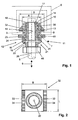
- a tying device 11 for a threaded rod 5 on a mounting rail 6 is shown.
- the mounting rail 6 has an extending in the longitudinal extent of the mounting rail 6 mounting opening 7, which is bounded by arranged at a distance A to each other edges 8.
- the tying device 11 comprises a rear engagement part 32 for partially engaging behind the mounting opening 7 limiting edges 8 and an adjusting device 12 for the threaded rod 5.
- the adjusting device 12 has a rotatably mounted in the rear engagement part 32 sleeve member 13 with an internal thread 14 for the threaded rod 5 and at one first end portion 17 a projecting radially from the sleeve member 13 projection 15 for engaging behind the rear grip part 32.
- a non-rotatably connected to the sleeve member 13 adjusting member 21 is provided, which has a rear grip part 32 facing stop 23.
- the adjusting element 21 has on its outer side a hexagonal formation as a rotary handle 22 for a Verspannwerkmaschine.
- the sleeve member 13 is limited axially slidably mounted to the adjustment member 21.
- connecting means 24 in the form of transversely to the longitudinal axis 26 of the tether 11 extending pins between the adjusting member 21 and the sleeve member 13 are provided.
- the first end portion 17 opposite end portion 19 of the sleeve member 13 is a radially projecting from the sleeve member 13 holding portion 16 for the connection of the sleeve member 13 and the adjusting member 21 is provided.
- the holding portion 16 of the sleeve member 13 also forms an axial stop for the axially to the sleeve member 13 displaceable rear grip part 32.
- the tethering device 11 between the rear engagement part 32 and the stop 23 of the adjusting element 21 comprises a stop element 41 which can be brought into contact with the outside of the mounting rail 6.
- a spring element 36 for spring engagement of the rear grip part 32 in the direction of the stop 23 of the adjusting element 21 is provided between the projection 15 at the free end portion 17 of the sleeve member 13 and the rear engagement part 32.
- the projection 15 is a ring element, which is connected via connecting means 18 with the sleeve member 13.
- the rear grip part 32 advantageously has a length L, which is smaller than the distance A of the mounting opening 7 of the mounting rail 6 bounding edges 8 to each other, and a width B, which is greater than the distance A of the edges 8 of the mounting hole 7 to each other.
- the rear grip part 32 is provided at two, mutually opposite side edges 33, which come in the engaging state of the rear grip part 32 with the mounting rail 6 into abutment, with a profiling 34 which is formed as a toothing.
- the rear engagement part 32 of the tethering device 11 which may be screwed to the mounting bar 6 on the threaded rod 5 before the arrangement, inserted at the desired location in the mounting rail 6 and the entire Tying device 11 is rotated about its longitudinal axis 26 by 90 °, so that the side edges 33 of the rear grip part 32 engage behind the edges 8 of the mounting hole 7.
- the tethering device 11 with the threaded rod and pipe clamp is self-lockingly displaceable along the mounting opening 7. Now the line to be fastened (not shown here) is placed in the pipe clamp.
- sleeve member 13 By turning the adjusting element 21 rotatably mounted in the rear gripping member 32 sleeve member 13 is rotated, wherein the over the male thread of the threaded rod 5 in engagement female thread 14 of the sleeve member 13, the threaded rod 5 according to the direction of rotation of the adjusting member 21 along the longitudinal axis 26 of the tether 11 in the direction of the double arrow 9 to the mounting rail 6 toward or away from it.
- the position of the pipe arranged in the pipe clamp is set perpendicular to the longitudinal direction of the mounting rail 6. Since the threaded rod 5 does not rotate during adjustment, the object fixed on the threaded rod 5, such as a line inserted in a pipe clamp, may remain on the threaded rod 5 during the adjustment process.
- the adjusting device 52 comprises an adjusting element 61 with a receptacle 65, which has coupling surfaces 66 for rotational drive of the sleeve element 53 and for detachable coupling with the sleeve element 53.
- the sleeve member 53 is provided with a portion 56 having correspondingly formed counter-coupling surfaces 57.
- the adjusting member 61 is provided with an internally threaded portion 67, whereby the adjusting member 61 can be screwed onto the threaded rod 5.
- the adjusting element has at its stop a releasable snap-on device which engages in a corresponding counter-device, such as a groove, on the sleeve element.
Claims (7)
- Dispositif d'attache pour une tige filetée (5) sur un rail de montage (6), lequel rail comporte une ouverture de montage (7) délimitée par des rebords (8), muni d'une partie de prise arrière (32) pour réaliser, dans certaines zones, une prise arrière des rebords (8) délimitant l'ouverture de montage (7), et d'un dispositif d'ajustement (12 ; 52) pour la tige filetée (5), dans lequel
le dispositif d'ajustement (12 ; 52) comporte un élément de douille (13 ; 53) monté de manière rotative dans la partie de prise arrière (32), muni d'un filetage intérieur (14) pour la tige filetée (5) ainsi qu'une saillie (15) faisant radialement saillie à partir de l'élément de douille (13 ; 53) sur une première zone d'extrémité (17), pour la prise arrière de la partie de prise arrière (32),
et dans lequel est prévu un élément de réglage (21 ; 61) relié à l'élément de douille (13 ; 53) de manière bloquée en rotation, l'élément de réglage comportant une butée (23) dirigée vers la partie de prise arrière (32), caractérisé en ce que
un élément de ressort (36) est prévu pour solliciter élastiquement la partie de prise arrière (32) en direction de la butée (23) de l'élément de réglage (21) entre la saillie (15) sur la première zone d'extrémité (17) de l'élément de douille (13) et la partie de prise arrière (32). - Dispositif d'attache selon la revendication 1, caractérisé en ce que l'élément de douille (13 ; 53) est monté pour pouvoir être déplacé axialement de manière limitée par rapport à l'élément de réglage (21 ; 61).
- Dispositif d'attache selon la revendication 1 ou 2, caractérisé en ce que des moyens de liaison (24) sont prévus entre l'élément de réglage (21) et l'élément de douille (13) pour un entraînement en rotation de l'élément de douille (13).
- Dispositif d'attache selon la revendication 1 ou 2, caractérisé en ce que l'élément de réglage (61) comporte des surfaces de couplage (66) pour un entraînement en rotation de l'élément de douille (53) pour un couplage amovible avec l'élément de douille (53).
- Dispositif d'attache selon l'une quelconque des revendications 1 à 4, caractérisé en ce qu'un élément de butée (41) est prévu entre la partie de prise arrière (32) et la butée (23) de l'élément de réglage (21).
- Dispositif d'attache selon l'une quelconque des revendications 1 à 5, caractérisé en ce qu'une partie de retenue (16) faisant radialement saillie à partir de l'élément de douille (13) est prévue sur une seconde zone d'extrémité (19) de l'élément de douille (13) en face de la première zone d'extrémité (17), pour le raccordement de l'élément de douille (13) et de l'élément de réglage (21), dans lequel la partie de retenue (16) de l'élément de douille (13) forme une butée axiale pour la partie de prise arrière (32) axialement mobile par rapport à l'élément de douille (13).
- Dispositif d'attache selon l'une quelconque des revendications précédentes, caractérisé en ce que la saillie (15) est formée par un élément annulaire relié à l'élément de douille (13).
Applications Claiming Priority (1)
| Application Number | Priority Date | Filing Date | Title |
|---|---|---|---|
| DE102007000388A DE102007000388A1 (de) | 2007-07-18 | 2007-07-18 | Anbindevorrichtung |
Publications (3)
| Publication Number | Publication Date |
|---|---|
| EP2017484A2 EP2017484A2 (fr) | 2009-01-21 |
| EP2017484A3 EP2017484A3 (fr) | 2010-03-17 |
| EP2017484B1 true EP2017484B1 (fr) | 2011-12-21 |
Family
ID=39930641
Family Applications (1)
| Application Number | Title | Priority Date | Filing Date |
|---|---|---|---|
| EP08104110A Active EP2017484B1 (fr) | 2007-07-18 | 2008-05-27 | Dispositif d'attache |
Country Status (4)
| Country | Link |
|---|---|
| EP (1) | EP2017484B1 (fr) |
| AT (1) | ATE538319T1 (fr) |
| DE (1) | DE102007000388A1 (fr) |
| ES (1) | ES2376373T3 (fr) |
Families Citing this family (1)
| Publication number | Priority date | Publication date | Assignee | Title |
|---|---|---|---|---|
| DE102009000736A1 (de) * | 2009-02-10 | 2010-08-19 | Hilti Aktiengesellschaft | Befestigungsvorrichtung zur Anordnung eines Stangenelementes an einer Montageschiene |
Family Cites Families (3)
| Publication number | Priority date | Publication date | Assignee | Title |
|---|---|---|---|---|
| DE3823000C2 (de) | 1988-07-07 | 1996-02-29 | Wolfgang Halpaus | Befestigungselement |
| DE59814202D1 (de) | 1997-09-26 | 2008-05-15 | Wolfgang Halpaus | Befestigungselement |
| DE29820923U1 (de) | 1997-12-01 | 1999-02-25 | Halpaus Wolfgang | Befestigungselement |
-
2007
- 2007-07-18 DE DE102007000388A patent/DE102007000388A1/de not_active Withdrawn
-
2008
- 2008-05-27 AT AT08104110T patent/ATE538319T1/de active
- 2008-05-27 ES ES08104110T patent/ES2376373T3/es active Active
- 2008-05-27 EP EP08104110A patent/EP2017484B1/fr active Active
Also Published As
| Publication number | Publication date |
|---|---|
| EP2017484A3 (fr) | 2010-03-17 |
| ES2376373T3 (es) | 2012-03-13 |
| ATE538319T1 (de) | 2012-01-15 |
| DE102007000388A1 (de) | 2009-01-22 |
| EP2017484A2 (fr) | 2009-01-21 |
Similar Documents
| Publication | Publication Date | Title |
|---|---|---|
| DE1900078C3 (de) | Schnellbefestigungsvorrichtung | |
| EP2218924B1 (fr) | Dispositif de fixation destiné à l'agencement sur un rail de montage | |
| EP1426636B1 (fr) | Ecrou de support rapide | |
| EP2500587A1 (fr) | Dispositif de fixation destiné à l'agencement sur un rail de montage | |
| EP3374648B1 (fr) | Ensemble de liaison pour rails de montage | |
| DE102013113735A1 (de) | Befestiger, Befestigungssystem und Verfahren zur Montage eines Befestigers an einer Montageschiene | |
| EP3673181A1 (fr) | Système de vissage rapide, en particulier pour l'assemblage de modules en plusieurs parties | |
| WO2016012081A1 (fr) | Dispositif de fixation d'un rail de montage | |
| DE102007013438B4 (de) | Blumenkastenhalterung mit einer Klemmvorrichtung | |
| DE19946890C2 (de) | Halteelement zur unverlierbaren Halterung von Kopfschrauben | |
| DE3823000C2 (de) | Befestigungselement | |
| EP2228552A1 (fr) | Dispositif de fixation destiné à l'agencement sur un rail de montage | |
| EP2017485B1 (fr) | Dispositif d'attache | |
| EP2017484B1 (fr) | Dispositif d'attache | |
| DE202007013500U1 (de) | Verbinder sowie Anordnung von zwei mit einem solchen Verbinder verbundenen Gegenständen | |
| DE102011115627B4 (de) | Spreizvorrichtung | |
| DE102014217781A1 (de) | Vorrichtung zum Befestigen eines Verkleidungselements | |
| EP2221490B1 (fr) | Elément de fixation en une pièce destiné à l'agencement d'un élément de tiges sur un rail de montage | |
| WO2017021182A1 (fr) | Colonne de direction pour véhicule automobile | |
| DE102005037200A1 (de) | Rohrschelle | |
| EP3144544B1 (fr) | Systeme d'articulation destine au positionnement de composants | |
| DE19958104C2 (de) | Vorrichtung zum Verbinden zweier Teile | |
| DE202021104753U1 (de) | Schnellspannmutter zum Gegeneinander-Verspannen von Schalungswänden einer Betonwandschalung | |
| EP2309136A2 (fr) | Elément de raccordement de rails | |
| DE102015111076A1 (de) | Befestiger für eine Montageschiene |
Legal Events
| Date | Code | Title | Description |
|---|---|---|---|
| PUAI | Public reference made under article 153(3) epc to a published international application that has entered the european phase |
Free format text: ORIGINAL CODE: 0009012 |
|
| AK | Designated contracting states |
Kind code of ref document: A2 Designated state(s): AT BE BG CH CY CZ DE DK EE ES FI FR GB GR HR HU IE IS IT LI LT LU LV MC MT NL NO PL PT RO SE SI SK TR |
|
| AX | Request for extension of the european patent |
Extension state: AL BA MK RS |
|
| PUAL | Search report despatched |
Free format text: ORIGINAL CODE: 0009013 |
|
| AK | Designated contracting states |
Kind code of ref document: A3 Designated state(s): AT BE BG CH CY CZ DE DK EE ES FI FR GB GR HR HU IE IS IT LI LT LU LV MC MT NL NO PL PT RO SE SI SK TR |
|
| AX | Request for extension of the european patent |
Extension state: AL BA MK RS |
|
| 17P | Request for examination filed |
Effective date: 20100917 |
|
| 17Q | First examination report despatched |
Effective date: 20101012 |
|
| AKX | Designation fees paid |
Designated state(s): AT BE BG CH CY CZ DE DK EE ES FI FR GB GR HR HU IE IS IT LI LT LU LV MC MT NL NO PL PT RO SE SI SK TR |
|
| GRAP | Despatch of communication of intention to grant a patent |
Free format text: ORIGINAL CODE: EPIDOSNIGR1 |
|
| GRAS | Grant fee paid |
Free format text: ORIGINAL CODE: EPIDOSNIGR3 |
|
| GRAA | (expected) grant |
Free format text: ORIGINAL CODE: 0009210 |
|
| AK | Designated contracting states |
Kind code of ref document: B1 Designated state(s): AT BE BG CH CY CZ DE DK EE ES FI FR GB GR HR HU IE IS IT LI LT LU LV MC MT NL NO PL PT RO SE SI SK TR |
|
| REG | Reference to a national code |
Ref country code: GB Ref legal event code: FG4D Free format text: NOT ENGLISH |
|
| REG | Reference to a national code |
Ref country code: CH Ref legal event code: EP |
|
| REG | Reference to a national code |
Ref country code: AT Ref legal event code: REF Ref document number: 538319 Country of ref document: AT Kind code of ref document: T Effective date: 20120115 |
|
| REG | Reference to a national code |
Ref country code: IE Ref legal event code: FG4D |
|
| REG | Reference to a national code |
Ref country code: DE Ref legal event code: R096 Ref document number: 502008005916 Country of ref document: DE Effective date: 20120308 |
|
| REG | Reference to a national code |
Ref country code: ES Ref legal event code: FG2A Ref document number: 2376373 Country of ref document: ES Kind code of ref document: T3 Effective date: 20120313 |
|
| REG | Reference to a national code |
Ref country code: NL Ref legal event code: VDEP Effective date: 20111221 |
|
| PG25 | Lapsed in a contracting state [announced via postgrant information from national office to epo] |
Ref country code: LT Free format text: LAPSE BECAUSE OF FAILURE TO SUBMIT A TRANSLATION OF THE DESCRIPTION OR TO PAY THE FEE WITHIN THE PRESCRIBED TIME-LIMIT Effective date: 20111221 Ref country code: NO Free format text: LAPSE BECAUSE OF FAILURE TO SUBMIT A TRANSLATION OF THE DESCRIPTION OR TO PAY THE FEE WITHIN THE PRESCRIBED TIME-LIMIT Effective date: 20120321 |
|
| LTIE | Lt: invalidation of european patent or patent extension |
Effective date: 20111221 |
|
| PG25 | Lapsed in a contracting state [announced via postgrant information from national office to epo] |
Ref country code: GR Free format text: LAPSE BECAUSE OF FAILURE TO SUBMIT A TRANSLATION OF THE DESCRIPTION OR TO PAY THE FEE WITHIN THE PRESCRIBED TIME-LIMIT Effective date: 20120322 Ref country code: HR Free format text: LAPSE BECAUSE OF FAILURE TO SUBMIT A TRANSLATION OF THE DESCRIPTION OR TO PAY THE FEE WITHIN THE PRESCRIBED TIME-LIMIT Effective date: 20111221 Ref country code: SE Free format text: LAPSE BECAUSE OF FAILURE TO SUBMIT A TRANSLATION OF THE DESCRIPTION OR TO PAY THE FEE WITHIN THE PRESCRIBED TIME-LIMIT Effective date: 20111221 Ref country code: NL Free format text: LAPSE BECAUSE OF FAILURE TO SUBMIT A TRANSLATION OF THE DESCRIPTION OR TO PAY THE FEE WITHIN THE PRESCRIBED TIME-LIMIT Effective date: 20111221 Ref country code: SI Free format text: LAPSE BECAUSE OF FAILURE TO SUBMIT A TRANSLATION OF THE DESCRIPTION OR TO PAY THE FEE WITHIN THE PRESCRIBED TIME-LIMIT Effective date: 20111221 Ref country code: LV Free format text: LAPSE BECAUSE OF FAILURE TO SUBMIT A TRANSLATION OF THE DESCRIPTION OR TO PAY THE FEE WITHIN THE PRESCRIBED TIME-LIMIT Effective date: 20111221 |
|
| PG25 | Lapsed in a contracting state [announced via postgrant information from national office to epo] |
Ref country code: CY Free format text: LAPSE BECAUSE OF FAILURE TO SUBMIT A TRANSLATION OF THE DESCRIPTION OR TO PAY THE FEE WITHIN THE PRESCRIBED TIME-LIMIT Effective date: 20111221 |
|
| REG | Reference to a national code |
Ref country code: IE Ref legal event code: FD4D |
|
| PG25 | Lapsed in a contracting state [announced via postgrant information from national office to epo] |
Ref country code: CZ Free format text: LAPSE BECAUSE OF FAILURE TO SUBMIT A TRANSLATION OF THE DESCRIPTION OR TO PAY THE FEE WITHIN THE PRESCRIBED TIME-LIMIT Effective date: 20111221 Ref country code: BG Free format text: LAPSE BECAUSE OF FAILURE TO SUBMIT A TRANSLATION OF THE DESCRIPTION OR TO PAY THE FEE WITHIN THE PRESCRIBED TIME-LIMIT Effective date: 20120321 Ref country code: IS Free format text: LAPSE BECAUSE OF FAILURE TO SUBMIT A TRANSLATION OF THE DESCRIPTION OR TO PAY THE FEE WITHIN THE PRESCRIBED TIME-LIMIT Effective date: 20120421 Ref country code: EE Free format text: LAPSE BECAUSE OF FAILURE TO SUBMIT A TRANSLATION OF THE DESCRIPTION OR TO PAY THE FEE WITHIN THE PRESCRIBED TIME-LIMIT Effective date: 20111221 Ref country code: SK Free format text: LAPSE BECAUSE OF FAILURE TO SUBMIT A TRANSLATION OF THE DESCRIPTION OR TO PAY THE FEE WITHIN THE PRESCRIBED TIME-LIMIT Effective date: 20111221 Ref country code: IE Free format text: LAPSE BECAUSE OF FAILURE TO SUBMIT A TRANSLATION OF THE DESCRIPTION OR TO PAY THE FEE WITHIN THE PRESCRIBED TIME-LIMIT Effective date: 20111221 |
|
| PG25 | Lapsed in a contracting state [announced via postgrant information from national office to epo] |
Ref country code: PL Free format text: LAPSE BECAUSE OF FAILURE TO SUBMIT A TRANSLATION OF THE DESCRIPTION OR TO PAY THE FEE WITHIN THE PRESCRIBED TIME-LIMIT Effective date: 20111221 Ref country code: PT Free format text: LAPSE BECAUSE OF FAILURE TO SUBMIT A TRANSLATION OF THE DESCRIPTION OR TO PAY THE FEE WITHIN THE PRESCRIBED TIME-LIMIT Effective date: 20120423 Ref country code: RO Free format text: LAPSE BECAUSE OF FAILURE TO SUBMIT A TRANSLATION OF THE DESCRIPTION OR TO PAY THE FEE WITHIN THE PRESCRIBED TIME-LIMIT Effective date: 20111221 |
|
| PLBE | No opposition filed within time limit |
Free format text: ORIGINAL CODE: 0009261 |
|
| STAA | Information on the status of an ep patent application or granted ep patent |
Free format text: STATUS: NO OPPOSITION FILED WITHIN TIME LIMIT |
|
| PG25 | Lapsed in a contracting state [announced via postgrant information from national office to epo] |
Ref country code: DK Free format text: LAPSE BECAUSE OF FAILURE TO SUBMIT A TRANSLATION OF THE DESCRIPTION OR TO PAY THE FEE WITHIN THE PRESCRIBED TIME-LIMIT Effective date: 20111221 |
|
| 26N | No opposition filed |
Effective date: 20120924 |
|
| BERE | Be: lapsed |
Owner name: HILTI AKTIENGESELLSCHAFT Effective date: 20120531 |
|
| PG25 | Lapsed in a contracting state [announced via postgrant information from national office to epo] |
Ref country code: MC Free format text: LAPSE BECAUSE OF NON-PAYMENT OF DUE FEES Effective date: 20120531 |
|
| REG | Reference to a national code |
Ref country code: DE Ref legal event code: R097 Ref document number: 502008005916 Country of ref document: DE Effective date: 20120924 |
|
| PG25 | Lapsed in a contracting state [announced via postgrant information from national office to epo] |
Ref country code: BE Free format text: LAPSE BECAUSE OF NON-PAYMENT OF DUE FEES Effective date: 20120531 |
|
| PG25 | Lapsed in a contracting state [announced via postgrant information from national office to epo] |
Ref country code: FI Free format text: LAPSE BECAUSE OF FAILURE TO SUBMIT A TRANSLATION OF THE DESCRIPTION OR TO PAY THE FEE WITHIN THE PRESCRIBED TIME-LIMIT Effective date: 20111221 |
|
| PG25 | Lapsed in a contracting state [announced via postgrant information from national office to epo] |
Ref country code: MT Free format text: LAPSE BECAUSE OF FAILURE TO SUBMIT A TRANSLATION OF THE DESCRIPTION OR TO PAY THE FEE WITHIN THE PRESCRIBED TIME-LIMIT Effective date: 20111221 |
|
| PG25 | Lapsed in a contracting state [announced via postgrant information from national office to epo] |
Ref country code: LU Free format text: LAPSE BECAUSE OF NON-PAYMENT OF DUE FEES Effective date: 20120527 |
|
| PG25 | Lapsed in a contracting state [announced via postgrant information from national office to epo] |
Ref country code: HU Free format text: LAPSE BECAUSE OF FAILURE TO SUBMIT A TRANSLATION OF THE DESCRIPTION OR TO PAY THE FEE WITHIN THE PRESCRIBED TIME-LIMIT Effective date: 20080527 |
|
| PGFP | Annual fee paid to national office [announced via postgrant information from national office to epo] |
Ref country code: GB Payment date: 20140521 Year of fee payment: 7 |
|
| PGFP | Annual fee paid to national office [announced via postgrant information from national office to epo] |
Ref country code: FR Payment date: 20140509 Year of fee payment: 7 Ref country code: TR Payment date: 20140429 Year of fee payment: 7 Ref country code: AT Payment date: 20140428 Year of fee payment: 7 Ref country code: IT Payment date: 20140522 Year of fee payment: 7 Ref country code: ES Payment date: 20140411 Year of fee payment: 7 Ref country code: CH Payment date: 20140513 Year of fee payment: 7 |
|
| REG | Reference to a national code |
Ref country code: CH Ref legal event code: PL |
|
| REG | Reference to a national code |
Ref country code: AT Ref legal event code: MM01 Ref document number: 538319 Country of ref document: AT Kind code of ref document: T Effective date: 20150527 |
|
| GBPC | Gb: european patent ceased through non-payment of renewal fee |
Effective date: 20150527 |
|
| PG25 | Lapsed in a contracting state [announced via postgrant information from national office to epo] |
Ref country code: IT Free format text: LAPSE BECAUSE OF NON-PAYMENT OF DUE FEES Effective date: 20150527 Ref country code: CH Free format text: LAPSE BECAUSE OF NON-PAYMENT OF DUE FEES Effective date: 20150531 Ref country code: LI Free format text: LAPSE BECAUSE OF NON-PAYMENT OF DUE FEES Effective date: 20150531 |
|
| REG | Reference to a national code |
Ref country code: FR Ref legal event code: ST Effective date: 20160129 |
|
| PG25 | Lapsed in a contracting state [announced via postgrant information from national office to epo] |
Ref country code: AT Free format text: LAPSE BECAUSE OF NON-PAYMENT OF DUE FEES Effective date: 20150527 |
|
| PG25 | Lapsed in a contracting state [announced via postgrant information from national office to epo] |
Ref country code: GB Free format text: LAPSE BECAUSE OF NON-PAYMENT OF DUE FEES Effective date: 20150527 |
|
| PG25 | Lapsed in a contracting state [announced via postgrant information from national office to epo] |
Ref country code: FR Free format text: LAPSE BECAUSE OF NON-PAYMENT OF DUE FEES Effective date: 20150601 |
|
| REG | Reference to a national code |
Ref country code: ES Ref legal event code: FD2A Effective date: 20160627 |
|
| PG25 | Lapsed in a contracting state [announced via postgrant information from national office to epo] |
Ref country code: ES Free format text: LAPSE BECAUSE OF NON-PAYMENT OF DUE FEES Effective date: 20150528 |
|
| PG25 | Lapsed in a contracting state [announced via postgrant information from national office to epo] |
Ref country code: TR Free format text: LAPSE BECAUSE OF NON-PAYMENT OF DUE FEES Effective date: 20150527 |
|
| PGFP | Annual fee paid to national office [announced via postgrant information from national office to epo] |
Ref country code: DE Payment date: 20230519 Year of fee payment: 16 |