EP2017484B1 - Anbindevorrichtung - Google Patents
Anbindevorrichtung Download PDFInfo
- Publication number
- EP2017484B1 EP2017484B1 EP08104110A EP08104110A EP2017484B1 EP 2017484 B1 EP2017484 B1 EP 2017484B1 EP 08104110 A EP08104110 A EP 08104110A EP 08104110 A EP08104110 A EP 08104110A EP 2017484 B1 EP2017484 B1 EP 2017484B1
- Authority
- EP
- European Patent Office
- Prior art keywords
- grip part
- rear grip
- sleeve element
- sleeve
- threaded rod
- Prior art date
- Legal status (The legal status is an assumption and is not a legal conclusion. Google has not performed a legal analysis and makes no representation as to the accuracy of the status listed.)
- Not-in-force
Links
Images

Classifications
-
- F—MECHANICAL ENGINEERING; LIGHTING; HEATING; WEAPONS; BLASTING
- F16—ENGINEERING ELEMENTS AND UNITS; GENERAL MEASURES FOR PRODUCING AND MAINTAINING EFFECTIVE FUNCTIONING OF MACHINES OR INSTALLATIONS; THERMAL INSULATION IN GENERAL
- F16B—DEVICES FOR FASTENING OR SECURING CONSTRUCTIONAL ELEMENTS OR MACHINE PARTS TOGETHER, e.g. NAILS, BOLTS, CIRCLIPS, CLAMPS, CLIPS OR WEDGES; JOINTS OR JOINTING
- F16B37/00—Nuts or like thread-engaging members
- F16B37/04—Devices for fastening nuts to surfaces, e.g. sheets, plates
- F16B37/045—Devices for fastening nuts to surfaces, e.g. sheets, plates specially adapted for fastening in channels, e.g. sliding bolts, channel nuts
Definitions
- the invention relates to a tether for a threaded rod on a mounting rail, which has a limited opening edges, with a rear engagement portion for engaging behind the mounting opening limiting edges and an adjusting device for the threaded rod, wherein the adjusting device rotatably mounted in the rear grip member sleeve member having a Internal thread for the threaded rod and at a first end portion has a radially projecting from the sleeve member projection for engaging behind the rear grip part, and wherein a non-rotatably connected to the sleeve member adjusting member is provided which has a rear grip part facing stop.
- a pipe clamp via a threaded rod at a distance from the mounting rail can be fixed.
- Such mounting rails have at least one in the longitudinal extent of the mounting rail extending, limited by spaced edges mounting opening.
- a tying device for a threaded rod on a mounting rail which has a rear engagement portion for engaging behind the mounting opening limiting edges and an adjusting device for the threaded rod.
- the rear grip part has a length which is smaller than the distance of the mounting opening of the mounting rail limiting edges to each other, and a width which is greater than the distance between the edges of the mounting opening to each other.
- the rear engagement part can be inserted through the mounting opening in the mounting rail and be brought by rotation of the tether about the longitudinal axis of 90 ° in a position engaging behind the mounting hole. In the unstressed position of the tether this is displaceable for positioning of the tether along the mounting rail.
- the adjusting device of the tether according to DE 38 23 000 A1 has a rotatably mounted in the rear engagement part sleeve member with an internal thread for the threaded rod and an external thread. At a first end portion of the sleeve member, a radially projecting from this protrusion for engaging behind the rear grip part is provided. After insertion of the rear grip part in the mounting opening a clamping nut is screwed onto the external thread of the sleeve member until the tether is braced with the mounting rail. In this case, areas of the mounting opening bounding edges between the rear grip part and the nut are clamped. Subsequently, the threaded rod to be fixed to the tying device is screwed into the internal thread and fixed according to the desired orientation with respect to the mounting rail with a locking nut arranged on the threaded rod in this position.
- connection After inserting the lines in the clamps, it is often necessary, for. B. due to unevenness of the ground or to ensure a gradient of the line to be fixed, the connection subsequently adjust in height and thus align the lines each at the desired distance to the ground.
- a disadvantage of the known solution according to the DE 38 23 000 A1 is that the mounting of the tether to the mounting rail is complex.
- the EP 0905425 A2 relates to a fastener for fixing any components to an undercut mounting opening, with a usable in this support member which is rotatable in the interior of the mounting hole and thereby engages behind the mounting opening bounding retaining projections, with a separate counter-holding plate, which is externally supported on the retaining projections, and with an elastic An element, wherein the elastic member connects the support member and the counter-holding plate, and wherein a connecting member is rotatably secured to the support member and length-adjustable in its longitudinal direction when the fastener is fixed to the mounting hole.
- a conical pressure spring can be provided, which acts on the counter-holding plate.
- a similar fastener with conical spring goes out of the DE 298 20 923 U1 out.
- the object of the invention is to provide a tying device for an adjustable threaded rod on a mounting rail, which allows easy mounting of the tether on the mounting rail.
- a non-rotatably connected to the sleeve member adjusting member which has a rear grip part facing stop.
- threaded rod By turning the adjusting element arranged in the internal thread of the sleeve member threaded rod is adjusted in height or at a distance from the mounting rail, without causing the threaded rod rotates about its longitudinal axis or the longitudinal axis of the tether.
- the threaded rod is moved in the adjustment only in the direction of the longitudinal axis to the desired extent.
- a locking nut is arranged on the threaded rod and brought into abutment with the adjusting element.
- the tether is braced with the mounting rail and areas of the mounting opening bounding edges between the rear grip part and the stop of the adjustment clamped.
- the rear grip part has a sufficiently stable configuration which prevents bending of the rear grip part under the load attached to the threaded rod.
- the rear grip part is made of metal, for example of metal casting.
- the edges of the mounting rail are also provided with a profiling, wherein advantageously the profiling is formed on the rear grip complementary to this profiling.
- the profiling is advantageous in each case a toothing.
- the tethering device is advantageously provided preassembled to the user, wherein the individual parts of the tethering device are further advantageously connected to one another in a captive manner.
- the sleeve member is limited axially slidably mounted to the adjustment, which facilitates the mounting of the tether to the mounting rail.
- a sufficiently large distance between the rear engagement part and the stop of the adjusting element can be provided, which can easily be reduced during bracing of the tethering device to the required distance for clamping the edges engaging behind the mounting opening.
- a connecting means between the adjusting element and the sleeve member is provided for the rotational drive of the sleeve member.
- the connecting means comprises, for example, pins, which are arranged in corresponding, formed on the sleeve member and the adjusting receptacles and ensure the rotationally fixed connection between the two parts.
- the adjusting element for the rotational drive of the sleeve element has coupling surfaces for detachable coupling with the Sleeve element on.
- the adjusting element has, for example, a receptacle provided with coupling surfaces, which can be brought together with a section of the sleeve element which is essentially complementary thereto.
- the coupling receptacle is a hexagonal receptacle, as used for example for Allen tools.
- the section on the sleeve element is provided with mating coupling surfaces.
- a stop element between the rear engagement part and the stop of the adjustment is provided, which comes into contact with the outside of the mounting rail.
- the adjustment is advantageously on the outside of the stop and is rotatable to this.
- a spring element is provided for spring loading of the rear engagement part in the direction of the stop of the adjustment element between the projection on the first end region of the sleeve element and the rear engagement part.
- the spring element is a compression spring and, for example, designed as a spiral spring.
- the spring element biases the rear engagement part in the direction of the adjustment element, so that after the arrangement of the attachment device to the mounting rail it is held in a self-locking manner on the mounting rail. Due to the self-locking displaceability of the tether in the mounting hole a simple installation of the tethering device is ensured even with vertically aligned mounting rails.
- the projection is formed by a ring element connected to the sleeve element.
- the ring element is advantageously connected via connecting means such as retaining pins with the sleeve member, wherein the compound is particularly advantageous rotatably formed.
- the cylindrical end of the sleeve element is widened radially outwardly, for example by crimping, whereby the radially radially extending edge created thereby forms the ring element of the sleeve element forming the projection.
- a tying device 11 for a threaded rod 5 on a mounting rail 6 is shown.
- the mounting rail 6 has an extending in the longitudinal extent of the mounting rail 6 mounting opening 7, which is bounded by arranged at a distance A to each other edges 8.
- the tying device 11 comprises a rear engagement part 32 for partially engaging behind the mounting opening 7 limiting edges 8 and an adjusting device 12 for the threaded rod 5.
- the adjusting device 12 has a rotatably mounted in the rear engagement part 32 sleeve member 13 with an internal thread 14 for the threaded rod 5 and at one first end portion 17 a projecting radially from the sleeve member 13 projection 15 for engaging behind the rear grip part 32.
- a non-rotatably connected to the sleeve member 13 adjusting member 21 is provided, which has a rear grip part 32 facing stop 23.
- the adjusting element 21 has on its outer side a hexagonal formation as a rotary handle 22 for a Verspannwerkmaschine.
- the sleeve member 13 is limited axially slidably mounted to the adjustment member 21.
- connecting means 24 in the form of transversely to the longitudinal axis 26 of the tether 11 extending pins between the adjusting member 21 and the sleeve member 13 are provided.
- the first end portion 17 opposite end portion 19 of the sleeve member 13 is a radially projecting from the sleeve member 13 holding portion 16 for the connection of the sleeve member 13 and the adjusting member 21 is provided.
- the holding portion 16 of the sleeve member 13 also forms an axial stop for the axially to the sleeve member 13 displaceable rear grip part 32.
- the tethering device 11 between the rear engagement part 32 and the stop 23 of the adjusting element 21 comprises a stop element 41 which can be brought into contact with the outside of the mounting rail 6.
- a spring element 36 for spring engagement of the rear grip part 32 in the direction of the stop 23 of the adjusting element 21 is provided between the projection 15 at the free end portion 17 of the sleeve member 13 and the rear engagement part 32.
- the projection 15 is a ring element, which is connected via connecting means 18 with the sleeve member 13.
- the rear grip part 32 advantageously has a length L, which is smaller than the distance A of the mounting opening 7 of the mounting rail 6 bounding edges 8 to each other, and a width B, which is greater than the distance A of the edges 8 of the mounting hole 7 to each other.
- the rear grip part 32 is provided at two, mutually opposite side edges 33, which come in the engaging state of the rear grip part 32 with the mounting rail 6 into abutment, with a profiling 34 which is formed as a toothing.
- the rear engagement part 32 of the tethering device 11 which may be screwed to the mounting bar 6 on the threaded rod 5 before the arrangement, inserted at the desired location in the mounting rail 6 and the entire Tying device 11 is rotated about its longitudinal axis 26 by 90 °, so that the side edges 33 of the rear grip part 32 engage behind the edges 8 of the mounting hole 7.
- the tethering device 11 with the threaded rod and pipe clamp is self-lockingly displaceable along the mounting opening 7. Now the line to be fastened (not shown here) is placed in the pipe clamp.
- sleeve member 13 By turning the adjusting element 21 rotatably mounted in the rear gripping member 32 sleeve member 13 is rotated, wherein the over the male thread of the threaded rod 5 in engagement female thread 14 of the sleeve member 13, the threaded rod 5 according to the direction of rotation of the adjusting member 21 along the longitudinal axis 26 of the tether 11 in the direction of the double arrow 9 to the mounting rail 6 toward or away from it.
- the position of the pipe arranged in the pipe clamp is set perpendicular to the longitudinal direction of the mounting rail 6. Since the threaded rod 5 does not rotate during adjustment, the object fixed on the threaded rod 5, such as a line inserted in a pipe clamp, may remain on the threaded rod 5 during the adjustment process.
- the adjusting device 52 comprises an adjusting element 61 with a receptacle 65, which has coupling surfaces 66 for rotational drive of the sleeve element 53 and for detachable coupling with the sleeve element 53.
- the sleeve member 53 is provided with a portion 56 having correspondingly formed counter-coupling surfaces 57.
- the adjusting member 61 is provided with an internally threaded portion 67, whereby the adjusting member 61 can be screwed onto the threaded rod 5.
- the adjusting element has at its stop a releasable snap-on device which engages in a corresponding counter-device, such as a groove, on the sleeve element.
Landscapes
- Engineering & Computer Science (AREA)
- General Engineering & Computer Science (AREA)
- Mechanical Engineering (AREA)
- Mutual Connection Of Rods And Tubes (AREA)
- Package Frames And Binding Bands (AREA)
- Manufacturing Of Electrical Connectors (AREA)
- Hand Tools For Fitting Together And Separating, Or Other Hand Tools (AREA)
- Agricultural Machines (AREA)
- Clamps And Clips (AREA)
Description
- Die Erfindung betrifft eine Anbindevorrichtung für eine Gewindestange an einer Montageschiene, die eine von Rändern begrenzte Montageöffnung aufweist, mit einem Hintergreifteil zum bereichsweisen Hintergreifen der die Montageöffnung begrenzenden Ränder und einer Justiereinrichtung für die Gewindestange, wobei die Justiereinrichtung ein drehbar in dem Hintergreifteil gelagertes Hülsenelement mit einem Innengewinde für die Gewindestange sowie an einem ersten Endbereich einen radial von dem Hülsenelement abragenden Vorsprung zum Hintergreifen des Hintergreifteils aufweist, und wobei ein drehfest mit dem Hülsenelement verbundenes Einstellelement vorgesehen ist, das einen dem Hintergreifteil zugewandten Anschlag aufweist.
- Für eine flexible Installation von Leitungen, wie Rohren, Lüftungskanälen, Elektrokabeltrassen und dergleichen, im Bereich der Haustechnik oder der Industrie werden Montageschienen eingesetzt, an denen mittels einer Anbindevorrichtung z. B. eine Rohrschelle über eine Gewindestange im Abstand zu der Montageschiene festlegbar ist.
- Derartige Montageschienen weisen zumindest eine in Längserstreckung der Montageschiene verlaufende, von zueinander beabstandeten Rändern begrenzte Montageöffnung auf. In der Montageöffnung sind Gewindestangen z. B. mittels Schienenmuttem festlegbar, an denen die Rohrschellen für die Leitungen angeordnet werden.
- Aus der
DE 38 23 000 A1 ist eine Anbindevorrichtung für eine Gewindestange an einer Montageschiene bekannt, die ein Hintergreifteil zum bereichsweisen Hintergreifen der die Montageöffnung begrenzenden Ränder und einer Justiereinrichtung für die Gewindestange aufweist. Das Hintergreifteil weist eine Länge, die kleiner als der Abstand der die Montageöffnung der Montageschiene begrenzenden Ränder zueinander ist, sowie eine Breite auf, die grösser als der Abstand der Ränder der Montageöffnung zueinander ist. Damit kann das Hintergreifteil durch die Montageöffnung in die Montageschiene eingeführt und durch eine Drehung der Anbindevorrichtung um die Längsachse von 90° in eine die Montageöffnung hintergreifende Stellung gebracht werden. In der unverspannten Stellung der Anbindevorrichtung ist diese für eine Positionierung der Anbindevorrichtung entlang der Montageschiene verschiebbar. - Die Justiereinrichtung der Anbindevorrichtung gemäss der
DE 38 23 000 A1 weist ein drehbar in dem Hintergreifteil gelagertes Hülsenelement mit einem Innengewinde für die Gewindestange sowie einem Aussengewinde auf. An einem ersten Endbereich des Hülsenelementes ist ein radial von diesem abragender Vorsprung zum Hintergreifen des Hintergreifteils vorgesehen. Nach dem Einführen des Hintergreifteils in die Montageöffnung wird auf das Aussengewinde des Hülsenelementes eine Spannmutter aufgeschraubt, bis die Anbindevorrichtung mit der Montageschiene verspannt ist. Dabei werden Bereiche der die Montageöffnung begrenzenden Ränder zwischen dem Hintergreifteil und der Mutter eingeklemmt. Anschliessend wird die an der Anbindevorrichtung festzulegende Gewindestange in das Innengewinde eingeschraubt und nach der gewünschten Ausrichtung bezüglich der Montageschiene mit einer auf der Gewindestange angeordneten Sicherungsmutter in dieser Stellung fixiert. - Nach dem Einlegen der Leitungen in die Rohrschellen ist es oftmals erforderlich, z. B. aufgrund von Unebenheiten des Untergrundes oder zur Gewährleistung eines Gefälles der zu fixierenden Leitung, die Anbindung nachträglich in der Höhe zu justieren und somit die Leitungen jeweils im gewünschten Abstand zum Untergrund auszurichten.
- Nachteilig an der bekannten Lösung gemäss der
DE 38 23 000 A1 ist, dass die Montage der Anbindevorrichtung an der Montageschiene aufwändig ist. - Die
EP 0905425 A2 betrifft ein Befestigungselement zum Festlegen beliebiger Bauteile an einer hinterschnittenen Befestigungsöffnung, mit einem in diese einsetzbaren Stützteil, das im Inneren der Befestigungsöffnung verdrehbar ist und dabei die Befestigungsöffnung begrenzenden Haltevorsprünge hintergreift, mit einer separaten Gegenhalteplatte, die aussen an den Haltevorsprüngen abstützt, sowie mit einem elastischen Element, wobei das elastischen Element das Stützteil und die Gegenhalteplatte verbindet und wobei ein Verbindungsteil am Stützteil drehbar zu befestigen ist und in seiner Längsrichtung längenanpassbar ist, wenn das Befestigungselement an der Befestigungsöffnung festgelegt ist. Dabei kann eine Kegeldruckfeder vorgesehen sein, die auf die Gegenhalteplatte wirkt. Ein ähnliches Befestigungselement mit Kegeldruchfeder geht aus derDE 298 20 923 U1 hervor. - Aufgabe der Erfindung ist es, eine Anbindevorrichtung für eine justierbare Gewindestange an einer Montageschiene zu schaffen, die eine einfache Montage der Anbindevorrichtung an der Montageschiene ermöglicht.
- Die Aufgabe ist durch die Merkmale des unabhängigen Anspruchs gelöst. Vorteilhafte Weiterbildungen sind in den Unteransprüchen dargelegt.
- Die Erfindung nach Anspruch 1 ist dadurch gekennzeichnet, dass ein Federelement zur Federbeaufschlagung des Hintergreifteils in Richtung des Anschlages des Einstellelementes zwischen dem Vorsprung am ersten Endbereich des Hülsenelementes und dem Hintergreifteil vorgesehen ist.
- Gemäss der Erfindung ist ein drehfest mit dem Hülsenelement verbundenes Einstellelement vorgesehen, das einen dem Hintergreifteil zugewandten Anschlag aufweist.
- Durch Drehen des Einstellelementes wird eine in dem Innengewinde des Hülsenelementes angeordnete Gewindestange in der Höhe beziehungsweise im Abstand zu der Montageschiene justiert, ohne dass dabei die Gewindestange um ihre Längsachse beziehungsweise die Längsachse der Anbindevorrichtung rotiert. Die Gewindestange wird bei der Justierung nur in Richtung der Längsachse im gewünschten Mass verschoben.
- Anschliessend wird beispielsweise eine Sicherungsmutter auf der Gewindestange angeordnet und mit dem Einstellelement in Anlage gebracht. Dabei wird die Anbindevorrichtung mit der Montageschiene verspannt und Bereiche der die Montageöffnung begrenzenden Ränder zwischen dem Hintergreifteil und dem Anschlag des Einstellelementes eingeklemmt.
- Das Hintergreifteil weist eine ausreichend stabile Ausgestaltung auf, welche ein Verbiegen des Hintergreifteils unter der an der Gewindestange angehängten Last verhindert. Vorteilhaft ist das Hintergreifteil aus Metall gefertigt, beispielsweise aus Metallguss.
- Für eine formschlüssige Fixierung der Anbindevorrichtung an der Montageschiene ist vorteilhaft eine Profilierung an zwei, einander gegenüberliegenden Seitenrändern des Hintergreifteils vorgesehen, die in der hintergreifenden Stellung des Hintergreifteils mit den die Montageöffnung begrenzenden Rändern in Anlage kommen. Vorteilhaft sind die Ränder der Montageschiene ebenfalls mit einer Profilierung versehen, wobei vorteilhaft die Profilierung am Hintergreifteil komplementär zu dieser Profilierung ausgebildet ist. Für einen verbesserten Formschluss zwischen dem Hintergreifteil und der Montageschiene ist die Profilierung vorteilhaft jeweils eine Verzahnung.
- Die Anbindevorrichtung wird dem Anwender vorteilhaft vormontiert zur Verfügung gestellt, wobei die einzelnen Teile der Anbindevorrichtung weiter vorteilhaft unverlierbar miteinander verbunden sind.
- Vorzugsweise ist das Hülsenelement begrenzt axial verschieblich zu dem Einstellelement gelagert, was die Montage der Anbindevorrichtung an der Montageschiene erleichtert. Für die Montage der Anbindevorrichtung kann ein ausreichend grosser Abstand zwischen dem Hintergreifteil und dem Anschlag des Einstellelementes vorgesehen sein, der beim Verspannen der Anbindevorrichtung auf den erforderlichen Abstand zum Klemmen der die Montageöffnung hintergreifenden Ränder einfach reduzierbar ist.
- Bevorzugt ist zur Drehmitnahme des Hülsenelementes ein Verbindungsmittel zwischen dem Einstellelement und dem Hülsenelement vorgesehen. Das Verbindungsmittel umfasst beispielsweise Stifte, welche in entsprechenden, an dem Hülsenelement und dem Einstellelement ausgebildeten Aufnahmen angeordnet sind und die drehfeste Verbindung zwischen den beiden Teilen sicherstellen.
- In einer erfindungsgemässen alternativen Ausführungsform weist das Einstellelement zur Drehmitnahme des Hülsenelementes Kupplungsflächen zur lösbaren Kupplung mit dem Hülsenelement auf. Das Einstellelement weist dazu beispielsweise eine mit Kupplungsflächen versehene Aufnahme auf, die mit einem im Wesentlichen komplementär dazu ausgebildeten Abschnitt des Hülsenelementes zusammenführbar ist. Beispielsweise ist die Kupplungsaufnahme eine Sechskantaufnahme, wie sie beispielsweise für Imbus-Werkzeuge verwendet wird. Der Abschnitt am Hülsenelement ist mit Gegenkupplungsflächen versehen.
- Vorzugsweise ist ein Anschlagelement zwischen dem Hintergreifteil und dem Anschlag des Einstellelementes vorgesehen, das mit der Aussenseite der Montageschiene in Anlage kommt. Das Einstellelement liegt vorteilhaft an der Aussenseite des Anschlags an und ist zu diesem verdrehbar. Beim Verspannen der Anbindevorrichtung mit der Montageschiene werden die Bereiche der die Montageöffnung begrenzenden Ränder zwischen dem Hintergreifteil und dem Anschlagelement und somit indirekt auch dem Anschlag des Einstellelementes eingeklemmt.
- Erfindungsgemäss ist ein Federelement zur Federbeaufschlagung des Hintergreifteils in Richtung des Anschlages des Einstellelementes zwischen dem Vorsprung am ersten Endbereich des Hülsenelementes und dem Hintergreifteil vorgesehen. Das Federelement ist eine Druckfeder und beispielsweise als Spiralfeder ausgebildet. Das Federelement spannt das Hintergreifteil in Richtung des Einstellelementes vor, so dass nach der Anordnung der Anbindevorrichtung an der Montageschiene diese selbsthemmend an der Montageschiene gehalten ist. Infolge der selbsthemmenden Verschiebbarkeit der Anbindevorrichtung in der Montageöffnung ist auch bei vertikal ausgerichteten Montageschienen eine einfache Montage der Anbindevorrichtung gewährleistet.
- Vorzugsweise ist der Vorsprung von einem mit dem Hülsenelement verbundenen Ringelement gebildet. Das Ringelement ist vorteilhaft über Verbindungsmittel wie beispielsweise Haltestifte mit dem Hülsenelement verbunden, wobei die Verbindung besonders vorteilhaft drehfest ausgebildet ist. In einer alternativen Ausführungsform wird nach dem Zusammenführen der einzelnen Elemente der Anbindevorrichtung zylindrisches Ende des Hülsenelements beispielsweise durch Umbördeln radial nach aussen erweitert, wobei der dabei geschaffene, vorteilhaft radial umlaufende Rand das den Vorsprung bildende Ringelement des Hülsenelementes ausbildet.
- Die Erfindung wird nachstehend anhand von zwei Ausführungsbeispielen näher erläutert. Es zeigen:
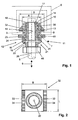
- Fig. 1
- Einen Schnitt durch ein erstes Ausführungsbeispiel einer erfindungsgemässen Anbindevorrichtung;
- Fig. 2
- eine Ansicht eines Hintergreifteils; und
- Fig. 3
- einen Schnitt durch ein zweites Ausführungsbeispiel einer erfindungsgemässen Anbindevorrichtung.
- Grundsätzlich sind in den Figuren gleiche Teile mit den gleichen Bezugszeichen versehen.
- In den
Figuren 1 und 2 ist eine Anbindevorrichtung 11 für eine Gewindestange 5 an einer Montageschiene 6 gezeigt. Die Montageschiene 6 weist eine in der Längserstreckung der Montageschiene 6 verlaufende Montageöffnung 7 auf, die von in einem Abstand A zueinander angeordneten Rändern 8 begrenzt ist. - Die Anbindevorrichtung 11 umfasst ein Hintergreifteil 32 zum bereichsweisen Hintergreifen der die Montageöffnung 7 begrenzenden Ränder 8 und eine Justiereinrichtung 12 für die Gewindestange 5. Die Justiereinrichtung 12 weist ein drehbar in dem Hintergreifteil 32 gelagertes Hülsenelement 13 mit einem Innengewinde 14 für die Gewindestange 5 sowie an einem ersten Endbereich 17 einen radial von dem Hülsenelement 13 abragenden Vorsprung 15 zum Hintergreifen des Hintergreifteils 32 auf. Weiter ist ein drehfest mit dem Hülsenelement 13 verbundenes Einstellelement 21 vorgesehen, das einen dem Hintergreifteil 32 zugewandten Anschlag 23 aufweist. Das Einstellelement 21 weist an seiner Aussenseite eine Sechskantausbildung als Drehangriff 22 für ein Verspannwerkzeug auf. Das Hülsenelement 13 ist begrenzt axial verschieblich zu dem Einstellelement 21 gelagert. Zur Drehmitnahme des Hülsenelementes 13 sind Verbindungsmittel 24 in Form von quer zur Längsachse 26 der Anbindevorrichtung 11 verlaufenden Stifte zwischen dem Einstellelement 21 und dem Hülsenelement 13 vorgesehen. An dem zweiten, dem ersten Endbereich 17 gegenüberliegenden Endbereich 19 des Hülsenelementes 13 ist ein radial von dem Hülsenelement 13 abragender Halteabschnitt 16 für die Verbindung des Hülsenelementes 13 und dem Einstellelement 21 vorgesehen. Der Halteabschnitt 16 des Hülsenelementes 13 bildet zudem einen Axialanschlag für das axial zu dem Hülsenelement 13 verschieblichen Hintergreifteil 32 aus.
- Weiter umfasst die Anbindevorrichtung 11 zwischen dem Hintergreifteil 32 und dem Anschlag 23 des Einstellelementes 21 ein Anschlagelement 41, das mit der Aussenseite der Montageschiene 6 in Anlage bringbar ist.
- Ein Federelement 36 zur Federbeaufschlagung des Hintergreifteils 32 in Richtung des Anschlages 23 des Einstellelementes 21 ist zwischen dem Vorsprung 15 am freien Endbereich 17 des Hülsenelementes 13 und dem Hintergreifteil 32 vorgesehen. Der Vorsprung 15 ist ein Ringelement, das über Verbindungsmittel 18 mit dem Hülsenelement 13 verbunden ist.
- Das Hintergreifteil 32 weist vorteilhaft eine Länge L, die kleiner als der Abstand A der die Montageöffnung 7 der Montageschiene 6 begrenzenden Ränder 8 zueinander ist, sowie eine Breite B auf, die grösser als der Abstand A der Ränder 8 der Montageöffnung 7 zueinander ist. Das Hintergreifteil 32 ist an zwei, einander gegenüberliegenden Seitenrändern 33, die im hintergreifenden Zustand des Hintergreifteils 32 mit der Montageschiene 6 in Anlage kommen, mit einer Profilierung 34 versehen, die als eine Verzahnung ausgebildet ist.
- Zur Montage einer hier nicht dargestellten, an einer Gewindestange 5 angeordneten Rohrschelle wird das Hintergreifteil 32 der Anbindevorrichtung 11, welche bereits vor der Anordnung an der Montageschiene 6 an der Gewindestange 5 aufgeschraubt sein kann, an der gewünschten Stelle in die Montageschiene 6 eingeführt und die gesamte Anbindevorrichtung 11 um ihre Längsachse 26 um 90° verdreht, so dass die Seitenränder 33 des Hintergreifteils 32 die Ränder 8 der Montageöffnung 7 hintergreifen. Die Anbindevorrichtung 11 mit der Gewindestange und Rohrschelle ist entlang der Montageöffnung 7 selbsthemmend verschiebbar. Nun wird die zu befestigende Leitung (hier nicht dargestellt) in der Rohrschelle angeordnet.
- Durch Drehen des Einstellelementes 21 wird das drehbar im Hintergreifteil 32 gelagerte Hülsenelement 13 mitgedreht, wobei die über das mit dem Aussengewinde der Gewindestange 5 in Eingriff stehende Innengewinde 14 des Hülsenelementes 13 die Gewindestange 5 entsprechend der Drehrichtung des Einstellelementes 21 entlang der Längsachse 26 der Anbindevorrichtung 11 in Richtung des Doppelpfeils 9 zur Montageschiene 6 hin oder davon weg verschoben wird. Dadurch wird die Position der in der Rohrschelle angeordneten Leitung senkrecht zur Längsrichtung der Montageschiene 6 eingestellt. Da die Gewindestange 5 beim Justieren nicht mitdreht, kann der an der Gewindestange 5 festgelegte Gegenstand, wie beispielsweise eine in einer Rohrschelle eingelegte Leitung während dem Justiervorgang an der Gewindestange 5 verbleiben. Nach der Justierung der Gewindestange 5 wird eine auf die Gewindestange 5 aufgeschraubte Sicherungsmutter 46 mit dem Einstellelement 21 in Anlage gebracht. Bei einem weiteren Schraubvorgang der Sicherungsmutter 46 in Richtung des Einstellelementes 21 wird das Hintergreifteil 32 und somit die Anbindevorrichtung 11 mit der Montageschiene 6 verspannt, wobei Bereiche der die Montageöffnung 7 begrenzenden Ränder 8 zwischen dem Hintergreifteil 32 und dem Anschlag 23 des Einstellelementes 21 beziehungsweise dem Anschlagelement 41 eingeklemmt werden.
- Bei der in der
Figur 3 gezeigten Ausführungsform der Anbindevorrichtung 51 umfasst die Justiereinrichtung 52 ein Einstellelement 61 mit einer Aufnahme 65, die zur Drehmitnahme des Hülsenelementes 53 und zur lösbaren Kupplung mit dem Hülsenelement 53 Kupplungsflächen 66 aufweist. Das Hülsenelement 53 ist mit einem Abschnitt 56 versehen, der entsprechend ausgebildete Gegenkupplungsflächen 57 aufweist. Weiter ist das Einstellelement 61 mit einem Innengewindeabschnitt 67 versehen, womit das Einstellelement 61 auf die Gewindestange 5 aufschraubbar ist. In einer alternativen Ausführung dazu weist das Einstellelement an seinem Anschlag eine lösbare Schnappeinrichtung auf, die in eine entsprechende Gegeneinrichtung, wie beispielsweise eine Nut, an dem Hülsenelement eingreift.
Claims (7)
- Anbindevorrichtung für eine Gewindestange (5) an einer Montageschiene (6), die eine von Rändern (8) begrenzte Montageöffnung (7) aufweist, mit einem Hintergreifteil (32) zum bereichsweisen Hintergreifen der die Montageöffnung (7) begrenzenden Ränder (8) und einer Justiereinrichtung (12; 52) für die Gewindestange (5), wobei
die Justiereinrichtung (12; 52) ein drehbar in dem Hintergreifteil (32) gelagertes Hülsenelement (13; 53) mit einem Innengewinde (14) für die Gewindestange (5) sowie an einem ersten Endbereich (17) einen radial von dem Hülsenelement (13; 53) abragenden Vorsprung (15) zum Hintergreifen des Hintergreifteils (32) aufweist,
und wobei ein drehfest mit dem Hülsenelement (13; 53) verbundenes Einstellelement (21; 61) vorgesehen ist, das einen dem Hintergreifteil (32) zugewandten Anschlag (23) aufweist, dadurch gekennzeichnet,
dass ein Federelement (36) zur Federbeaufschlagung des Hintergreifteils (32) in Richtung des Anschlages (23) des Einstellelementes (21) zwischen dem Vorsprung (15) am ersten Endbereich (17) des Hülsenelementes (13) und dem Hintergreifteil (32) vorgesehen ist. - Anbindevorrichtung nach Anspruch 1, dadurch gekennzeichnet, dass das Hülsenelement (13; 53) begrenzt axial verschieblich zu dem Einstellelement (21; 61) gelagert ist.
- Anbindevorrichtung nach Anspruch 1 oder 2, dadurch gekennzeichnet, dass zur Drehmitnahme des Hülsenelementes (13) Verbindungsmittel (24) zwischen dem Einstellelement (21) und dem Hülsenelement (13) vorgesehen sind.
- Anbindevorrichtung nach Anspruch 1 oder 2, dadurch gekennzeichnet, dass das Einstellelement (61) zur Drehmitnahme des Hülsenelementes (53) Kupplungsflächen (66) zur lösbaren Kupplung mit dem Hülsenelement (53) aufweist.
- Anbindevorrichtung nach einem der Ansprüche 1 bis 4, dadurch gekennzeichnet, dass ein Anschlagelement (41) zwischen dem Hintergreifteil (32) und dem Anschlag (23) des Einstellelementes (21) vorgesehen ist.
- Anbindevorrichtung nach einem der Ansprüche 1 bis 5, dadurch gekennzeichnet, dass an einem zweiten, dem ersten Endbereich (17) gegenüberliegenden Endbereich (19) des Hülsenelementes (13) ein radial von dem Hülsenelement (13) abragender Halteabschnitt (16) für die Verbindung des Hülsenelementes (13) und dem Einstellelement (21) vorgesehen ist, wobei der Halteabschnitt (16) des Hülsenelementes (13) einen Axialanschlag für das axial zu dem Hülsenelement (13) verschiebliche Hintergreifteil (32) ausbildet.
- Anbindevorrichtung nach einem der vorstehenden Ansprüche, dadurch gekennzeichnet, dass der Vorsprung (15) von einem mit dem Hülsenelement (13) verbundenen Ringelement gebildet ist.
Applications Claiming Priority (1)
| Application Number | Priority Date | Filing Date | Title |
|---|---|---|---|
| DE102007000388A DE102007000388A1 (de) | 2007-07-18 | 2007-07-18 | Anbindevorrichtung |
Publications (3)
| Publication Number | Publication Date |
|---|---|
| EP2017484A2 EP2017484A2 (de) | 2009-01-21 |
| EP2017484A3 EP2017484A3 (de) | 2010-03-17 |
| EP2017484B1 true EP2017484B1 (de) | 2011-12-21 |
Family
ID=39930641
Family Applications (1)
| Application Number | Title | Priority Date | Filing Date |
|---|---|---|---|
| EP08104110A Not-in-force EP2017484B1 (de) | 2007-07-18 | 2008-05-27 | Anbindevorrichtung |
Country Status (4)
| Country | Link |
|---|---|
| EP (1) | EP2017484B1 (de) |
| AT (1) | ATE538319T1 (de) |
| DE (1) | DE102007000388A1 (de) |
| ES (1) | ES2376373T3 (de) |
Families Citing this family (1)
| Publication number | Priority date | Publication date | Assignee | Title |
|---|---|---|---|---|
| DE102009000736A1 (de) * | 2009-02-10 | 2010-08-19 | Hilti Aktiengesellschaft | Befestigungsvorrichtung zur Anordnung eines Stangenelementes an einer Montageschiene |
Family Cites Families (3)
| Publication number | Priority date | Publication date | Assignee | Title |
|---|---|---|---|---|
| DE3823000C2 (de) | 1988-07-07 | 1996-02-29 | Wolfgang Halpaus | Befestigungselement |
| DE59814202D1 (de) * | 1997-09-26 | 2008-05-15 | Wolfgang Halpaus | Befestigungselement |
| DE29820923U1 (de) * | 1997-12-01 | 1999-02-25 | Halpaus, Wolfgang, 68519 Viernheim | Befestigungselement |
-
2007
- 2007-07-18 DE DE102007000388A patent/DE102007000388A1/de not_active Withdrawn
-
2008
- 2008-05-27 EP EP08104110A patent/EP2017484B1/de not_active Not-in-force
- 2008-05-27 AT AT08104110T patent/ATE538319T1/de active
- 2008-05-27 ES ES08104110T patent/ES2376373T3/es active Active
Also Published As
| Publication number | Publication date |
|---|---|
| ES2376373T3 (es) | 2012-03-13 |
| DE102007000388A1 (de) | 2009-01-22 |
| ATE538319T1 (de) | 2012-01-15 |
| EP2017484A3 (de) | 2010-03-17 |
| EP2017484A2 (de) | 2009-01-21 |
Similar Documents
| Publication | Publication Date | Title |
|---|---|---|
| EP2218924B1 (de) | Befestigungsvorrichtung zur Anordnung an einer Montageschiene | |
| DE1900078C3 (de) | Schnellbefestigungsvorrichtung | |
| EP1426636B1 (de) | Schnellmontagemutter | |
| EP2500587A1 (de) | Befestigungsvorrichtung zur Anordnung an einer Montageschiene | |
| EP1201941A2 (de) | Schienenanbinder | |
| EP3374648B1 (de) | Verbindungsbaugruppe für montageschienen | |
| DE102007013438B4 (de) | Blumenkastenhalterung mit einer Klemmvorrichtung | |
| EP3673181A1 (de) | Schnellverschraubung, insbesondere zum verbinden von mehrteiligen baugruppen | |
| DE102013113735A1 (de) | Befestiger, Befestigungssystem und Verfahren zur Montage eines Befestigers an einer Montageschiene | |
| WO2016012081A1 (de) | Befestiger für eine montageschiene | |
| DE19946890C2 (de) | Halteelement zur unverlierbaren Halterung von Kopfschrauben | |
| EP2017485B1 (de) | Anbindevorrichtung | |
| DE3823000C2 (de) | Befestigungselement | |
| EP2228552A1 (de) | Befestigungsvorrichtung zur Anordnung an einer Montageschiene | |
| EP3144544B1 (de) | Gelenkanordnung zur positionierung von bauteilen | |
| EP2017484B1 (de) | Anbindevorrichtung | |
| DE202007013500U1 (de) | Verbinder sowie Anordnung von zwei mit einem solchen Verbinder verbundenen Gegenständen | |
| DE102011115627B4 (de) | Spreizvorrichtung | |
| DE102014217781A1 (de) | Vorrichtung zum Befestigen eines Verkleidungselements | |
| EP2221490B1 (de) | Einteiliges Befestigungselement zur Anordnung eines Stangenelementes an einer Montageschiene | |
| DE102020209227B4 (de) | Rohrschelle zur Befestigung eines Rohres an einer Wand | |
| DE19958104C2 (de) | Vorrichtung zum Verbinden zweier Teile | |
| WO2017021182A1 (de) | Lenksäule für ein kraftfahrzeug | |
| EP2309136A2 (de) | Schienenanschlusselement | |
| DE102005037200A1 (de) | Rohrschelle |
Legal Events
| Date | Code | Title | Description |
|---|---|---|---|
| PUAI | Public reference made under article 153(3) epc to a published international application that has entered the european phase |
Free format text: ORIGINAL CODE: 0009012 |
|
| AK | Designated contracting states |
Kind code of ref document: A2 Designated state(s): AT BE BG CH CY CZ DE DK EE ES FI FR GB GR HR HU IE IS IT LI LT LU LV MC MT NL NO PL PT RO SE SI SK TR |
|
| AX | Request for extension of the european patent |
Extension state: AL BA MK RS |
|
| PUAL | Search report despatched |
Free format text: ORIGINAL CODE: 0009013 |
|
| AK | Designated contracting states |
Kind code of ref document: A3 Designated state(s): AT BE BG CH CY CZ DE DK EE ES FI FR GB GR HR HU IE IS IT LI LT LU LV MC MT NL NO PL PT RO SE SI SK TR |
|
| AX | Request for extension of the european patent |
Extension state: AL BA MK RS |
|
| 17P | Request for examination filed |
Effective date: 20100917 |
|
| 17Q | First examination report despatched |
Effective date: 20101012 |
|
| AKX | Designation fees paid |
Designated state(s): AT BE BG CH CY CZ DE DK EE ES FI FR GB GR HR HU IE IS IT LI LT LU LV MC MT NL NO PL PT RO SE SI SK TR |
|
| GRAP | Despatch of communication of intention to grant a patent |
Free format text: ORIGINAL CODE: EPIDOSNIGR1 |
|
| GRAS | Grant fee paid |
Free format text: ORIGINAL CODE: EPIDOSNIGR3 |
|
| GRAA | (expected) grant |
Free format text: ORIGINAL CODE: 0009210 |
|
| AK | Designated contracting states |
Kind code of ref document: B1 Designated state(s): AT BE BG CH CY CZ DE DK EE ES FI FR GB GR HR HU IE IS IT LI LT LU LV MC MT NL NO PL PT RO SE SI SK TR |
|
| REG | Reference to a national code |
Ref country code: GB Ref legal event code: FG4D Free format text: NOT ENGLISH |
|
| REG | Reference to a national code |
Ref country code: CH Ref legal event code: EP |
|
| REG | Reference to a national code |
Ref country code: AT Ref legal event code: REF Ref document number: 538319 Country of ref document: AT Kind code of ref document: T Effective date: 20120115 |
|
| REG | Reference to a national code |
Ref country code: IE Ref legal event code: FG4D |
|
| REG | Reference to a national code |
Ref country code: DE Ref legal event code: R096 Ref document number: 502008005916 Country of ref document: DE Effective date: 20120308 |
|
| REG | Reference to a national code |
Ref country code: ES Ref legal event code: FG2A Ref document number: 2376373 Country of ref document: ES Kind code of ref document: T3 Effective date: 20120313 |
|
| REG | Reference to a national code |
Ref country code: NL Ref legal event code: VDEP Effective date: 20111221 |
|
| PG25 | Lapsed in a contracting state [announced via postgrant information from national office to epo] |
Ref country code: LT Free format text: LAPSE BECAUSE OF FAILURE TO SUBMIT A TRANSLATION OF THE DESCRIPTION OR TO PAY THE FEE WITHIN THE PRESCRIBED TIME-LIMIT Effective date: 20111221 Ref country code: NO Free format text: LAPSE BECAUSE OF FAILURE TO SUBMIT A TRANSLATION OF THE DESCRIPTION OR TO PAY THE FEE WITHIN THE PRESCRIBED TIME-LIMIT Effective date: 20120321 |
|
| LTIE | Lt: invalidation of european patent or patent extension |
Effective date: 20111221 |
|
| PG25 | Lapsed in a contracting state [announced via postgrant information from national office to epo] |
Ref country code: GR Free format text: LAPSE BECAUSE OF FAILURE TO SUBMIT A TRANSLATION OF THE DESCRIPTION OR TO PAY THE FEE WITHIN THE PRESCRIBED TIME-LIMIT Effective date: 20120322 Ref country code: HR Free format text: LAPSE BECAUSE OF FAILURE TO SUBMIT A TRANSLATION OF THE DESCRIPTION OR TO PAY THE FEE WITHIN THE PRESCRIBED TIME-LIMIT Effective date: 20111221 Ref country code: SE Free format text: LAPSE BECAUSE OF FAILURE TO SUBMIT A TRANSLATION OF THE DESCRIPTION OR TO PAY THE FEE WITHIN THE PRESCRIBED TIME-LIMIT Effective date: 20111221 Ref country code: NL Free format text: LAPSE BECAUSE OF FAILURE TO SUBMIT A TRANSLATION OF THE DESCRIPTION OR TO PAY THE FEE WITHIN THE PRESCRIBED TIME-LIMIT Effective date: 20111221 Ref country code: SI Free format text: LAPSE BECAUSE OF FAILURE TO SUBMIT A TRANSLATION OF THE DESCRIPTION OR TO PAY THE FEE WITHIN THE PRESCRIBED TIME-LIMIT Effective date: 20111221 Ref country code: LV Free format text: LAPSE BECAUSE OF FAILURE TO SUBMIT A TRANSLATION OF THE DESCRIPTION OR TO PAY THE FEE WITHIN THE PRESCRIBED TIME-LIMIT Effective date: 20111221 |
|
| PG25 | Lapsed in a contracting state [announced via postgrant information from national office to epo] |
Ref country code: CY Free format text: LAPSE BECAUSE OF FAILURE TO SUBMIT A TRANSLATION OF THE DESCRIPTION OR TO PAY THE FEE WITHIN THE PRESCRIBED TIME-LIMIT Effective date: 20111221 |
|
| REG | Reference to a national code |
Ref country code: IE Ref legal event code: FD4D |
|
| PG25 | Lapsed in a contracting state [announced via postgrant information from national office to epo] |
Ref country code: CZ Free format text: LAPSE BECAUSE OF FAILURE TO SUBMIT A TRANSLATION OF THE DESCRIPTION OR TO PAY THE FEE WITHIN THE PRESCRIBED TIME-LIMIT Effective date: 20111221 Ref country code: BG Free format text: LAPSE BECAUSE OF FAILURE TO SUBMIT A TRANSLATION OF THE DESCRIPTION OR TO PAY THE FEE WITHIN THE PRESCRIBED TIME-LIMIT Effective date: 20120321 Ref country code: IS Free format text: LAPSE BECAUSE OF FAILURE TO SUBMIT A TRANSLATION OF THE DESCRIPTION OR TO PAY THE FEE WITHIN THE PRESCRIBED TIME-LIMIT Effective date: 20120421 Ref country code: EE Free format text: LAPSE BECAUSE OF FAILURE TO SUBMIT A TRANSLATION OF THE DESCRIPTION OR TO PAY THE FEE WITHIN THE PRESCRIBED TIME-LIMIT Effective date: 20111221 Ref country code: SK Free format text: LAPSE BECAUSE OF FAILURE TO SUBMIT A TRANSLATION OF THE DESCRIPTION OR TO PAY THE FEE WITHIN THE PRESCRIBED TIME-LIMIT Effective date: 20111221 Ref country code: IE Free format text: LAPSE BECAUSE OF FAILURE TO SUBMIT A TRANSLATION OF THE DESCRIPTION OR TO PAY THE FEE WITHIN THE PRESCRIBED TIME-LIMIT Effective date: 20111221 |
|
| PG25 | Lapsed in a contracting state [announced via postgrant information from national office to epo] |
Ref country code: PL Free format text: LAPSE BECAUSE OF FAILURE TO SUBMIT A TRANSLATION OF THE DESCRIPTION OR TO PAY THE FEE WITHIN THE PRESCRIBED TIME-LIMIT Effective date: 20111221 Ref country code: PT Free format text: LAPSE BECAUSE OF FAILURE TO SUBMIT A TRANSLATION OF THE DESCRIPTION OR TO PAY THE FEE WITHIN THE PRESCRIBED TIME-LIMIT Effective date: 20120423 Ref country code: RO Free format text: LAPSE BECAUSE OF FAILURE TO SUBMIT A TRANSLATION OF THE DESCRIPTION OR TO PAY THE FEE WITHIN THE PRESCRIBED TIME-LIMIT Effective date: 20111221 |
|
| PLBE | No opposition filed within time limit |
Free format text: ORIGINAL CODE: 0009261 |
|
| STAA | Information on the status of an ep patent application or granted ep patent |
Free format text: STATUS: NO OPPOSITION FILED WITHIN TIME LIMIT |
|
| PG25 | Lapsed in a contracting state [announced via postgrant information from national office to epo] |
Ref country code: DK Free format text: LAPSE BECAUSE OF FAILURE TO SUBMIT A TRANSLATION OF THE DESCRIPTION OR TO PAY THE FEE WITHIN THE PRESCRIBED TIME-LIMIT Effective date: 20111221 |
|
| 26N | No opposition filed |
Effective date: 20120924 |
|
| BERE | Be: lapsed |
Owner name: HILTI AKTIENGESELLSCHAFT Effective date: 20120531 |
|
| PG25 | Lapsed in a contracting state [announced via postgrant information from national office to epo] |
Ref country code: MC Free format text: LAPSE BECAUSE OF NON-PAYMENT OF DUE FEES Effective date: 20120531 |
|
| REG | Reference to a national code |
Ref country code: DE Ref legal event code: R097 Ref document number: 502008005916 Country of ref document: DE Effective date: 20120924 |
|
| PG25 | Lapsed in a contracting state [announced via postgrant information from national office to epo] |
Ref country code: BE Free format text: LAPSE BECAUSE OF NON-PAYMENT OF DUE FEES Effective date: 20120531 |
|
| PG25 | Lapsed in a contracting state [announced via postgrant information from national office to epo] |
Ref country code: FI Free format text: LAPSE BECAUSE OF FAILURE TO SUBMIT A TRANSLATION OF THE DESCRIPTION OR TO PAY THE FEE WITHIN THE PRESCRIBED TIME-LIMIT Effective date: 20111221 |
|
| PG25 | Lapsed in a contracting state [announced via postgrant information from national office to epo] |
Ref country code: MT Free format text: LAPSE BECAUSE OF FAILURE TO SUBMIT A TRANSLATION OF THE DESCRIPTION OR TO PAY THE FEE WITHIN THE PRESCRIBED TIME-LIMIT Effective date: 20111221 |
|
| PG25 | Lapsed in a contracting state [announced via postgrant information from national office to epo] |
Ref country code: LU Free format text: LAPSE BECAUSE OF NON-PAYMENT OF DUE FEES Effective date: 20120527 |
|
| PG25 | Lapsed in a contracting state [announced via postgrant information from national office to epo] |
Ref country code: HU Free format text: LAPSE BECAUSE OF FAILURE TO SUBMIT A TRANSLATION OF THE DESCRIPTION OR TO PAY THE FEE WITHIN THE PRESCRIBED TIME-LIMIT Effective date: 20080527 |
|
| PGFP | Annual fee paid to national office [announced via postgrant information from national office to epo] |
Ref country code: GB Payment date: 20140521 Year of fee payment: 7 |
|
| PGFP | Annual fee paid to national office [announced via postgrant information from national office to epo] |
Ref country code: FR Payment date: 20140509 Year of fee payment: 7 Ref country code: TR Payment date: 20140429 Year of fee payment: 7 Ref country code: AT Payment date: 20140428 Year of fee payment: 7 Ref country code: IT Payment date: 20140522 Year of fee payment: 7 Ref country code: ES Payment date: 20140411 Year of fee payment: 7 Ref country code: CH Payment date: 20140513 Year of fee payment: 7 |
|
| REG | Reference to a national code |
Ref country code: CH Ref legal event code: PL |
|
| REG | Reference to a national code |
Ref country code: AT Ref legal event code: MM01 Ref document number: 538319 Country of ref document: AT Kind code of ref document: T Effective date: 20150527 |
|
| GBPC | Gb: european patent ceased through non-payment of renewal fee |
Effective date: 20150527 |
|
| PG25 | Lapsed in a contracting state [announced via postgrant information from national office to epo] |
Ref country code: IT Free format text: LAPSE BECAUSE OF NON-PAYMENT OF DUE FEES Effective date: 20150527 Ref country code: CH Free format text: LAPSE BECAUSE OF NON-PAYMENT OF DUE FEES Effective date: 20150531 Ref country code: LI Free format text: LAPSE BECAUSE OF NON-PAYMENT OF DUE FEES Effective date: 20150531 |
|
| REG | Reference to a national code |
Ref country code: FR Ref legal event code: ST Effective date: 20160129 |
|
| PG25 | Lapsed in a contracting state [announced via postgrant information from national office to epo] |
Ref country code: AT Free format text: LAPSE BECAUSE OF NON-PAYMENT OF DUE FEES Effective date: 20150527 |
|
| PG25 | Lapsed in a contracting state [announced via postgrant information from national office to epo] |
Ref country code: GB Free format text: LAPSE BECAUSE OF NON-PAYMENT OF DUE FEES Effective date: 20150527 |
|
| PG25 | Lapsed in a contracting state [announced via postgrant information from national office to epo] |
Ref country code: FR Free format text: LAPSE BECAUSE OF NON-PAYMENT OF DUE FEES Effective date: 20150601 |
|
| REG | Reference to a national code |
Ref country code: ES Ref legal event code: FD2A Effective date: 20160627 |
|
| PG25 | Lapsed in a contracting state [announced via postgrant information from national office to epo] |
Ref country code: ES Free format text: LAPSE BECAUSE OF NON-PAYMENT OF DUE FEES Effective date: 20150528 |
|
| PG25 | Lapsed in a contracting state [announced via postgrant information from national office to epo] |
Ref country code: TR Free format text: LAPSE BECAUSE OF NON-PAYMENT OF DUE FEES Effective date: 20150527 |
|
| PGFP | Annual fee paid to national office [announced via postgrant information from national office to epo] |
Ref country code: DE Payment date: 20230519 Year of fee payment: 16 |
|
| REG | Reference to a national code |
Ref country code: DE Ref legal event code: R119 Ref document number: 502008005916 Country of ref document: DE |
|
| PG25 | Lapsed in a contracting state [announced via postgrant information from national office to epo] |
Ref country code: DE Free format text: LAPSE BECAUSE OF NON-PAYMENT OF DUE FEES Effective date: 20241203 |