EP2017049A2 - Apparatus for manufacturing prefabricated concrete elements with an assembly line - Google Patents
Apparatus for manufacturing prefabricated concrete elements with an assembly line Download PDFInfo
- Publication number
- EP2017049A2 EP2017049A2 EP08012795A EP08012795A EP2017049A2 EP 2017049 A2 EP2017049 A2 EP 2017049A2 EP 08012795 A EP08012795 A EP 08012795A EP 08012795 A EP08012795 A EP 08012795A EP 2017049 A2 EP2017049 A2 EP 2017049A2
- Authority
- EP
- European Patent Office
- Prior art keywords
- station
- pallet
- formwork
- production line
- takes place
- Prior art date
- Legal status (The legal status is an assumption and is not a legal conclusion. Google has not performed a legal analysis and makes no representation as to the accuracy of the status listed.)
- Ceased
Links
- 238000004519 manufacturing process Methods 0.000 title claims abstract description 65
- 239000004567 concrete Substances 0.000 title claims abstract description 24
- 238000004140 cleaning Methods 0.000 claims abstract description 13
- 238000000034 method Methods 0.000 claims abstract description 13
- 230000002787 reinforcement Effects 0.000 claims abstract description 10
- 238000009415 formwork Methods 0.000 claims description 50
- 230000001360 synchronised effect Effects 0.000 claims description 27
- 230000002093 peripheral effect Effects 0.000 claims description 18
- 239000011178 precast concrete Substances 0.000 claims description 14
- 230000001788 irregular Effects 0.000 claims description 4
- 238000006073 displacement reaction Methods 0.000 claims description 3
- 238000009434 installation Methods 0.000 claims 9
- 238000009416 shuttering Methods 0.000 description 9
- 229920006328 Styrofoam Polymers 0.000 description 1
- 238000007796 conventional method Methods 0.000 description 1
- 230000010485 coping Effects 0.000 description 1
- 230000013011 mating Effects 0.000 description 1
- 238000012544 monitoring process Methods 0.000 description 1
- 230000008092 positive effect Effects 0.000 description 1
- 238000002360 preparation method Methods 0.000 description 1
- 238000011084 recovery Methods 0.000 description 1
- 239000008261 styrofoam Substances 0.000 description 1
- 230000001960 triggered effect Effects 0.000 description 1
Images


Classifications
-
- B—PERFORMING OPERATIONS; TRANSPORTING
- B28—WORKING CEMENT, CLAY, OR STONE
- B28B—SHAPING CLAY OR OTHER CERAMIC COMPOSITIONS; SHAPING SLAG; SHAPING MIXTURES CONTAINING CEMENTITIOUS MATERIAL, e.g. PLASTER
- B28B15/00—General arrangement or layout of plant ; Industrial outlines or plant installations
-
- B—PERFORMING OPERATIONS; TRANSPORTING
- B28—WORKING CEMENT, CLAY, OR STONE
- B28B—SHAPING CLAY OR OTHER CERAMIC COMPOSITIONS; SHAPING SLAG; SHAPING MIXTURES CONTAINING CEMENTITIOUS MATERIAL, e.g. PLASTER
- B28B17/00—Details of, or accessories for, apparatus for shaping the material; Auxiliary measures taken in connection with such shaping
- B28B17/0063—Control arrangements
- B28B17/0081—Process control
-
- B—PERFORMING OPERATIONS; TRANSPORTING
- B28—WORKING CEMENT, CLAY, OR STONE
- B28B—SHAPING CLAY OR OTHER CERAMIC COMPOSITIONS; SHAPING SLAG; SHAPING MIXTURES CONTAINING CEMENTITIOUS MATERIAL, e.g. PLASTER
- B28B5/00—Producing shaped articles from the material in moulds or on moulding surfaces, carried or formed by, in, or on conveyors irrespective of the manner of shaping
- B28B5/04—Producing shaped articles from the material in moulds or on moulding surfaces, carried or formed by, in, or on conveyors irrespective of the manner of shaping in moulds moved in succession past one or more shaping stations
-
- B—PERFORMING OPERATIONS; TRANSPORTING
- B28—WORKING CEMENT, CLAY, OR STONE
- B28B—SHAPING CLAY OR OTHER CERAMIC COMPOSITIONS; SHAPING SLAG; SHAPING MIXTURES CONTAINING CEMENTITIOUS MATERIAL, e.g. PLASTER
- B28B7/00—Moulds; Cores; Mandrels
- B28B7/0029—Moulds or moulding surfaces not covered by B28B7/0058 - B28B7/36 and B28B7/40 - B28B7/465, e.g. moulds assembled from several parts
- B28B7/0032—Moulding tables or similar mainly horizontal moulding surfaces
-
- B—PERFORMING OPERATIONS; TRANSPORTING
- B28—WORKING CEMENT, CLAY, OR STONE
- B28B—SHAPING CLAY OR OTHER CERAMIC COMPOSITIONS; SHAPING SLAG; SHAPING MIXTURES CONTAINING CEMENTITIOUS MATERIAL, e.g. PLASTER
- B28B7/00—Moulds; Cores; Mandrels
- B28B7/02—Moulds with adjustable parts specially for modifying at will the dimensions or form of the moulded article
Definitions
- the invention relates to a plant for the production of prefabricated concrete elements with a production line, in which the production of the components takes place on pallet shapes, which successively at least a decalcifying station, a cleaning station, a particular automatic formwork station, a concreting station, a reinforcement station and a curing chamber of a production line.
- Such systems are used to produce flat concrete elements, in particular ceiling and wall elements.
- the production of concrete elements takes place on pallet forms, also called production pallets, which successively pass through several stations of a production line.
- pallet forms also called production pallets
- the prefabricated concrete element is dismantled and the formwork profiles are removed from the pallet form.
- the cleaning of the pallet forms before they are equipped at the Schalstation with new formwork.
- the pallet shape is fed to the curing chamber, in which the setting of the concrete takes place.
- this object is achieved in that the feed of the pallet shapes takes place synchronously from the de-scaling station to the curing chamber. Characterized in that the feed takes place according to the invention at the same time, can be dispensed with the arrangement of buffer stations entirely and production bottlenecks can be avoided.
- a further embodiment of the invention provides that in the course of the production line, one or more blind station (s) on which (preferably) no work steps are (is) arranged, wherein attempts by the applicant have shown that an arrangement of a dummy station between the cleaning and formwork station and / or the formwork and concreting station is particularly advantageous for a smooth passage of the pallet shape through the production line.
- the blind stations serve to bridge longer distances between two processing stations. This is necessary because, as a result of the synchronous feed of all pallet shapes, a longer transport time between two stations due to a longer distance would shorten the time available for coping with the subsequent work cycle.
- the feed of the pallet shapes takes place synchronously at all stations of the production line, wherein it has turned out to be advantageous if the pallet forms pass through the production line all around.
- a basic idea of the invention is therefore to make the pallet shapes synchronous, at least from the decaling station to the curing chamber, preferably at all stations of the production line. to move at the same time.
- the clock of the synchronous shift will depend on the time of the power strokes at the individual stations and the transport time between the individual stations of the production line.
- the synchronous feed of the pallet forms takes place at regular time intervals, wherein the cycle of the synchronous shift is defined as a function of a predetermined maximum time per working cycle at the individual stations of the production line and the transport time of the pallet forms between the individual stations of the production line.
- the timing of the synchronous shift which corresponds to the time between the individual feeds, is composed of the time of the power strokes and the transport time between the individual stations.
- the maximum time per power cycle at the individual stations of the production line is less than 6 minutes, preferably less than 4.5 minutes, whereby a particularly high utilization of the production line can be achieved if the maximum time is less than 4 minutes, preferably at about 3.5 minutes.
- the cycle time of the synchronous shift can also be shortened, it being provided according to a further embodiment of the invention that the cycle time of the synchronous shift between 3.5 and 5.5 minutes, preferably about 4 , 5 minutes.
- Another embodiment of the invention provides that the synchronous feed of the pallet forms takes place at irregular time intervals, wherein the triggering of the synchronous shift takes place in dependence on the time of the longest working cycle of the individual stations of the production line.
- this embodiment is based on the time required for the power stroke at the slowest station. In contrast to the above-described embodiment, however, no maximum time is determined for this time-consuming station or Predetermined, but there is the synchronous feed of the pallet forms after completion of the power stroke at the slowest station.
- the synchronization shift can be triggered automatically, preferably by means of a system control, or manually.
- a maximum of three formworks are arranged on a pallet form, wherein preferably a formwork for a concrete precast element to be produced is preferably arranged centrally on a pallet form.
- the inventive arrangement of a maximum of three, preferably one formwork per pallet shape improved automation is achieved on many stations, since only one element must be edited. If the arrangement also takes place in the center, the working distances are shortened and the central position of the formwork can serve as a fixed reference point for a shuttering robot.
- precast concrete element follows a completely new logic. While as many precast concrete elements as possible have been produced on a production pallet according to the prior art, according to the invention only one concrete element per pallet form is produced. The poorer utilization of the individual pallet shapes brings the advantage a fixed maximum working time per cycle with it, whereby a consistent automation of the production line is made possible, so that ultimately with the inventive method in the same time at least as many precast concrete elements can be produced as with the conventional method.
- the method according to the invention allows a tremendous reduction in personnel, whereby the total costs can be considerably reduced.
- the maximum time per stroke allows a predictable turnaround time for a pallet shape through the production line, thereby avoiding production bottlenecks.
- An embodiment variant of the invention therefore provides that exclusively substantially identically designed shuttering profiles with standard lengths are used to form a substantially closed inner circumferential edge, the lengths of the shuttering profiles used being different from the side lengths of the precast concrete element to be produced.
- fitting elements is completely dispensed with, which of course has a positive effect on the time for the power stroke at the formwork station.
- At least one side of the inner peripheral edge of the formwork is formed by at least two substantially identically formed formwork profiles with standard lengths, which are arranged one behind the other in the longitudinal direction.
- one side of the formwork is formed by at least two series-laid shuttering profiles of standardized length.
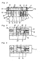
- Plant 1 shown comprises several stations, which are arranged such that the pallet molds 21, on which the precast concrete elements are produced, these stations in the sense of a production line in particular circulating through.
- This production line comprises a de-scaling station 2, in the region of which a demolition cross-piece 3 is arranged. Subsequent to the de-scaling station 2, a shuttering removal station 4 follows, in which the shuttering profiles 10 are removed from the pallet mold 21. This is followed by the cleaning station 6, which is associated with a cleaning and ⁇ lungsvorraum 5.
- the pallet molds 21 are conveyed to the formwork station 7.
- the shells of concrete precast elements by means of a formwork robot 8, which fetches the Abschalprofile 10 from the formwork bearing 9 and positioned on the pallet mold 21 located in the formwork station 7.
- the Abschalprofile 10 go through after removal of the pallet mold 21 in the Schalungsentfemungsstation 4 a transport and cleaning line 22 before they are deposited in the formwork warehouse.
- the formwork station 7 is followed by a blind station 12, at which no work is carried out.
- concreting station 14 which is assigned to the concreting device 13, by means of which the concrete is introduced into the formwork 11.
- the concreting station 14 is again followed by a dummy station 12 and thereupon the reinforcement station 15, in which by means of a positioning device 16, which in the reinforcement preparation station 18th prepared reinforcements in the already concrete, but not yet set concrete prefabricated element can be introduced.
- the recovery station 15 is followed by the pick-up station 17 and possibly another blind station 12.
- the pallet molds 21 are picked up by the pick-up station 17 or the subsequent blind station 12 and brought into the curing chamber 20, where the precast concrete element cures under supply of hot air. After setting of the concrete, the pallet mold 21 is transferred from the curing chamber 20 in the de-scaling station 2 and there begins a new round through the production line.
- Fig. 1b the transport routes between the individual stations of the production line are shown in a synchronous shift.
- the pallet molds 21 are moved within a minute from one station to the next, wherein the displacement takes place synchronously.
- Fig. 1c are the individual work processes, which must be performed during a power stroke whose maximum production time is set in the illustrated embodiment with 3.5 minutes. It is again at the same time on the demoulding station 3 the demoulding of concrete precast element, on the Schalungsentfemungsstation 4 the Abschalprofile be removed, in the cleaning station 6, the pallet molds 21 are cleaned on the formwork station 7, the production of the formwork 11 by means of Abschalprofile 10, concreting the Prefabricated concrete element takes place in the concreting station 14 with any reworking carried out on the blind station 12 can be on the reinforcement station 15, the reinforcements are introduced, while on the pickup 17 any special reinforcements can be introduced.
- the timing of the synchronous shift is composed of the maximum manufacturing time of 3.5 minutes and the transport time of 1 minute, i. the pallet molds 21 are moved every 4.5 minutes between the synchronously connected stations of the production line.
- the pallet molds 21 used in this embodiment are about 8 m long and 3 m wide, with about 88 pallets in a layer through the production line.
- a pallet occupancy of 11.25 m 2 which corresponds to a precast concrete element with a length of 4.5 m and a width of 2.5 m
- a production of about 1,000 m 2 per shift with a duration of 8 working hours can be achieved with the system 1 according to the invention become.
- the effective production time during one shift is 7 hours, while the cleaning time takes 1 hour.
- the system 1 according to the invention the number of personnel required for the monitoring of the plant can be reduced to up to 3 persons, while in plants according to the prior art, in which the feed of the pallet forms was not synchronized, sometimes up to 20 people were necessary ,
- inventive systems 1 differ from the embodiment according to Fig. 1a to 1c only by the local arrangement of the individual stations of the production line, wherein in the embodiment according to Fig. 2 the stacking device 19 is formed by a stacker crane.
- FIG. 3 illustrated embodiment shows a system 1, with the addition of element ceilings and double walls can be made.
- a dummy station 12 is arranged after the concreting station 14, which is associated with a turning device 23 with a turning frame and suction cups.
- the operation of such Wenderahmen is known per se, which is why a description is omitted here.
- FIG. 4 illustrated embodiment differs from the in Fig. 3 shown example only in that just no such turning device 23 is provided, ie the system according to Fig. 4 serves for the production of flat element ceilings.
- Fig. 5a to 5c are different embodiments of inventive formworks 11, which are arranged on a pallet 21, shown.
- at least three of the formwork 11 forming Abschalprofile 10 project beyond the outer peripheral edge U a , in each case to the section A.
- the outer peripheral edge U a is defined by the Abschal vom 24 opposite longitudinal sides of Abschalprofile 10 and is the inner peripheral edge U I geometrically similar.
- the peripheral edge of the formwork 11 is formed by the Abschalprofilen 10, the Abschalvid 24 of Abschalprofile 10 forming the inner peripheral edge U I , while the Abschalvid 24 opposite sides of Abschalprofile 10 are part of the outer peripheral edge U A.
- Fig. 5a stand all Abschalprofile 10 over the outer peripheral edge U A , while in the Fig. 5b and 5c only three Abschalprofile 10 protrude beyond the outer peripheral edge U A.
- Fig. 6 illustrated embodiment of a formwork 11 according to the invention three sides of the peripheral edge U a of Abschalprofilen 10 are formed with a standardized length.
- the fourth side of the formwork 11 with the side length L is in contrast to the embodiments according to Fig. 5a to 5c not formed by a projecting Abschalprofil 10 but rather by two set in series Abschalprofilen 10.
- a corresponding grid of different Standard lengths for Abschalprofile 10 can be switched with this method almost all required side lengths L of a concrete precast element to be manufactured exclusively with Abschalprofilen 10 standardized length.
- Smaller distances between the series-laid Abschalprofilen 10 play no major role, but the distance between the individual Abschalprofilen should not be greater than 1.5 cm usually to avoid spillage of the concrete.
- the laying of Abschalprofile 10 can be done entirely with a formwork robot 8, where it has been found to be particularly advantageous if only one formwork per pallet 21 is arranged, since then the center M of the pallet 21 as a reference point for the shuttering robot. 8 can serve.
- a very short overall time required for the shelling of concrete precast element is achieved, whereby a total of a short cycle time for the synchronous shift and a particularly efficient automation of the pallet circulation system can be achieved.
Abstract
Description
Die Erfindung betrifft eine Anlage zur Herstellung von Betonfertigbauelementen mit einer Fertigungsstraße, bei der die Herstellung der Bauelemente auf Palettenformen erfolgt, die nacheinander wenigstens eine Entschalungsstation, eine Reinigungsstation, eine insbesondere automatische Schalungsstation, eine Betonierstation, eine Bewehrungsstation und eine Härtekammer einer Fertigungsstraße durchlaufen.The invention relates to a plant for the production of prefabricated concrete elements with a production line, in which the production of the components takes place on pallet shapes, which successively at least a decalcifying station, a cleaning station, a particular automatic formwork station, a concreting station, a reinforcement station and a curing chamber of a production line.
Derartige Anlagen dienen zur Fertigung flächiger Betonelemente, insbesondere Decken- und Wandelemente. Die Fertigung der Betonelemente erfolgt dabei auf Palettenformen, auch Fertigungspaletten genannt, die nacheinander mehrere Stationen einer Fertigungsstraße durchlaufen. In der Fertigungsstraße wird das Betonfertigbauelement entschalt und die Abschalprofile von der Palettenform entfernt. Danach erfolgt in einer weiteren Station die Reinigung der Palettenformen, bevor diese an der Schalstation mit neuen Schalungen bestückt werden. Nach dem Betonieren und dem Einbringen der Bewehrungen wird die Palettenform der Härtekammer zugeführt, in der das Abbinden des Betons erfolgt.Such systems are used to produce flat concrete elements, in particular ceiling and wall elements. The production of concrete elements takes place on pallet forms, also called production pallets, which successively pass through several stations of a production line. In the production line, the prefabricated concrete element is dismantled and the formwork profiles are removed from the pallet form. Thereafter, in another station, the cleaning of the pallet forms, before they are equipped at the Schalstation with new formwork. After concreting and the introduction of the reinforcements, the pallet shape is fed to the curing chamber, in which the setting of the concrete takes place.
Bei den bisher bekannten Anlagen ist bedingt durch die unterschiedlich lange Dauer der Arbeitstakte an den einzelnen Stationen die Anordnung von Pufferstationen, an denen die Palettenform aus dem Umlauf herausgenommen wird, notwendig. Das heißt, es werden nach Stationen mit kürzerem Arbeitstakt, beispielsweise der Entschalungsstation, Pufferzonen vorgesehen, in denen die Palettenformen geparkt werden können, bis die in der Fertigungsstraße nachfolgende Station frei wird.In the previously known systems is due to the different lengths of the duration of the work cycles at the individual stations, the arrangement of buffer stations where the pallet form is taken out of circulation, necessary. That is, after stations with shorter working cycle, such as the de-scaling station, buffer zones are provided in which the pallet shapes can be parked until the station following in the production line becomes free.
Als nachteilig an diesem Stand der Technik hat sich neben der nur sehr schwer bzw. gar nicht berechenbaren Gesamtarbeitszeit für den Durchlauf einer Palettenform zudem das Auftreten von Produktionsstaus, die infolge der ungleichmäßigen Arbeitstakte und der damit verbundenen unregelmäßigen Vorschübe der Palettenformen auftreten können, herausgestellt.A disadvantage of this state of the art, in addition to the only very difficult or even unpredictable total working time for the passage of a pallet shape also the occurrence of production jams, which may occur as a result of uneven work cycles and the associated irregular feeds of the pallet forms, exposed.
Ausgehend von diesem Stand der Technik hat es sich die Erfindung zur Aufgabe gemacht, eine verbesserte Anlage der eingangs erwähnten Art zu schaffen, mit der die vorbeschriebenen Nachteile vermieden werden können und die insbesondere die Berechnung einer Gesamtarbeitszeit für den Durchlauf einer Palettenform durch die Fertigungsstraße erlaubt.Based on this prior art, it has the object of the invention to provide an improved system of the type mentioned above, with which the above-described disadvantages can be avoided and in particular the Calculation of a total working time allowed for the passage of a pallet form through the production line.
Erfindungsgemäß wird diese Aufgabe gelöst, indem der Vorschub der Palettenformen von der Entschalungsstation bis zur Härtekammer synchron erfolgt. Dadurch, dass der Vorschub erfindungsgemäß gleichzeitig erfolgt, kann auf die Anordnung von Pufferstationen zur Gänze verzichtet und können Produktionsstaus vermieden werden.According to the invention, this object is achieved in that the feed of the pallet shapes takes place synchronously from the de-scaling station to the curing chamber. Characterized in that the feed takes place according to the invention at the same time, can be dispensed with the arrangement of buffer stations entirely and production bottlenecks can be avoided.
Ein weiteres Ausführungsbeispiel der Erfindung sieht vor, dass im Verlauf der Fertigungsstraße eine oder mehrere Blindstation(en), an der (denen) vorzugsweise keine Arbeitsschritte erfolgen, angeordnet ist (sind), wobei Versuche der Anmelderin gezeigt haben, dass eine Anordnung einer Blindstation zwischen der Reinigungs- und Schalungsstation und/oder der Schalung- und Betonierstation besonders vorteilhaft für einen gleichmäßigen Durchlauf der Palettenform durch die Fertigungsstraße ist.A further embodiment of the invention provides that in the course of the production line, one or more blind station (s) on which (preferably) no work steps are (is) arranged, wherein attempts by the applicant have shown that an arrangement of a dummy station between the cleaning and formwork station and / or the formwork and concreting station is particularly advantageous for a smooth passage of the pallet shape through the production line.
Die Blindstationen, an denen in der Regel keine Arbeitsschritte ausgeführt werden, dienen zur Überbrückung längerer Wegstrecken zwischen zwei Bearbeitungsstationen. Dies ist deshalb notwendig, da ja infolge des synchronen Vorschubs aller Palettenformen eine durch eine längere Wegstrecke bedingte längere Transportzeit zwischen zwei Stationen die Zeit, die zur Bewältigung des nachfolgenden Arbeitstaktes zur Verfügung steht, verkürzen würde.The blind stations, where usually no work steps are performed, serve to bridge longer distances between two processing stations. This is necessary because, as a result of the synchronous feed of all pallet shapes, a longer transport time between two stations due to a longer distance would shorten the time available for coping with the subsequent work cycle.
Gemäß einem bevorzugten Ausführungsbeispiel der Erfindung ist weiters vorgesehen, dass der Vorschub der Palettenformen an allen Stationen der Fertigungsstraße synchron erfolgt, wobei es sich als günstig herausgestellt hat, wenn die Palettenformen die Fertigungsstrasse umlaufend durchlaufen.According to a preferred embodiment of the invention, it is further provided that the feed of the pallet shapes takes place synchronously at all stations of the production line, wherein it has turned out to be advantageous if the pallet forms pass through the production line all around.
Eine Grundidee der Erfindung besteht also darin, die Palettenformen zumindest von der Entschalungsstation bis zur Härtekammer, vorzugsweise an allen Stationen der Fertigungsstraße, synchron, d.h. gleichzeitig zu verschieben. Dabei wird der Takt der Synchronverschiebung von der Zeit der Arbeitstakte an den einzelnen Stationen sowie der Transportzeit zwischen den einzelnen Stationen der Fertigungsstraße abhängen.A basic idea of the invention is therefore to make the pallet shapes synchronous, at least from the decaling station to the curing chamber, preferably at all stations of the production line. to move at the same time. In this case, the clock of the synchronous shift will depend on the time of the power strokes at the individual stations and the transport time between the individual stations of the production line.
Gemäß einer ersten Ausführungsform der Erfindung ist dabei vorgesehen, dass der synchrone Vorschub der Palettenformen in regelmäßigen Zeitabständen erfolgt, wobei der Takt der Synchronverschiebung in Abhängigkeit einer vorbestimmten Maximalzeit pro Arbeitstakt an den einzelnen Stationen der Fertigungsstraße und der Transportzeit der Palettenformen zwischen den einzelnen Stationen der Fertigungsstrasse festgelegt ist.According to a first embodiment of the invention, it is provided that the synchronous feed of the pallet forms takes place at regular time intervals, wherein the cycle of the synchronous shift is defined as a function of a predetermined maximum time per working cycle at the individual stations of the production line and the transport time of the pallet forms between the individual stations of the production line.
Das heißt, der Takt der Synchronverschiebung, der der Zeit zwischen den einzelnen Vorschüben entspricht, setzt sich aus der Zeit der Arbeitstakte und der Transportzeit zwischen den einzelnen Stationen zusammen.That is, the timing of the synchronous shift, which corresponds to the time between the individual feeds, is composed of the time of the power strokes and the transport time between the individual stations.
Das heißt in der Praxis, dass für den Arbeitstakt der zeitintensivsten Station eine Maximalzeit vorbestimmt wird, zu dieser Maximalzeit für die langsamste Station die Transportzeit zwischen den einzelnen Stationen addiert wird und die daraus resultierende Zeitspanne den Takt der Synchronverschiebung darstellt.This means in practice that a maximum time is predetermined for the working clock of the time-intensive station, the transport time between the individual stations is added to this maximum time for the slowest station and the resulting time interval represents the cycle of the synchronous shift.
Gemäß einem Ausführungsbeispiel der Erfindung ist dabei vorgesehen, dass die Maximalzeit pro Arbeitstakt an den einzelnen Stationen der Fertigungsstraße unter 6 Minuten, vorzugsweise unter 4,5 Minuten liegt, wobei eine besonders hohe Auslastung der Fertigungsstraße erreicht werden kann, wenn die Maximalzeit unter 4 Minuten, vorzugsweise bei etwa 3,5 Minuten liegt. Durch eine günstige Anordnung der einzelnen Stationen der Fertigungsstraße, d.h. die Entfernung zwischen den einzelnen Stationen soll nach Möglichkeit gering gehalten werden, lässt sich die Taktzeit der Synchronverschiebung ebenfalls verkürzen, wobei gemäß einem weiteren Ausführungsbeispiel der Erfindung vorgesehen ist, dass die Taktzeit der Synchronverschiebung zwischen 3,5 und 5,5 Minuten, vorzugsweise etwa 4,5 Minuten, beträgt.According to one exemplary embodiment of the invention, it is provided that the maximum time per power cycle at the individual stations of the production line is less than 6 minutes, preferably less than 4.5 minutes, whereby a particularly high utilization of the production line can be achieved if the maximum time is less than 4 minutes, preferably at about 3.5 minutes. By a convenient arrangement of the individual stations of the production line, i. the distance between the stations should be kept as low as possible, the cycle time of the synchronous shift can also be shortened, it being provided according to a further embodiment of the invention that the cycle time of the synchronous shift between 3.5 and 5.5 minutes, preferably about 4 , 5 minutes.
Eine andere Ausführungsform der Erfindung sieht vor, dass der synchrone Vorschub der Palettenformen in unregelmäßigen Zeitabständen erfolgt, wobei die Auslösung der Synchronverschiebung in Abhängigkeit der Zeit des längsten Arbeitstaktes der einzelnen Stationen der Fertigungsstrasse erfolgt.Another embodiment of the invention provides that the synchronous feed of the pallet forms takes place at irregular time intervals, wherein the triggering of the synchronous shift takes place in dependence on the time of the longest working cycle of the individual stations of the production line.
Auch dieses Ausführungsbeispiel geht von der für den Arbeitstakt an der langsamsten Station benötigten Zeit aus. Im Gegensatz zum vorbeschriebenen Ausführungsbeispiel wird für diese zeitaufwendigste Station jedoch keine Maximalzeit ermittelt bzw. vorbestimmt, sondern erfolgt der synchrone Vorschub der Palettenformen nach Abschluss des Arbeitstaktes an der langsamsten Station.Also, this embodiment is based on the time required for the power stroke at the slowest station. In contrast to the above-described embodiment, however, no maximum time is determined for this time-consuming station or Predetermined, but there is the synchronous feed of the pallet forms after completion of the power stroke at the slowest station.
Unabhängig davon, ob der synchrone Vorschub der Palettenformen in der Fertigungsstraße in einem regelmäßigen oder einem unregelmäßigen Takt erfolgt, kann die Auslösung der Synchronverschiebung automatisch, vorzugsweise mittels einer Anlagensteuerung, oder manuell erfolgen.Regardless of whether the synchronous feed of the pallet shapes in the production line takes place in a regular or an irregular cycle, the synchronization shift can be triggered automatically, preferably by means of a system control, or manually.
Weiters wird ein Verfahren zur Herstellung von Betonfertigbauelementen mit einer erfindungsgemäßen Anlage angegeben.Furthermore, a method for producing precast concrete elements with a system according to the invention is specified.
Bei den bisher bekannten Einschalmethoden werden soviele Schalungen wie möglich auf einer Palette produziert, d.h. man maximiert die so genannte Palettenauslastung. Dabei wird das erste Element normalerweise bündig in einem Eck platziert, das zweite daran angrenzend, usw. Diese Methode bringt den Nachteil mit sich, dass der Arbeitstakt an der Schalungsstation je nach Schalung unterschiedlich viel Zeit in Anspruch nimmt, wodurch die Berechnung einer Gesamtarbeitszeit für den Durchlauf einer Palettenform durch die Fertigungsstraße fast unmöglich ist.In the previously known Einschalmethoden as many forms are produced as possible on a pallet, i. one maximizes the so-called pallet utilization. In this case, the first element is normally placed flush in one corner, the second adjacent thereto, etc. This method has the disadvantage that the working cycle at the formwork station takes different amounts of time depending on the formwork, whereby the calculation of a total working time for the Passing a pallet form through the production line is almost impossible.
Neuerungsgemäß wird deshalb vorgeschlagen, dass auf einer Palettenform höchstens drei Schalungen angeordnet werden, wobei bevorzugterweise auf einer Palettenform genau eine Schalung für ein herzustellendes Betonfertigbauelement vorzugsweise mittig angeordnet wird.According to the innovation it is therefore proposed that a maximum of three formworks are arranged on a pallet form, wherein preferably a formwork for a concrete precast element to be produced is preferably arranged centrally on a pallet form.
Durch die erfindungsgemäße Anordnung von maximal drei, vorzugsweise einer Schalung pro Palettenform wird eine verbesserte Automatisierung auf vielen Stationen erreicht, da immer nur ein Element bearbeitet werden muss. Erfolgt die Anordnung zudem mittig, verkürzen sich die Arbeitswege und kann die mittige Position der Schalung als fixer Bezugspunkt für einen Schalungsroboter dienen.The inventive arrangement of a maximum of three, preferably one formwork per pallet shape improved automation is achieved on many stations, since only one element must be edited. If the arrangement also takes place in the center, the working distances are shortened and the central position of the formwork can serve as a fixed reference point for a shuttering robot.
Mit dem erfindungsgemäßen Verfahren folgt die Produktion von Betonfertigbauelement einer vollkommen neuen Logik. Während nach dem Stand der Technik so viele Betonfertigbauelemente wie möglich auf einer Fertigungspalette produziert wurden, wird erfindungsgemäß nur mehr ein Betorifertigbauelement pro Palettenform produziert. Die schlechtere Auslastung der einzelnen Palettenformen bringt den Vorteil einer festen maximalen Arbeitszeit pro Arbeitstakt mit sich, wodurch eine konsequente Automatisierung der Fertigungsstraße ermöglicht wird, sodass schlussendlich mit dem erfindungsgemäßen Verfahren in derselben Zeit mindestens gleich viele Betonfertigbauelemente hergestellt werden können wie mit den herkömmlichen Verfahren.With the method according to the invention, the production of precast concrete element follows a completely new logic. While as many precast concrete elements as possible have been produced on a production pallet according to the prior art, according to the invention only one concrete element per pallet form is produced. The poorer utilization of the individual pallet shapes brings the advantage a fixed maximum working time per cycle with it, whereby a consistent automation of the production line is made possible, so that ultimately with the inventive method in the same time at least as many precast concrete elements can be produced as with the conventional method.
Allerdings ermöglicht das neuerungsgemäße Verfahren aufgrund der konsequenten Automatisierung eine enorme Personaleinsparung, wodurch die Gesamtkosten erheblich reduziert werden können. Zudem ermöglicht die Maximalzeit pro Arbeitstakt eine berechenbare Durchlaufzeit für eine Palettenform durch die Fertigungsstraße, wodurch Produktionsstaus vermieden werden können.However, due to the consistent automation, the method according to the invention allows a tremendous reduction in personnel, whereby the total costs can be considerably reduced. In addition, the maximum time per stroke allows a predictable turnaround time for a pallet shape through the production line, thereby avoiding production bottlenecks.
Bei den bisher bekannten Einschalmethoden wurden möglichst viele Seiten des herzustellenden Betonfertigbauelementes von Abschalprofilen mit standardisierten Längen gebildet. Da die standardisierten Längen der Abschalprofile in den wenigsten Fällen den Seitenlängen des herzustellenden Betonfertigbauelementes entsprechen, werden nach dem Stand der Technik verbleibende Lücken im Umfangsrand der Schalung mittels so genannter Passelemente, beispielsweise Styropor- oder Holzteile, ausgefüllt.In the previously known Einschalmethoden as many sides of the manufactured precast concrete element of Abschalprofilen were formed with standardized lengths. Since the standardized lengths of Abschalprofile in the fewest cases correspond to the side lengths of the finished concrete element to be produced, remaining gaps in the peripheral edge of the formwork are filled by means of so-called mating elements, such as Styrofoam or wooden parts according to the prior art.
Es ist jedem verständlich, dass diese Vorgehensweise, die zudem nur manuell getätigt werden kann, äußerst zeitaufwendig ist und damit den Arbeitstakt an der Schalungsstation erheblich verlängert.It is understandable to anyone that this procedure, which moreover can only be done manually, is extremely time-consuming and thus considerably prolongs the working cycle at the formwork station.
Eine Ausführungsvariante der Erfindung sieht daher vor, dass ausschließlich im Wesentlichen gleich ausgebildete Abschalprofile mit Standardlängen zur Ausbildung eines im Wesentlichen geschlossenen inneren Umfangsrandes verwendet werden, wobei die Längen der verwendeten Abschalprofile von den Seitenlängen des herzustellenden Betonfertigteilelementes verschieden sind.An embodiment variant of the invention therefore provides that exclusively substantially identically designed shuttering profiles with standard lengths are used to form a substantially closed inner circumferential edge, the lengths of the shuttering profiles used being different from the side lengths of the precast concrete element to be produced.
Erfindungsgemäß wird also auf die Verwendung von Passelementen zur Gänze verzichtet, was sich selbstredend auf die Zeit für den Arbeitstakt an der Schalungsstation positiv auswirkt.According to the invention, therefore, the use of fitting elements is completely dispensed with, which of course has a positive effect on the time for the power stroke at the formwork station.
Gemäß einer ersten Ausführungsform der Erfindung ist dabei vorgesehen, dass wenigstens drei Abschalprofile abschnittsweise über den von den Längsseiten der Abschalprofile gebildeten, zum inneren Umfangsrand geometrisch ähnlichen äußeren Umfangsrand der Schalung vorstehen. Das heißt, es werden gleich viel Abschalprofile mit standardisierten Längen verwendet, wie das herzustellende Betonfertigbauelement Seitenlängen aufweist, wobei die Anordnung der Abschalprofile in einfacher Weise derart erfolgt, dass wenigstens drei, vorzugsweise alle Abschalprofile in den Ecken der Schalung überlappend gelegt werden.According to a first embodiment of the invention, it is provided that at least three Abschalprofile sections projecting over the formed from the longitudinal sides of the Abschalprofile, the inner peripheral edge geometrically similar outer peripheral edge of the formwork. That is, the same amount of shuttering profiles are used with standardized lengths, as the concrete precast component to be produced side lengths, the arrangement of Abschalprofile done in a simple manner such that at least three, preferably all Abschalprofile be placed overlapping in the corners of the formwork.
Gemäß einer alternativen Ausführungsform der Erfindung wird wenigstens eine Seite des inneren Umfangsrandes der Schalung von wenigstens zwei im Wesentlichen gleich ausgebildeten Abschalprofilen mit Standardlängen gebildet, die in Längsrichtung hintereinander angeordnet sind. Das heißt in anderen Worten, dass eine Seite der Schalung von wenigstens zwei in Serie gelegten Abschalprofilen standardisierter Länge gebildet ist.According to an alternative embodiment of the invention, at least one side of the inner peripheral edge of the formwork is formed by at least two substantially identically formed formwork profiles with standard lengths, which are arranged one behind the other in the longitudinal direction. In other words, one side of the formwork is formed by at least two series-laid shuttering profiles of standardized length.
Wie schon beim vorbeschriebenen Ausführungsbeispiel kann auch hier auf die Verwendung von Passelementen vollkommen verzichtet werden, wobei eventuell verbleibende Abstände zwischen den in Serie gelegten Abschalprofilen bis zu einer Größenordnung von 1,5 cm in Kauf genommen werden können.As in the above-described embodiment can be completely dispensed with the use of fitting elements here, with any remaining distances between the set in series Abschalprofilen can be taken up to an order of 1.5 cm in purchasing.
Weitere Vorteile und Einzelheiten der Erfindung werden in der nachfolgenden Figurenbeschreibung unter Bezugnahme auf die in der Zeichnung dargestellten Ausführungsbeispiele näher erläutert. Darin zeigt
- Fig. 1 a
- schematisch ein erstes Ausführungsbeispiel einer erfindungsgemäßen Anlage zur Herstellung von Betonfertigbauelementen,
- Fig. 1 b
- die synchrone Verschiebung der Palettenformen bei einer erfindungsgemäßen Anlage gemäß
Fig. 1a , - Fig. 1c
- die einzelnen Arbeitstakte zwischen einer Synchronverschiebung,
- Fig. 2
- ein weiteres Ausführungsbeispiel einer erfindungsgemäßen Anlage mit einem Stapelkran,
- Fig. 3
- ein drittes Ausführungsbeispiel einer erfindungsgemäßen Anlage zur Herstellung von Doppelwänden,
- Fig. 4
- ein weiteres Ausführungsbeispiel einer erfindungsgemäßen Anlage zur Herstellung von Elementdecken,
- Fig. 5a-5c
- unterschiedliche Ausführungsbeispiele einer erfindungsgemäßen Schalung,
- Fig. 6
- ein weiteres Ausführungsbeispiel einer erfindungsgemäßen Schalung und
- Fig. 7
- eine Palettenform mit zwei darauf angeordneten erfindungsgemäßen Schalungen.
- Fig. 1 a
- schematically a first embodiment of a plant according to the invention for the production of precast concrete elements,
- Fig. 1 b
- the synchronous displacement of the pallet shapes in a system according to the invention according to
Fig. 1a . - Fig. 1c
- the individual work cycles between a synchronous shift,
- Fig. 2
- Another embodiment of a system according to the invention with a stacker crane,
- Fig. 3
- A third embodiment of a plant according to the invention for the production of double walls,
- Fig. 4
- a further embodiment of a plant according to the invention for the production of element ceilings,
- Fig. 5a-5c
- different embodiments of a formwork according to the invention,
- Fig. 6
- a further embodiment of a formwork according to the invention and
- Fig. 7
- a pallet form with two formworks arranged thereon according to the invention.
Die in
Diese Fertigungsstraße umfasst eine Entschalungsstation 2, in deren Bereich eine Entschalungstraverse 3 angeordnet ist. Im Anschluss an die Entschalungsstation 2 folgt eine Schalungsentfemungsstation 4, in der die Abschalprofile 10 von der Palettenform 21 entfernt werden. Danach folgt die Reinigungsstation 6, der eine Reinigungs- und Ölungsvorrichtung 5 zugeordnet ist.This production line comprises a
Von der Reinigungsstation 6 werden die Palettenformen 21 zur Schalungsstation 7 befördert. In der Schalungsstation 7 erfolgt das Schalen der Betonfertigbauelemente mittels eines Schalungsroboters 8, der die Abschalprofile 10 aus dem Schalungslager 9 holt und auf der in der Schalungsstation 7 befindlichen Palettenform 21 positioniert. Die Abschalprofile 10 durchlaufen nach dem Entfernen von der Palettenform 21 in der Schalungsentfemungsstation 4 eine Transport- und Reinigungsstraße 22, bevor sie im Schalungslager 9 deponiert werden.From the cleaning
Der Schalungsstation 7 folgt eine Blindstation 12, an der keine Arbeiten durchgeführt werden.The
Im Anschluss folgt die Betonierstation 14, der die Betoniervorrichtung 13, mittels der der Beton in die Schalung 11 eingebracht wird, zugeordnet ist. Auf die Betonierstation 14 folgt wiederum eine Blindstation 12 und darauf die Bewehrungsstation 15, in der mittels einer Positioniervorrichtung 16, die in der Bewehrungsvorbereitungsstation 18 vorbereiteten Bewehrungen in das bereits betonierte, aber noch nicht abgebundene Betonfertigbauelement eingebracht werden.This is followed by the
Auf die Bewehrungsstation 15 folgt die Abholstation 17 sowie gegebenenfalls eine weitere Blindstation 12.The
Mittels eines Stapelgerätes 19 werden die Palettenformen 21 von der Abholstation 17 oder der anschließenden Blindstation 12 abgeholt und in die Härtekammer 20 gebracht, wo das Betonfertigbauelement unter Zuführung von Warmluft aushärtet. Nach dem Abbinden des Betons wird die Palettenform 21 aus der Härtekammer 20 in die Entschalungsstation 2 übergeführt und beginnt dort einen neuerlichen Umlauf durch die Fertigungsstraße.By means of a stacking
In
Das heißt, gleichzeitig werden die Palettenformen 21 von der Härtekammer 20 auf die Entschalungsstation 2, von der Entschalungsstation 2 auf die Schalungsentfemungsstation 4, von der Reinigungsstation 6 auf die Schalungsstation 7, von der Schalungsstation 7 auf die erste Blindstation 12, von der Betonierstation 14 auf die zweite Blindstation 12, von der zweiten Blindstation 12 auf die Bewehrungsstation 15 und von der Bewehrungsstation 15 auf die Abholstation 17 verfahren, von wo sie mittels des Stapelgerätes 19 abgeholt werden.That is, at the same time, the
In
Bei diesem Ausführungsbeispiel setzt sich also der Takt der Synchronverschiebung aus der maximalen Fertigungszeit von 3,5 Minuten und der Transportzeit von 1 Minute zusammen, d.h. die Palettenformen 21 werden alle 4,5 Minuten zwischen den synchron geschalteten Stationen der Fertigungsstraße verschoben.Thus, in this embodiment, the timing of the synchronous shift is composed of the maximum manufacturing time of 3.5 minutes and the transport time of 1 minute, i. the
Die bei diesem Ausführungsbeispiel verwendeten Palettenformen 21 sind ca. 8 m lang und 3 m breit, wobei in einer Schicht etwa 88 Paletten die Fertigungsstrasse durchlaufen. Bei einer Palettenbelegung von 11,25 m2, das entspricht einem Betonfertigbauelement mit 4,5 m Länge und 2,5 m Breite, kann mit der erfindungsgemäßen Anlage 1 eine Produktion von ca. 1.000 m2 pro Schicht mit einer Dauer von 8 Arbeitsstunden erzielt werden. Dabei beträgt die effektive Fertigungszeit während einer Schicht 7 Stunden, während die Reinigungszeit 1 Stunde in Anspruch nimmt. Mit der erfindungsgemäßen Anlage 1 lässt sich die Anzahl des für die Überwachung der Anlage benötigten Personals auf bis zu 3 Personen reduzieren, während bei Anlagen nach dem Stand der Technik, bei denen der Vorschub der Palettenformen nicht synchronisiert erfolgte, teilweise bis zu 20 Personen notwendig waren.The
Die in den
Das in
Das in
In den
Der äußere Umfangsrand Ua wird durch die den Abschalflächen 24 gegenüberliegenden Längsseiten der Abschalprofile 10 definiert und ist dem inneren Umfangsrand UI geometrisch ähnlich.The outer peripheral edge U a is defined by the
Anders ausgedrückt, wird der Umfangsrand der Schalung 11 von den Abschalprofilen 10 gebildet, wobei die Abschalflächen 24 der Abschalprofile 10 den inneren Umfangsrand UI ausbilden, während die den Abschalflächen 24 gegenüberliegenden Seiten der Abschalprofile 10 Teil des äußeren Umfangsrandes UA sind.In other words, the peripheral edge of the
In
Der Vorteil dieser Anordnung der Abschalprofile 10 liegt darin, dass auf die Verwendung von Passelementen zur Gänze verzichtet werden kann, da der innere Umfangsrand UI im Wesentlichen zur Gänze von Abschalprofilen 10 standardisierter Länge begrenzt ist.The advantage of this arrangement of the
Bei dem in
Bei diesen in den
Diese Vorteile können auch noch mit einer Anordnung von zwei (
Die dargestellten Ausführungsbeispiele von Anlagen und Schalungen für die Herstellung von Betonfertigbauelementen sowie die beschriebenen Beispiele möglicher Herstellungsverfahren sind selbstverständlich nicht im einschränkenden Sinne zu verstehen, sondern eben nur einzelne Beispiele von zahlreichen Möglichkeiten, den Erfindungsgedanken einer Anlage zur Herstellung von Betonfertigbauelementen mit einer getakteten Synchronverschiebung zu realisieren.The illustrated embodiments of systems and formwork for the production of precast concrete elements and the described examples of possible manufacturing processes are of course not to be understood in a limiting sense, but just just individual examples of numerous ways to realize the inventive idea of a plant for the production of precast concrete elements with a clocked synchronous shift ,
Claims (17)
Applications Claiming Priority (1)
| Application Number | Priority Date | Filing Date | Title |
|---|---|---|---|
| AT0112107A AT505691A1 (en) | 2007-07-17 | 2007-07-17 | APPARATUS FOR PRODUCING CONCRETE PREPARATION ELEMENTS WITH ONE MANUFACTURING ROAD |
Publications (2)
| Publication Number | Publication Date |
|---|---|
| EP2017049A2 true EP2017049A2 (en) | 2009-01-21 |
| EP2017049A3 EP2017049A3 (en) | 2011-05-18 |
Family
ID=39874158
Family Applications (1)
| Application Number | Title | Priority Date | Filing Date |
|---|---|---|---|
| EP08012795A Ceased EP2017049A3 (en) | 2007-07-17 | 2008-07-16 | Apparatus for manufacturing prefabricated concrete elements with an assembly line |
Country Status (2)
| Country | Link |
|---|---|
| EP (1) | EP2017049A3 (en) |
| AT (1) | AT505691A1 (en) |
Cited By (7)
| Publication number | Priority date | Publication date | Assignee | Title |
|---|---|---|---|---|
| EP2017047A2 (en) * | 2007-07-17 | 2009-01-21 | Progress Maschinen & Automation AG | Formwork for moulding on a mould table a prefabricated concrete element, in particular of rectangular shape |
| WO2012093282A1 (en) | 2011-01-05 | 2012-07-12 | Progress Maschinen & Automation Ag | Production installation with time-indexed historical display |
| EP2878415A3 (en) * | 2013-11-15 | 2015-10-28 | Elematic Oy Ab | Method and manufacturing facility for casting concrete products |
| CN109352816A (en) * | 2018-12-04 | 2019-02-19 | 杭州江润科技有限公司 | Small-sized prefabricated member system and construction method |
| CN109483717A (en) * | 2018-11-21 | 2019-03-19 | 远大住宅工业(上海)有限公司 | A kind of component production line |
| CN110385771A (en) * | 2019-08-14 | 2019-10-29 | 通榆加亿科技环保建筑材料有限公司 | A kind of continuously shaped high-strength concrete article process of six station of wet process |
| EP3059057B1 (en) * | 2015-02-13 | 2020-10-28 | Progress Holding A.G. | Framework system for realising a formwork for a finished concrete product |
Families Citing this family (1)
| Publication number | Priority date | Publication date | Assignee | Title |
|---|---|---|---|---|
| CN107263697B (en) * | 2017-06-22 | 2020-01-03 | 上海建工材料工程有限公司 | Bidirectional expandable prefabricated part intelligent production line and control method |
Citations (4)
| Publication number | Priority date | Publication date | Assignee | Title |
|---|---|---|---|---|
| DE2338445A1 (en) | 1973-07-28 | 1975-02-13 | Stetter Gmbh | Prodn. of concrete building units - with pallets charged with concrete spreaders, covered, tilted and returned |
| FR2353377A1 (en) | 1976-06-04 | 1977-12-30 | Guillemin & Cie Agglos | COMPOSITE BEAM PRODUCTION FACILITY |
| GB2127343A (en) | 1982-09-03 | 1984-04-11 | Myrayarn Limited | Improvements in or relating to methods of casting concrete articles |
| DE8814308U1 (en) | 1988-11-15 | 1990-03-15 | Kaspar Roeckelein Kg, 8602 Wachenroth, De |
-
2007
- 2007-07-17 AT AT0112107A patent/AT505691A1/en not_active Application Discontinuation
-
2008
- 2008-07-16 EP EP08012795A patent/EP2017049A3/en not_active Ceased
Patent Citations (4)
| Publication number | Priority date | Publication date | Assignee | Title |
|---|---|---|---|---|
| DE2338445A1 (en) | 1973-07-28 | 1975-02-13 | Stetter Gmbh | Prodn. of concrete building units - with pallets charged with concrete spreaders, covered, tilted and returned |
| FR2353377A1 (en) | 1976-06-04 | 1977-12-30 | Guillemin & Cie Agglos | COMPOSITE BEAM PRODUCTION FACILITY |
| GB2127343A (en) | 1982-09-03 | 1984-04-11 | Myrayarn Limited | Improvements in or relating to methods of casting concrete articles |
| DE8814308U1 (en) | 1988-11-15 | 1990-03-15 | Kaspar Roeckelein Kg, 8602 Wachenroth, De |
Cited By (11)
| Publication number | Priority date | Publication date | Assignee | Title |
|---|---|---|---|---|
| EP2017047A2 (en) * | 2007-07-17 | 2009-01-21 | Progress Maschinen & Automation AG | Formwork for moulding on a mould table a prefabricated concrete element, in particular of rectangular shape |
| EP2017047A3 (en) * | 2007-07-17 | 2011-02-16 | Progress Maschinen & Automation AG | Formwork for moulding on a mould table a prefabricated concrete element, in particular of rectangular shape |
| WO2012093282A1 (en) | 2011-01-05 | 2012-07-12 | Progress Maschinen & Automation Ag | Production installation with time-indexed historical display |
| US9383747B2 (en) | 2011-01-05 | 2016-07-05 | Progress Maschinen & Automation Ag | Production installation with time-indexed historical display |
| EP2878415A3 (en) * | 2013-11-15 | 2015-10-28 | Elematic Oy Ab | Method and manufacturing facility for casting concrete products |
| RU2666833C2 (en) * | 2013-11-15 | 2018-09-12 | Элематик Ойй | Method and equipment for casting concrete products |
| EP3059057B1 (en) * | 2015-02-13 | 2020-10-28 | Progress Holding A.G. | Framework system for realising a formwork for a finished concrete product |
| CN109483717A (en) * | 2018-11-21 | 2019-03-19 | 远大住宅工业(上海)有限公司 | A kind of component production line |
| CN109352816A (en) * | 2018-12-04 | 2019-02-19 | 杭州江润科技有限公司 | Small-sized prefabricated member system and construction method |
| CN109352816B (en) * | 2018-12-04 | 2020-09-22 | 杭州江润科技有限公司 | Small prefabricated part system and construction method |
| CN110385771A (en) * | 2019-08-14 | 2019-10-29 | 通榆加亿科技环保建筑材料有限公司 | A kind of continuously shaped high-strength concrete article process of six station of wet process |
Also Published As
| Publication number | Publication date |
|---|---|
| EP2017049A3 (en) | 2011-05-18 |
| AT505691A1 (en) | 2009-03-15 |
Similar Documents
| Publication | Publication Date | Title |
|---|---|---|
| EP2119542B1 (en) | Method and apparatus for producing pre-fabricated concrete elements using pallets | |
| EP2017049A2 (en) | Apparatus for manufacturing prefabricated concrete elements with an assembly line | |
| DE2229264C2 (en) | Process for the factory production of the storeys of a building and apparatus for carrying out the process | |
| EP2119541B1 (en) | Method for producing pre-fabricated concrete components on pallets passing through several stations of a production line one after the other | |
| EP2017047B1 (en) | Method for selecting side wall elements for manufacturing a formwork for a prefabricated concrete element and corresponding formwork. | |
| DE202012100746U1 (en) | Plant for the continuous production of composite formwork panel elements | |
| DE2122874A1 (en) | Method and device for the production of three-dimensional components formed from concrete or the like | |
| EP0261101B1 (en) | Building element and process for manufacturing the same | |
| EP4050160A1 (en) | Method for manufacturing a foundation of a production plant, foundation anchoring box and production plant | |
| DE3838711C1 (en) | Process and system for producing double-shelled wall elements | |
| AT510233B1 (en) | METHOD FOR PRODUCING FINISHED COMPONENTS | |
| CH630986A5 (en) | FALL FOR CONTINUOUS, DOOR AND WINDOW OPENINGS. | |
| DE2322139C3 (en) | Battery mold and method of making concrete slabs | |
| DE3416028C2 (en) | ||
| DE814577C (en) | Device for the production of components from pore cement, pore gypsum and the like. like | |
| DE102016120047B4 (en) | Device and method for the integral production of a three side elements and a floor element and / or a ceiling element having room module | |
| EP3299524A1 (en) | Wall made of prefabricated products and method for manufacturing the same | |
| CH417005A (en) | Component set for the creation of all kinds of buildings | |
| DE2112977C3 (en) | Method and device for the production of large prefabricated concrete components that adjoin one another in a fitting manner | |
| DE1509038A1 (en) | Process for the production of prefabricated wall construction elements and a device for its implementation | |
| DE2635877A1 (en) | ELEVATOR SHAFT FOR RESIDENTIAL BUILDING AND PROCESS FOR ITS MANUFACTURING | |
| DE4012532A1 (en) | Concrete component production method - uses prefabricated concrete component enclosing mould chamber and forming part of final article | |
| EP0542116A1 (en) | Permanent forming element | |
| DE3344034A1 (en) | Installation for assembly-line production of precast concrete parts, in particular of large panels | |
| DE202023105377U1 (en) | Load-bearing modular formwork construction system for building high-rise buildings |
Legal Events
| Date | Code | Title | Description |
|---|---|---|---|
| PUAI | Public reference made under article 153(3) epc to a published international application that has entered the european phase |
Free format text: ORIGINAL CODE: 0009012 |
|
| AK | Designated contracting states |
Kind code of ref document: A2 Designated state(s): AT BE BG CH CY CZ DE DK EE ES FI FR GB GR HR HU IE IS IT LI LT LU LV MC MT NL NO PL PT RO SE SI SK TR |
|
| AX | Request for extension of the european patent |
Extension state: AL BA MK RS |
|
| PUAL | Search report despatched |
Free format text: ORIGINAL CODE: 0009013 |
|
| AK | Designated contracting states |
Kind code of ref document: A3 Designated state(s): AT BE BG CH CY CZ DE DK EE ES FI FR GB GR HR HU IE IS IT LI LT LU LV MC MT NL NO PL PT RO SE SI SK TR |
|
| AX | Request for extension of the european patent |
Extension state: AL BA MK RS |
|
| 17P | Request for examination filed |
Effective date: 20111108 |
|
| AKX | Designation fees paid |
Designated state(s): AT BE BG CH CY CZ DE DK EE ES FI FR GB GR HR HU IE IS IT LI LT LU LV MC MT NL NO PL PT RO SE SI SK TR |
|
| 17Q | First examination report despatched |
Effective date: 20120507 |
|
| STAA | Information on the status of an ep patent application or granted ep patent |
Free format text: STATUS: THE APPLICATION HAS BEEN REFUSED |
|
| 18R | Application refused |
Effective date: 20140131 |