EP2016021B1 - Stirrups with total support floor for riders' feet - Google Patents
Stirrups with total support floor for riders' feet Download PDFInfo
- Publication number
- EP2016021B1 EP2016021B1 EP05739508A EP05739508A EP2016021B1 EP 2016021 B1 EP2016021 B1 EP 2016021B1 EP 05739508 A EP05739508 A EP 05739508A EP 05739508 A EP05739508 A EP 05739508A EP 2016021 B1 EP2016021 B1 EP 2016021B1
- Authority
- EP
- European Patent Office
- Prior art keywords
- stirrup
- strap
- leather
- saddle
- saddle according
- Prior art date
- Legal status (The legal status is an assumption and is not a legal conclusion. Google has not performed a legal analysis and makes no representation as to the accuracy of the status listed.)
- Not-in-force
Links
- 239000010985 leather Substances 0.000 claims abstract description 28
- XEEYBQQBJWHFJM-UHFFFAOYSA-N Iron Chemical compound [Fe] XEEYBQQBJWHFJM-UHFFFAOYSA-N 0.000 claims abstract 4
- 229910052742 iron Inorganic materials 0.000 claims abstract 2
- 239000002184 metal Substances 0.000 claims description 12
- 229910052751 metal Inorganic materials 0.000 claims description 12
- 230000009191 jumping Effects 0.000 claims description 6
- 230000006835 compression Effects 0.000 claims description 3
- 238000007906 compression Methods 0.000 claims description 3
- 239000000725 suspension Substances 0.000 abstract description 9
- 230000000694 effects Effects 0.000 abstract description 4
- 210000002683 foot Anatomy 0.000 description 27
- 230000033001 locomotion Effects 0.000 description 11
- 238000007373 indentation Methods 0.000 description 2
- 239000000203 mixture Substances 0.000 description 2
- 229910000639 Spring steel Inorganic materials 0.000 description 1
- 210000003423 ankle Anatomy 0.000 description 1
- 238000005452 bending Methods 0.000 description 1
- 230000000295 complement effect Effects 0.000 description 1
- 238000005553 drilling Methods 0.000 description 1
- 230000005484 gravity Effects 0.000 description 1
- 238000012423 maintenance Methods 0.000 description 1
- 230000014759 maintenance of location Effects 0.000 description 1
- 230000004048 modification Effects 0.000 description 1
- 238000012986 modification Methods 0.000 description 1
- 230000004118 muscle contraction Effects 0.000 description 1
- 125000006850 spacer group Chemical group 0.000 description 1
Images


Classifications
-
- B—PERFORMING OPERATIONS; TRANSPORTING
- B68—SADDLERY; UPHOLSTERY
- B68C—SADDLES; STIRRUPS
- B68C3/00—Stirrups
-
- B—PERFORMING OPERATIONS; TRANSPORTING
- B68—SADDLERY; UPHOLSTERY
- B68C—SADDLES; STIRRUPS
- B68C1/00—Saddling equipment for riding- or pack-animals
- B68C1/16—Fastening stirrups to saddles; Stirrup-leathers
Definitions
- the present invention relates to a device providing a rider means considerably increasing its balance on the horse, especially in so-called lift position.
- the existing stirrups present significant dissatisfaction.
- the length of support of the foot on the existing stirrups is of the order of 3 to 4 centimeters maximum.
- the rider wears the stirrups at the widest part of his shoe, that is to say at the front of his foot.
- the rider is in constant search of balance when he is in the position of sustenance, all its weight being in support on the stirrups.
- the existing stirrups do not allow the rider to have a real stability especially when learning equilibrium on horseback.
- the document FR 2,616,141 describes a seat according to the preamble of claim 1 equipped with a full-support stirrup comprising several stirrups parallel in pairs.
- the document US 95,857 describes a saddle equipped with a full-support caliper which is attached to it by a double strap, which is fixed at two points, respectively at the front and at the rear of the stirrup.
- the problems thus posed are completely solved by means of the saddle according to the invention.
- the calipers with full support floor for the feet of the riders allow them to have a more stable support on their horse. They each have a floor of the full length of the rider's shoe, supported by a stirrup in the front and supported by a second stirrup at the rear.
- the front stirrup support a hinged hoop on the front sides of the stirrup cooperating with a double strap at the rear.
- the rear stirrup leather is constituted by the pendant of the stirrup leather before passing through the knife integral with the saddle and supports a double strap fixed on two lateral fasteners integral with the rear of the stirrup.
- the front stirrup and the double back strap may include a tilt adjustment of the floor.
- the stirrup leather and its pendant are mounted sliding or fixed on the saddle knife. The stirrup leather pendant is engaged in a loop allowing to widen the support position of the stirrup.
- the rear stirrup is removably attached to a U-shaped metal buckle whose widened ends are pierced with a hole in which a metal rod with a passing head is engaged in the loop of the stirrup stirrup. stem being immobilized by a small cotter pin or any other known means; the U-shaped loop is secured to the saddle by a strap sewn on it.
- the floor stirrup consists of two parts provided with a length adjustment slide according to the size of the rider's feet and folded sides upwards as well as front and back.
- the caliper total support floor consists of a single sheet having two sides bent upwards and fixing holes of the different stirrup and double strap fasteners, they are of several lengths and widths to cover all sizes.
- the stirrup according to the invention comprises hinged on its front sides, a hoop and at the rear two side fasteners of the double strap.
- the outer rear attachment can be provided with an elastically deformable release means allowing the double strap to be released from the outside of the horse in case of a fall.
- the resiliently deformable release means is constituted by a U-shaped bent leaf spring, each end of which has a hollow recess internally in which are engaged the half-spherical ends of a rod on which is passed. corresponding end of the strap.
- the elastically deformable release means is constituted by a rod receiving the corresponding end of the strap and is engaged in the indentation of a bracket portion secured to the stirrup and in the impression of the end of a sliding pusher in a block pushed by a compression spring itself adjustable according to the weight of the rider, by means of a screw acting on the rigidity of the spring, the block being fixed by screw under stirrup.
- the elastically deformable release means consists of spring blades acting on a metal strap buckle to maintain it normally trapped and cooperating with at least one complementary leaf spring to adjust the rigidity of the maintenance of the buckle. according to the weight of the rider.
- the elastically deformable release means consists of a downwardly bent metal rod, one end of which is welded under the stirrup, the end of the strap comprises a hole reinforced by an eyelet engaged on the part bent of the rod which can be slightly curved and is held by a leaf spring fixed to a portion of bracket integrally underneath the stirrup.
- the rear stirrup is secured to a hinged hoop on an elastically deformable release means spring loaded and cooperating in the front of said stirrup with another hinged hoop.
- removable stirrup stirrups and strap consist of a block having a passage housing of a stirrup or stirrup strap hanging on a rod engaged with a slight play in a hole drilled in the parts of the block, the rod being immobilized on the block after the establishment of the stirrup leather.
- stirrup and strap fasteners front, rear or lateral attaching to said stirrup floor are in the form of a folded sheet having an opening with rounded edges for the passage of a stirrup or stirrup a double strap and two holes on its lower fold, fixing on the bottom or the top of the stirrup according to its location on it.
- stirrup and strap fasteners front and rear or side are formed directly on a floor stirrup cut and rounded edges to receive directly said strap and stirrup.
- the saddle can be equipped with two pairs of knives separated to receive the stirrups front and back.
- the equipment of said stirrup comprises a removable fastener at the front and at the rear.
- said caliper which does not form part of the present invention, it comprises a removable attachment at the front and a second lateral attachment at the rear cooperating with an elastically deformable release fastener.
- stirrup has multiple holes for fixing various types of removable and elastic release front and rear stirrup fasteners and attaching the stirrup front fastener taking into account the scalable size of the rider.
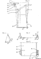
- FIGS 1, 2 and 3 show, in elevation, in plan view and in end view, a first embodiment of stirrup floor 1 adjustable size in length and its attachment to the knife 2 of the saddle 3 by an adjustable stirrup leather 4 hooked at one end on the top of a hoop 5 hinged at 6 on the front sides 7 of the floor 1.
- the hoop 5 is folded back to 8 so that the stirrup is located vertically from the knife 2.
- the pendant 9 the stirrup leather 4 is connected to a double strap 10 attached to two lateral fasteners 11 and 12 at the rear of the floor.
- the floor 1 is made of two sheet metal parts 13 and 14 each having two upwardly bent edges 7a and 7b holding the rider's boot.
- the two parts 13 and 14 are made integral with each other, for example by means of a plate 15 which can be reinforced by lateral folds and having in the longitudinal axis XX 'of the floor, a series of fixing holes 16 adjustable on the parts 13, 14 having corresponding holes, these holes can be replaced by lights making continuous size adjustment.
- the figure 3 shows an example of floor seen end, having a central double fold offset from the foot support surface, allowing the use of head screws for height adjustment without hindering the support of the foot. With this type of floor stirrup, the rider's foot is supported at the front as well as at the back. This first suspension mode of the floor stirrup does not change the pendulum movement of the stirrup relative to the knife 2.
- the figures 4 and 5 show, in top view and in elevation, a second suspension mode of a single-piece floor stirrup 20 made for example in 4 different sizes (in length and in width) and having the same fasteners as on the figure 2 .
- a front stop 22 constituted by an upward fold and an identical abutment 23 at the rear was added for the riders not using spurs.
- the floor is supported at the front by a flat hoop 21 articulated as on the figure 1 .
- the rear suspension of the floor stirrup is performed by engaging the stirrup hook 9 in an existing loop 25 on most stools, which has the effect of widening the base of the suspension of the floor stirrup. by reducing the pendulum effect occurring on the suspension of the figure 1 .
- This pendulum effect can be further reduced by further widening the seat of the suspension at the seat by removing the attachment points 25 and 2.
- the loop 25 is replaced by a U-shaped loop 27 whose ends widened 28 are pierced with a hole in which is engaged a metal rod head 29 passing through the loop of a second stirrup 26, this rod being immobilized by a small cotter pin or any other known means.
- the knife can be replaced by the same type of open loop fixed by a strap 30 sewn on the saddle.
- the figure 6 shows schematically the lateral stall of the outer strap 31 of the floor stirrup during a fall to release the foot of the rider.
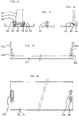
- FIGS. 7 and 8 show, end and top views, a floor stirrup 20 equipped with a spring clip 35 releasing the foot of the rider in case of a fall.
- This fastener version 35 consists of a U-bent spring steel strip each end of which has a hollow recess 36 internally in which are engaged the half-spherical end of a rod 37 on which is passed the corresponding end of the strap 10.
- the fixed fastener 38 is for example constituted by an open loop welded under the stirrup.
- FIGS 9, 10 and 11 show, from the side, from above and from the end, a floor stirrup equipped with a version of spring clip freeing the foot of the rider in the event of a fall.
- This fastener 40 consists of a downwardly bent metal rod 41, one end 42 of which is welded under the stirrup.
- the end of the strap has a hole reinforced by an eyelet engaged on the folded portion 43 of the rod which can be slightly curved.
- a leaf spring 44 attached to a portion of the angle bracket secured to the underside of the stirrup was added. The strap is held laterally in a notch 45 of the back of the stirrup.
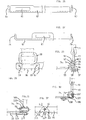
- FIGS. 12 and 13 show, in sectional and end views, a version of elastic release means of the foot of a rider mounted on the side of a floor stirrup.
- This means consists of a rod 37 receiving the corresponding end of the strap 10; the rod 37 is engaged in the indentation of a portion of bracket 48 integral with the stirrup and in the footprint of the end of a pusher 49 sliding in a block 50 pushed by a compression spring 51 itself adjustable according to the weight of the rider, by means of a screw 52 acting on the rigidity of the spring.
- the block 50 has an extension 53 which is fixed under the stirrup by means of screws 54.
- the sudden force exerted on the rod 37 causes its ends to come out of the cavities by compressing the spring 51 which release the foot.
- the rigidity of the spring 51 is adjusted by means of a tensile force gauge on the strap according to the weight of the rider.
- a plate 55 fixed under the block 50 makes the elastic release of the only lateral rear strap, which is very important at the end of show jumping to prevent the release of the strap down.
- the figure 14 shows, seen in section, an example of articulation of the arches of Figures 2, 4 and 5 whose bow portion is constituted as that of the classic stirrups.
- the hubs are pierced with a through hole of an axis 56 comprising a head, engaged in a corresponding hole of the folds 7a, 7b of the floor stirrup 20, the pins 56 being immobilized by a clip.
- the figure 15 shows, in section, a means of elastic release of a rear arch holding the back of the foot of a rider equipped with a floor stirrup.
- the arch release means is constituted by two sets of the kind of that of the figure 12 , but whose pusher 57 presses either on an imprint as on the figure 12 , or on a seat formed by a chamfer made on a hole 58 drilled in the two hubs of the hoop 59.
- FIGS 16 to 18 show, seen in section and end, a fastening means or attachment of a detachable stirrup leather, forming a sewn loop, on a floor stirrup 20, consisting of a block 62 having a housing 63 for the passage of a stirrup hook 64 or a strap clinging to a rod 65 engaged with a slight clearance in a hole drilled in the parts 66 and 67 of the block 62, the rod being immobilized after the introduction of the stirrup stirrup by means of a screw 68 squeezing on the rod.
- This clip can be fixed in various places, front and rear, of the stirrup as it will be shown on the Figures 19 to 22 , or on the side of the fold 7a, 7b as on the figure 18 .
- FIGS 19 and 20 show, viewed from the side and from above, a stirrup 75 having a floor with a front attachment 62a and a removable rear attachment 62b supported by the rear stirrups 64a and before 64b fixed on the top of the stirrup by two countersunk screws 69 or other, these two blocks 64 forming a rear stop and front stop to the boot of the rider, boot or other.
- the figure 21 shows in plan view a floor stirrup for riders carrying spurs, having a front tie 62b of stirrup hook 64b as on the figure 20 , while the rear fastener 62a is mounted on the fold 7a or 7b according to the right or left side and an elastic release back fastener, for example 76 ( Fig. 12, 13 ) mounted on the rear fold opposite to that of the fixed strap.
- FIGS 22 and 23 show, viewed from above and from the side, a floor stirrup having multiple holes for securing the various types of removable and elastically release front and back stirrup fasteners and for securing the front fastener to a position which takes into account the evolutionary size of the rider.
- a front fastener 62b it is possible to assemble on the base modular floor stirrup 80 a front fastener 62b according to the size of its foot, either at the end or at one or other of the positions shown by the drilling axes of the fixing holes.
- the rear holes allow to fix either a tie 62a as on the figure 20 , as on the figure 21 , a fastener 77 as on the Figures 24, 25 either an elastic release fastener 76, or for experienced riders a second fastener 77 or 62a.
- FIGS. 24 and 25 show a variant of attachment 77 front, rear or side fixing to a floor stirrup. It is in the form of a folded sheet having an opening with rounded edges 81 for the passage of a stirrup or double strap and two holes on its lower fold 82, fixing on the bottom or the top of the stirrup according to its location.
- FIGS. 26 and 27 show an attachment variant 85 front, rear or side 86 formed directly on a floor stirrup 87 by cutting and rounded edges to receive directly the strap and stirrup.
- FIGS. 28 and 29 show a variant of spring release hook-and-loop fastener in the event of a fall, mounted on the rear side of a floor stirrup. It comprises a ring 90 of strap 91 made prisoner against a small rounded edge 92 retaining the upper part of a plate 93 attached to the rear side 7a, 7b of the stirrup by two screws 99.
- This edge 92 has a rounded against which abuts the ring 90 held in abutment by the preformed end 94 of a leaf spring 95 and a second spring blade 96 of stiffness adjustment, according to its thickness, depending on the weight of the rider.
- the figure 30 shows a variant of a spring release hook-and-loop fastener in the event of a fall, mounted on the rear side of the floor stirrups. It comprises a groove 105 in which is engaged the strap 90 ring 91. This fastener is fixed by two screws 106 on the side 7a, 7b of the stirrup. The lateral retention of the ring 90 in its groove is ensured by a spring blade 107 fixed under the stirrup by two bolts 108.
- the Figures 31 and 32 show an example of inclination limitation stops, during jumping obstacles, floor stirrups having a hoop 109 hinged at the front on a shaft 56 engaged in the side 7a, 7b of the stirrup.
- the hub 110 comprises below, symmetrically to its vertical axis, two stops 111, 112 cooperating with a third stop 113 integral with a plate 114 fixed by screw 115 under the stirrup 20.
Landscapes
- Engineering & Computer Science (AREA)
- Mechanical Engineering (AREA)
- Seats For Vehicles (AREA)
- Footwear And Its Accessory, Manufacturing Method And Apparatuses (AREA)
- Motorcycle And Bicycle Frame (AREA)
- Braking Arrangements (AREA)
Abstract
Description
La présente invention concerne un dispositif fournissant à un cavalier des moyens accroissant considérablement son équilibre sur le cheval, notamment en position dite de sustentation.The present invention relates to a device providing a rider means considerably increasing its balance on the horse, especially in so-called lift position.
Les étriers existants présentent d'importantes insatisfactions. La longueur d'appui du pied sur les étriers existants est de l'ordre de 3 à 4 centimètres maximum. Le cavalier chausse les étriers au niveau de la partie la plus large de sa chaussure, c'est-à-dire à l'avant de son pied. Comme le centre de gravité de sa masse corporelle passe à la verticale de son talon et que cette masse s'appuie sur l'avant du pied, le cavalier se trouve en recherche permanente d'équilibre lorsqu'il se trouve en position de sustentation, tout son poids se trouvant en appui sur les étriers. Il en résulte que les étriers existants ne permettent pas au cavalier d'avoir une véritable stabilité particulièrement lors de l'apprentissage de l'équilibre à cheval. L'acquisition de la maîtrise de cet équilibre pour un cavalier, en appui sur la seule partie avant des pieds, est très difficile, très longue et reste toujours fragile, du fait que les pieds sont en permanence en bascule sur leur étrier accroché lui-même à l'extrémité d'une étrivière se comportant comme un pendule et que de plus il lui faut suivre verticalement les mouvements du cheval qui perturbent son équilibre. En outre cette recherche permanente d'équilibre est fatigante car elle engendre des contractions musculaires qui provoquent une modification des positions du cavalier préjudiciable à lui-même et au cheval.The existing stirrups present significant dissatisfaction. The length of support of the foot on the existing stirrups is of the order of 3 to 4 centimeters maximum. The rider wears the stirrups at the widest part of his shoe, that is to say at the front of his foot. As the center of gravity of his body mass passes vertically from his heel and this mass rests on the front of the foot, the rider is in constant search of balance when he is in the position of sustenance, all its weight being in support on the stirrups. As a result, the existing stirrups do not allow the rider to have a real stability especially when learning equilibrium on horseback. The acquisition of the control of this balance for a rider, bearing on the only front part of the feet, is very difficult, very long and always remains fragile, because the feet are permanently in swinging on their stirrup hooked him- even at the end of a stirrup-leaver behaving like a pendulum and moreover he must follow vertically the movements of the horse that disturb his equilibrium. In addition, this constant search for balance is tiring because it generates muscular contractions which cause a modification of the positions of the rider prejudicial to himself and the horse.
En cas de chute du cheval, il est fréquent que l'un des pieds reste accroché dans l'étrier correspondant. Il en résulte que le cavalier est traîné sur le sol par le cheval poursuivant sa course.In case of fall of the horse, it is frequent that one of the feet remains hooked in the corresponding stirrup. As a result, the rider is dragged on the ground by the horse continuing its course.
Pour pallier ces insatisfactions, les problèmes à résoudre sont les suivants :
- Réduire de façon significative le temps d'acquisition de la maîtrise de l'équilibre dynamique du cavalier en cours d'apprentissage, à toutes les allures, actuellement de l'ordre d'une année, il est nécessaire de lui fournir, au niveau de ses étriers, un appui plus stable que celui des étriers actuels pour lui permettre de maîtriser plus rapidement la composition des trois mouvements suivants: mouvements de basculement et de flexion de la cheville se produisant en permanence pour suivre les mouvements du cheval tout en conservant son équilibre dynamique ; mouvement pendulaire à partir du point d'accrochage de l'étrivière sur son couteau ; mouvement vertical pour suivre les mouvements du cheval. - Pour éviter au cavalier, après une chute du cheval, d'être traîné par celui-ci par une jambe dont le pied est resté accroché à l'étrier correspondant, le pied du cavalier doit - pouvoir se dégager automatiquement de l'étrier sous l'effort engendré par la chute.
- Significantly reduce the acquisition time of the control of the dynamic balance of the rider in the course of learning, at all speeds, currently of the order of one year, it is necessary to provide him, at the level of its calipers, a support more stable than the current calipers to allow him to control more quickly the composition of the following three movements: movements of tilting and bending of the ankle occurring continuously to follow the movements of the horse while maintaining his balance dynamic; pendulum movement from the point of attachment of the stirrup leather on his knife; vertical movement to follow the movements of the horse. - To prevent the rider, after a fall of the horse, to be dragged by it by a leg whose foot is hooked to the corresponding stirrup, the foot of the rider must - can be released automatically from the stirrup under the effort generated by the fall.
Le document
Les problèmes ainsi posés sont entièrement résolus au moyen de la selle selon l'invention. Les étriers à plancher d'appui total pour les pieds des cavaliers, leur permettent d'avoir un appui plus stable sur leur cheval. Ils comportent chacun un plancher de toute la longueur de la chaussure du cavalier, soutenu par une étrivière en partie avant et soutenu par une seconde étrivière à l'arrière.The problems thus posed are completely solved by means of the saddle according to the invention. The calipers with full support floor for the feet of the riders, allow them to have a more stable support on their horse. They each have a floor of the full length of the rider's shoe, supported by a stirrup in the front and supported by a second stirrup at the rear.
Selon un premier mode de réalisation, l'étrivière avant soutien un arceau articulé sur les côtés avants de l'étrier coopérant avec une double sangle à l'arrière. L'étrivière arrière est constituée par le pendant de l'étrivière avant passant par le couteau solidaire de la selle et soutien une double sangle fixée sur deux attaches latérales solidaires de l'arrière de l'étrier. L'étrivière avant et la double sangle arrière peuvent comporter un réglage d'inclinaison du plancher. L'étrivière avant et son pendant sont montés coulissant ou fixe sur le couteau de selle. Le pendant d'étrivière est engagé dans un passant permettant d'élargir la position de soutien de l'étrier.According to a first embodiment, the front stirrup support a hinged hoop on the front sides of the stirrup cooperating with a double strap at the rear. The rear stirrup leather is constituted by the pendant of the stirrup leather before passing through the knife integral with the saddle and supports a double strap fixed on two lateral fasteners integral with the rear of the stirrup. The front stirrup and the double back strap may include a tilt adjustment of the floor. The stirrup leather and its pendant are mounted sliding or fixed on the saddle knife. The stirrup leather pendant is engaged in a loop allowing to widen the support position of the stirrup.
Selon une variante de réalisation, l'étrivière arrière est fixée de façon amovible sur une boucle métallique en U dont les extrémités élargies sont percées d'un trou dans lequel on engage une tige métallique à tête passant dans la boucle de l'étrivière, cette tige étant immobilisée par une petite goupille fendue ou tout autre moyen connu ; la boucle en U est rendue solidaire de la selle par une lanière cousue sur celle-ci.According to an alternative embodiment, the rear stirrup is removably attached to a U-shaped metal buckle whose widened ends are pierced with a hole in which a metal rod with a passing head is engaged in the loop of the stirrup stirrup. stem being immobilized by a small cotter pin or any other known means; the U-shaped loop is secured to the saddle by a strap sewn on it.
Selon une variante de réalisation, l'étrier à plancher est constitué en deux parties munies d'une glissière de réglage de longueur en fonction de la taille dès pieds du cavalier et de côtés pliés vers le haut ainsi que des attaches d'étrivière avant et arrière.According to an alternative embodiment, the floor stirrup consists of two parts provided with a length adjustment slide according to the size of the rider's feet and folded sides upwards as well as front and back.
Selon une variante de réalisation l'étrier à plancher d'appui total est constitué d'une seule tôle comportant deux côtés pliés vers le haut et des trous de fixation des différentes attaches d'étrivière et de double sangle, ils sont de plusieurs longueurs et largeurs pour couvrir toutes les tailles.According to an alternative embodiment the caliper total support floor consists of a single sheet having two sides bent upwards and fixing holes of the different stirrup and double strap fasteners, they are of several lengths and widths to cover all sizes.
L'étrier selon l'invention comporte articulé sur ses côtés avant, un arceau et à l'arrière deux attaches latérales de la double sangle.The stirrup according to the invention comprises hinged on its front sides, a hoop and at the rear two side fasteners of the double strap.
Particulièrement pour les cavaliers débutants, l'attache arrière extérieure peut être munie d'un moyen de libération élastiquement déformable permettant à la double sangle de se dégager du côté extérieur au cheval en cas de chute.Especially for novice riders, the outer rear attachment can be provided with an elastically deformable release means allowing the double strap to be released from the outside of the horse in case of a fall.
Selon une variante de réalisation, le moyen de libération élastiquement déformable est constitué d'un ressort à lame plié en U dont chaque extrémité comporte intérieurement une empreinte en creux dans lesquelles sont engagées les extrémités demi-sphériques d'une tige sur laquelle est passée l'extrémité correspondante de la sangle.According to an alternative embodiment, the resiliently deformable release means is constituted by a U-shaped bent leaf spring, each end of which has a hollow recess internally in which are engaged the half-spherical ends of a rod on which is passed. corresponding end of the strap.
Selon une variante de réalisation, le moyen de libération élastiquement déformable est constitué d'une tige recevant l'extrémité correspondante de la sangle et est engagée dans l'empreinte en creux d'une portion d'équerre solidaire de l'étrier et dans l'empreinte de l'extrémité d'un poussoir coulissant dans un bloc poussé par un ressort de compression lui-même réglable selon le poids du cavalier, au moyen d'une vis agissant sur la rigidité du ressort, le bloc étant fixé par vis sous l'étrier.According to an alternative embodiment, the elastically deformable release means is constituted by a rod receiving the corresponding end of the strap and is engaged in the indentation of a bracket portion secured to the stirrup and in the impression of the end of a sliding pusher in a block pushed by a compression spring itself adjustable according to the weight of the rider, by means of a screw acting on the rigidity of the spring, the block being fixed by screw under stirrup.
Selon une variante de réalisation, le moyen de libération élastiquement déformable est constitué de lames de ressort agissant sur une boucle métallique de sangle pour la maintenir normalement prisonnière et coopérant avec au moins une lame de ressort complémentaire pour ajuster la rigidité du maintien de la boucle en fonction du poids du cavalier.According to an alternative embodiment, the elastically deformable release means consists of spring blades acting on a metal strap buckle to maintain it normally trapped and cooperating with at least one complementary leaf spring to adjust the rigidity of the maintenance of the buckle. according to the weight of the rider.
Selon une variante de réalisation, le moyen de libération élastiquement déformable est constitué d'une tige métallique pliée vers le bas dont une extrémité est soudée sous l'étrier, l'extrémité de la sangle comporte un trou renforcé par un oeillet engagé sur la partie pliée de la tige qui peut être légèrement courbée et est maintenu par un ressort à lame fixé sur une portion de cornière solidaire du dessous de l'étrier.According to an alternative embodiment, the elastically deformable release means consists of a downwardly bent metal rod, one end of which is welded under the stirrup, the end of the strap comprises a hole reinforced by an eyelet engaged on the part bent of the rod which can be slightly curved and is held by a leaf spring fixed to a portion of bracket integrally underneath the stirrup.
Selon une variante de réalisation, l'étrivière arrière est rendue solidaire d'un arceau articulé sur un moyen à libération élastiquement déformable à poussoir à ressort et coopérant à l'avant dudit étrier avec un autre arceau articulé.According to an alternative embodiment, the rear stirrup is secured to a hinged hoop on an elastically deformable release means spring loaded and cooperating in the front of said stirrup with another hinged hoop.
Selon une variante de réalisation, qui ne fait pas partie de la présente invention attaches amovibles d'étrivière et sangle sont constituées d'un bloc comportant un logement de passage d'une étrivière ou d'une sangle s'accrochant sur une tige engagée avec un léger jeu dans un trou percé dans les parties du bloc, la tige étant immobilisée sur le bloc après la mise en place de l'étrivière.According to an alternative embodiment, which is not part of the present invention removable stirrup stirrups and strap consist of a block having a passage housing of a stirrup or stirrup strap hanging on a rod engaged with a slight play in a hole drilled in the parts of the block, the rod being immobilized on the block after the establishment of the stirrup leather.
Selon une variante de réalisation, les attaches d'étrivière et sangle avant, arrière ou latérale se fixant sur ledit étrier à plancher se présentent sous forme d'une tôle pliée comportant une ouverture à bords arrondis pour le passage d'une étrivière ou d'une double sangle et de deux trous sur son pli inférieur, de fixation sur le dessous ou le dessus de l'étrier selon son emplacement sur celui-ci.According to an alternative embodiment, the stirrup and strap fasteners front, rear or lateral attaching to said stirrup floor are in the form of a folded sheet having an opening with rounded edges for the passage of a stirrup or stirrup a double strap and two holes on its lower fold, fixing on the bottom or the top of the stirrup according to its location on it.
Selon une variante de réalisation qui ne fait pas partie de la présente invention, les attaches d'étrivière et sangle avant et arrière ou latérales sont ménagées directement sur un étrier à plancher par découpe et bords arrondis pour recevoir directement lesdites sangle et étrivière.According to an alternative embodiment which is not part of the present invention, the stirrup and strap fasteners front and rear or side are formed directly on a floor stirrup cut and rounded edges to receive directly said strap and stirrup.
La selle peut être équipée de deux paires de couteaux écartées pour recevoir les étrivières avant et arrière.The saddle can be equipped with two pairs of knives separated to receive the stirrups front and back.
Selon une variante qui ne fait pas partie de la présente invention, l'équipement dudit étrier comporte une attache amovible à l'avant et à l'arrière.According to a variant which does not form part of the present invention, the equipment of said stirrup comprises a removable fastener at the front and at the rear.
Selon une variante dudit étrier, qui ne fait pas partie de la présente invention, il comporte une attache amovible à l'avant et une seconde attache latérale à l'arrière coopérant avec une attache à libération élastiquement déformable.According to a variant of said caliper, which does not form part of the present invention, it comprises a removable attachment at the front and a second lateral attachment at the rear cooperating with an elastically deformable release fastener.
Selon une variante dudit étrier il comporte des perçages multiples permettant de fixer divers types d'attaches d'étrivières avant et arrière amovibles et à libération élastique et de fixer l'attache avant d'étrivière tenant compte de la taille évolutive du cavalier.According to a variant of said stirrup it has multiple holes for fixing various types of removable and elastic release front and rear stirrup fasteners and attaching the stirrup front fastener taking into account the scalable size of the rider.
Les avantages apportés par l'ensemble étrier-selle selon l'invention sont les suivants :
- Les étriers à appui avant et arrière du pied offrent une excellente stabilité au cavalier à toutes les allures lorsque la totalité de son poids repose sur les étriers en position de sustentation ; il en résulte que, pour les débutants, le temps d'apprentissage de la maîtrise de l'équilibre en sustentation, d'environ une année, se trouve réduit à quelques heures seulement ; il ne reste plus alors au cavalier qu'à apprendre à « pomper » autour d'une position moyenne pour suivre les mouvement de son cheval avec une fatigue très réduite puisqu'il n'a plus à assurer simultanément son équilibre.
- En cas de chute, le pied du cavalier se trouve libéré de l'étrier et il ne risque plus d'être traîné par son cheval.
- Pour les handicapés, ils offrent confort et sécurité.
- Dans les disciplines de l'endurance, du saut d'obstacles, du cross, des courses de trot, ils permettent d'optimiser les performances.
- Pour le tourisme équestre ils améliorent considérablement le confort et la sécurité tout en réduisant la fatigue.
- Ils permettent une meilleure répartition du poids du cavalier sur le dos du cheval, d'où il résulte une meilleure locomotion de celui-ci.
- The front and rear support brackets of the foot provide excellent stability to the rider at all speeds when his entire weight rests on the stirrups in lift position; as a result, for beginners, the learning time of the control of the equilibrium in lift, of about a year, is reduced to only a few hours; the only thing left for the rider to do is to learn to "pump" around an average position to follow the movement of his horse with a very reduced fatigue since he no longer has to maintain his balance at the same time.
- In the event of a fall, the rider's foot is released from the stirrup and he is no longer likely to be dragged by his horse.
- For the disabled, they offer comfort and security.
- In the disciplines of endurance, jumping, cross country, trotting races, they can optimize performance.
- For equestrian tourism they greatly improve comfort and safety while reducing fatigue.
- They allow a better distribution of the weight of the rider on the horse's back, from where it results a better locomotion of this one.
L'invention sera mieux comprise à la lecture de la description qui suit, faite en regard des figures présentées à titre non limitatif de l'invention, dans lesquelles :
- les
figures 1, 2 et 3 montrent, en élévation et en vue de dessus et en vue en bout, un premier mode de réalisation d'étrier à plancher et son accrochage à la selle selon l'invention, à taille réglable en longueur ; - la
figure 4 montre un second mode de réalisation d'un étrier à plancher en une seule partie; - la
figure 5 montre un second mode d'accrochage de l'étrier à plancher sur une selle ; - la
figure 6 montre schématiquement le décrochage latéral de la sangle extérieur de l'étrier à plancher au cours d'une chute pour libérer le pied du cavalier ; - les
figures 7 et 8 montrent, vues en bout et de dessus, un étrier à plancher équipé d'une attache à ressort libérant le pied du cavalier en cas de chute ; - les
figures 9, 10 et 11 montrent, vues de côté, de dessus et en bout, un étrier à plancher équipé d'une attache à ressort libérant le pied du cavalier en cas de chute ; - les
figures 12 et 13 montrent, vues en coupe et en bout, un moyen de libération élastique du pied d'un cavalier monté sur le côté d'un étrier à plancher ; - les
figures 14 et 15 montrent, vues en coupe, un moyen de libération élastique d'un arceau arrière maintenant l'arrière du pied d'un cavalier équipé d'un étrier à plancher ; - les
figures 16 à 18 montrent, vues en coupe et en bout, un moyen de fixation d'une étrivière amovible sur un étrier à plancher qui ne fait pas partie de la présente invention ; - les
figures 19 et 20 montrent, vues de côté et de dessus, un mode d'étrier à plancher, qui ne fait pas partie de présente invention, comportant une attache avant et une attache arrière amovibles; - la
figure 21 montre en vue de dessus un mode de réalisation d'étrier à plancher, qui ne fait pas partie de la présente invention, comportant une attache avant d'étrivière, une attache arrière gauche et une attache arrière droite à libération élastique ; - les
figures 22 et 23 montrent, vues de côté et de dessus, un mode d'étrier à plancher, où la variante de lafigure 22 ne fait pas partie de la présente invention, comportant des perçages multiples permettant de fixer divers types d'attaches d'étrivières avant et arrière amovibles et à libération élastique et de fixer l'attache avant en fonction de la taille du cavalier ; - les
figures 24 et 25 montrent une variante d'attache avant, arrière ou latérale se fixant sur un étrier à plancher ; - les
figures 26 et 27 montrent une variante d'attache avant, arrière ou latérale ménagées directement sur un étrier à plancher, qui ne fait pas partie de la présente invention ; - les
figures 28 et 29 montrent une variante d'attache de boucle d'étrivière à libération élastique en cas de chute, se montant sur le côté arrière d'un étrier à plancher ; - la
figure 30 montre une variante d'attache de boucle d'étrivière à libération élastique en cas de chute, se montant sur le côté arrière d'un étrier à plancher. - les
figures 31 et 32 montrent un exemple de butées de limitation d'inclinaison de l'étrier en cours de saut d'obstacle.
- the
Figures 1, 2 and 3 show, in elevation and in plan view and in end view, a first embodiment of stirrup floor and its attachment to the saddle according to the invention, with size adjustable in length; - the
figure 4 shows a second embodiment of a single-piece floor stirrup; - the
figure 5 shows a second mode of attachment of the floor stirrup on a saddle; - the
figure 6 schematically shows the lateral stall of the outside strap of the floor stirrup during a fall to release the foot of the rider; - the
Figures 7 and 8 show, viewed from the end and from above, a floor stirrup equipped with a spring clip freeing the rider's foot in the event of a fall; - the
Figures 9, 10 and 11 show, from the side, from above and from the end, a floor stirrup equipped with a spring clip freeing the rider's foot in the event of a fall; - the
Figures 12 and 13 show, in sectional and end views, an elastic release means of the foot of a rider mounted on the side of a floor stirrup; - the
Figures 14 and 15 show, in sectional view, an elastic release means of a rear arch holding the rear of the foot of a rider equipped with a floor stirrup; - the
Figures 16 to 18 show, seen in section and end, a fastening means of a removable stirrup on a floor stirrup which is not part of the present invention; - the
Figures 19 and 20 show, from the side and from above, a floor stirrup mode, which is not part of the present invention, having a removable front attachment and a rear attachment; - the
figure 21 shows in plan view an embodiment of a floor stirrup, which is not part of the present invention, comprising a stirrup front fastener, a left rear fastener and a right elastic release back fastener; - the
Figures 22 and 23 show, seen from the side and from above, a floor stirrup mode, where the variant of thefigure 22 is not part of the present invention, having multiple bores for attaching various types of removable and elastic release front and back stirrups and attaching the front attachment depending on the size of the rider; - the
Figures 24 and 25 show a front, rear or side attachment variant attaching to a floor stirrup; - the
Figures 26 and 27 show an alternative front, rear or side attachment formed directly on a floor stirrup, which is not part of the present invention; - the
Figures 28 and 29 show a variant of spring release hook-and-loop fastener in the event of a fall, mounted on the rear side of a floor stirrup; - the
figure 30 shows a variant of a spring release hook-and-loop fastener in the event of a fall, mounted on the rear side of a floor stirrup. - the
Figures 31 and 32 show an example of stops of inclination limitation of the stirrup during jumping.
Les
Les
Cette assise plus large de la suspension de l'étrier améliore l'équilibre des débutants.This wider seat of the stirrup suspension improves the balance of beginners.
La
Les
Les
Les
La
Les moyeux sont percés d'un trou de passage d'un axe 56 comportant une tête, engagé dans un trou correspondant des plis 7a, 7b de l'étrier à plancher 20, les axes 56 étant immobilisé par un clip.The hubs are pierced with a through hole of an
La
Le moyen de libération de l'arceau est constitué par deux ensembles du genre de celui de la
Les
Les
La
Les
Les
Les
Les
La
Les
Claims (17)
- A saddle (3) on which is assembled a stirrup with a totally supporting base for a foot of a rider, allowing the rider to be supported on his/her horse, said stirrup including a front and rear supporting base (1, 20) for the foot, a first stirrup leather (4) in the front portion of the stirrup, a second stirrup leather (9, 26) at the rear of the stirrup, said stirrup being characterized in that said first stirrup leather (4) is hung on a cradle (5, 21) jointed on the sides (7a, 7b) of the base (1, 20) at the front of the stirrup, in that the stirrup at the rear comprises a double strap (10) attached onto two side ties (35, 38), firmly attached to the rear of the stirrup, the double strap (10) being supported by the second stirrup leather (9, 26), and in that the first and the second stirrup leather are attached onto the saddle, either at a single fastening point (2) or at respective front (2) and rear (25, 27) fittings spaced apart from each other.
- The saddle according to claim 1, characterized in that the rear stirrup leather (9) is formed by the hanging part of the first stirrup leather (4) passing through the sole fastening point, i.e. a bar (2) firmly attached to the saddle.
- The saddle according to claim 1 or 2, characterized in that the first stirrup leather (4) and the double strap (10) include an adjustment for the inclination of the base.
- The saddle according to one of the preceding claims, characterized in that the first stirrup leather (4) and its hanging part (9) are slideably or fixedly mounted on the bar (2).
- The saddle according to one of the preceding claims, characterized in that the rear stirrup leather (26) is removably attached on a U-shaped loop (27), the widened ends (28) of which are pierced with a hole, into which is engaged a metal rod with a head (29) passing into the sewn_loop of the stirrup leather (26), this rod being immobilized by a small slit pin or any other know means, in that the U-shaped loop (27) is made interdependent of the saddle through a thong (30) sewn on the latter.
- The saddle according to one of the preceding claims, characterized in that the stirrup base consists of two portions (13, 14), provided with a slider for adjusting the length depending on the size of the feet of the rider and with sides folded upwards (7a, 7b) as well as on the front and rear stirrup leather ties.
- The saddle according to one of claims 1 to 5, characterized in that the base consists of a metal sheet (20) including two sides folded upwards (7a, 7b) and of the holes for attaching the different stirrup leather and double strap ties.
- The saddle according to claim 6, characterized in that each outer rear tie is provided with an elastically deformable releasing means allowing the double strap to be disengaged from the outer side to the horse in the case of a fall.
- The saddle according to claim 8, characterized in that the elastically deformable releasing means consists of a leaf spring folded as a U, each end of which interiorly includes a recessed imprint (36), into which are engaged hemispherical ends of a rod (37) on which is passed the corresponding end of the strap (10).
- The saddle according to claim 8, characterized in that the elastically deformable releasing means consists of a rod (37) receiving the corresponding end of the strap (10), engaged into the recessed imprint of a square portion (48) firmly attached to the stirrup and into the imprint of the end of a pusher (49) sliding in a block (50) pushed by a compression spring (51) itself adjustable according to the weight of the rider, by means of a screw (52) acting on the stiffness of said spring, in that the block (50) is attached by screws under the stirrup (20).
- The saddle according to claim 8, characterized in that the elastically deformable releasing means consists of a spring leaf (95) acting on a strap (91) metal loop (90) in order to maintain it normally confined and cooperating with at least one additional spring leaf (96) for adjusting the stiffness of the hold of the loop according to the weight of the rider.
- The saddle according to claim 8, characterized in that the elastically deformable releasing means is a strap tie including a groove (105), into which is engaged a strap (91) ring (90), in that it is attached by two screws (106) on the rear side (7a, 7b) of the stirrup, in that the lateral hold of the ring (90) in its groove is ensured by a spring leaf (107) attached under the stirrup by two bolts (108).
- The saddle according to claim 8, characterized in that the elastically deformable releasing means consists of a metal rod folded downwards (41), one end (42) of which is welded under the stirrup, the end of the strap includes a hole reinforced by an eyelet engaged on the folded portion (43) of the rod, which may be slightly bent, and is maintained by a spring leaf (44) attached on a corner iron portion firmly attached to the bottom of the stirrup.
- The saddle according to claim 1, characterized in that the second stirrup leather (9, 26) is secured to an arch (59) hinged on an elastically deformable releasing means with a pusher (57), with a spring (51) and adjustment screw (52), and cooperating with another hinged arch in the front of said stirrup.
- The saddle according to claim 1, characterized in that the front, rear or side strap and stirrup leather ties (77) are attached on said stirrup with a base (20) appearing as a folded metal sheet, including an opening with rounded edges (81) for letting through a stirrup leather or a double strap and two holes on its lower fold (82) for attachment on the underneath or the top of the stirrup depending on its location on the latter.
- The saddle according to claim 5, characterized in that it is equipped with two pairs of bars (2) spaced apart in order to receive the front (4) and rear (26) stirrup leathers.
- The saddle according to any of claims 1, 8 to 13 and 15, characterized in that the stirrup is provided at the front with means for limiting the inclination of the base during show jumping, including a hinged arch (109) at the front on two axes (56) engaged into the side (7a, 7b) of the stirrup, the hubs (110) of which bear underneath, symmetrically to their vertical axis, two abutments (111, 112) cooperating with a third abutment (113) firmly attached to a plate (114) attached with screws (115) under the stirrup (20).
Applications Claiming Priority (1)
| Application Number | Priority Date | Filing Date | Title |
|---|---|---|---|
| PCT/FR2005/000617 WO2006097581A1 (en) | 2005-03-15 | 2005-03-15 | Stirrups with total support floor for riders' feet |
Publications (2)
| Publication Number | Publication Date |
|---|---|
| EP2016021A1 EP2016021A1 (en) | 2009-01-21 |
| EP2016021B1 true EP2016021B1 (en) | 2012-05-02 |
Family
ID=35385489
Family Applications (1)
| Application Number | Title | Priority Date | Filing Date |
|---|---|---|---|
| EP05739508A Not-in-force EP2016021B1 (en) | 2005-03-15 | 2005-03-15 | Stirrups with total support floor for riders' feet |
Country Status (5)
| Country | Link |
|---|---|
| US (1) | US20080047237A1 (en) |
| EP (1) | EP2016021B1 (en) |
| AT (1) | ATE556027T1 (en) |
| CA (1) | CA2594972A1 (en) |
| WO (1) | WO2006097581A1 (en) |
Families Citing this family (6)
| Publication number | Priority date | Publication date | Assignee | Title |
|---|---|---|---|---|
| US20090044499A1 (en) * | 2007-07-02 | 2009-02-19 | Sara Chambers | Riding stirrup |
| FR2934255B1 (en) * | 2008-07-25 | 2011-03-25 | Gaston Mercier Dev Soc | DEVICE FOR SUSPENDING BY A BELT TO A SADDLE, FOR SERVING A FOOT OF A RIDER, OF THE TYPE OF RIDING CALIPER |
| NO344417B1 (en) * | 2018-01-05 | 2019-12-02 | Maria Terese Engell | Stirrup and combination of stirrup and a leather |
| US11629045B2 (en) | 2019-05-20 | 2023-04-18 | Michel Cabiran | Stirrup and method of using the same |
| US11161732B2 (en) | 2019-05-20 | 2021-11-02 | Michel Cabiran | Stirrup and method of using the same |
| FR3108111B1 (en) * | 2020-03-16 | 2022-03-04 | Jacques Bardies | Stirrup height adjustment device on horse-riding saddles by pulley and cam cleat |
Citations (1)
| Publication number | Priority date | Publication date | Assignee | Title |
|---|---|---|---|---|
| GB191104156A (en) * | 1911-02-18 | 1911-05-11 | Pierre Wenner | Improvements in Stirrups. |
Family Cites Families (10)
| Publication number | Priority date | Publication date | Assignee | Title |
|---|---|---|---|---|
| US569071A (en) * | 1896-10-06 | Saddle-stirrup | ||
| US95857A (en) * | 1869-10-12 | Improved stirrup | ||
| US112652A (en) * | 1871-03-14 | Improvement in stirrups for riding-saddles | ||
| US469153A (en) * | 1892-02-16 | Saddle-stirrup | ||
| US872264A (en) * | 1907-01-22 | 1907-11-26 | Jacob Tweit | Stirrup. |
| US949830A (en) * | 1909-04-03 | 1910-02-22 | John Gore Massie | Safety-stirrup. |
| US985346A (en) * | 1910-06-04 | 1911-02-28 | John R Hunter | Safety-stirrup. |
| US1028763A (en) * | 1910-08-05 | 1912-06-04 | John C Miller | Stirrup. |
| FR2616141A1 (en) | 1987-06-05 | 1988-12-09 | Voland Frederic | Stirrup with longitudinal support and automatic balancing of the foot with adapted saddle |
| US7096652B2 (en) * | 2002-12-06 | 2006-08-29 | Milinda Hendrick Kirkpatrick | Riding pad for two persons |
-
2005
- 2005-03-15 US US11/814,026 patent/US20080047237A1/en not_active Abandoned
- 2005-03-15 EP EP05739508A patent/EP2016021B1/en not_active Not-in-force
- 2005-03-15 WO PCT/FR2005/000617 patent/WO2006097581A1/en not_active Application Discontinuation
- 2005-03-15 AT AT05739508T patent/ATE556027T1/en active
- 2005-03-15 CA CA002594972A patent/CA2594972A1/en not_active Abandoned
Patent Citations (1)
| Publication number | Priority date | Publication date | Assignee | Title |
|---|---|---|---|---|
| GB191104156A (en) * | 1911-02-18 | 1911-05-11 | Pierre Wenner | Improvements in Stirrups. |
Also Published As
| Publication number | Publication date |
|---|---|
| EP2016021A1 (en) | 2009-01-21 |
| US20080047237A1 (en) | 2008-02-28 |
| CA2594972A1 (en) | 2006-09-21 |
| WO2006097581A1 (en) | 2006-09-21 |
| ATE556027T1 (en) | 2012-05-15 |
Similar Documents
| Publication | Publication Date | Title |
|---|---|---|
| EP2016021B1 (en) | Stirrups with total support floor for riders' feet | |
| JP4920600B2 (en) | Winter recreation equipment | |
| FR2556687A1 (en) | DEVICE FOR FIXING A SHOE ON A BICYCLE PEDAL | |
| FR2752528A1 (en) | DEVICE FOR FIXING THE FOOT ON A SPORTS MACHINE, OF THE SNOW SURFBOARD, SKATEBOARD OR SKATE TYPE, COMPOSED OF A BOOT AND A BASE ATTACHED TO THE SPORTS MACHINE | |
| EP2699323B1 (en) | Assistance system for a gliding board or snowshoe | |
| EP1478592B1 (en) | Stirrup with automatic fixing | |
| FR2896761A1 (en) | BICYCLE SADDLE WITH TWO SEATS | |
| EP0940160B1 (en) | Snow sport device | |
| FR3027892A1 (en) | REMOVABLE SYSTEM FACILITATING THE ADJUSTMENT OF A BEELLE DE BEELLE CALIPER | |
| FR2645037A1 (en) | Device for fastening a pair of boots of a skier on a board for sliding over snow, such as a snowboard or a monoski | |
| FR2616141A1 (en) | Stirrup with longitudinal support and automatic balancing of the foot with adapted saddle | |
| EP0348391A1 (en) | Ski and safety binding assembly | |
| EP3962801B1 (en) | Footrest with adjustable bearing point | |
| FR2740350A1 (en) | SPECIFIC MOUNTING FOR A SLIDING MACHINE CONSISTING OF A SINGLE BOARD, AND MACHINE PROVIDED WITH SUCH MOUNTING | |
| FR2644129A1 (en) | Flexible device for fixing a shoe to a bicycle pedal | |
| FR2888513A1 (en) | DEVICE FOR MOVING ON SNOW OR ICE | |
| FR3046938A1 (en) | RESTRAINT DEVICE FOR MULTIPURPOSE SKI WITH DEBRAYABLE FASTENING AND SKI SHOE SUITABLE FOR SUCH A SKI. | |
| CA2127159C (en) | Ice cycle | |
| FR3027299A1 (en) | EQUITATION SADDLE EQUIPPED WITH AT LEAST ONE ADJUSTABLE HEIGHT | |
| US382690A (en) | Thomas coady | |
| FR2789985A1 (en) | RIDING ACCESSORY, FIXED TO THE HANGER, WITH PEDAGOGICAL FUNCTION, COMFORT AND SAFETY | |
| FR2861065A1 (en) | Horse rider stabilizing device, has floor board supported on its rear portion by double foot strap, safety valve permitting disengagement of strap, and two guide rails and two screws for adjusting length of board | |
| FR3084253A1 (en) | ORTHOPEDIC DAMBULATION ASSISTANCE DEVICE FOR WALKING REHABILITATION | |
| FR2657270A1 (en) | Binding (fastening) assembly for a sliding board such as a monoski or a snowboard | |
| FR2815878A1 (en) | Ski binding for downhill ski comprises pivot, on to which boot is fixed, and whose lower end is attached to springs acting in opposite directions whose far ends are mounted in perforated plates, allowing their positions to be adjusted |
Legal Events
| Date | Code | Title | Description |
|---|---|---|---|
| PUAI | Public reference made under article 153(3) epc to a published international application that has entered the european phase |
Free format text: ORIGINAL CODE: 0009012 |
|
| 17P | Request for examination filed |
Effective date: 20070706 |
|
| AK | Designated contracting states |
Kind code of ref document: A1 Designated state(s): AT BE BG CH CY CZ DE DK EE ES FI FR GB GR HU IE IS IT LI LT LU MC NL PL PT RO SE SI SK TR |
|
| 17Q | First examination report despatched |
Effective date: 20110308 |
|
| GRAP | Despatch of communication of intention to grant a patent |
Free format text: ORIGINAL CODE: EPIDOSNIGR1 |
|
| GRAS | Grant fee paid |
Free format text: ORIGINAL CODE: EPIDOSNIGR3 |
|
| GRAA | (expected) grant |
Free format text: ORIGINAL CODE: 0009210 |
|
| AK | Designated contracting states |
Kind code of ref document: B1 Designated state(s): AT BE BG CH CY CZ DE DK EE ES FI FR GB GR HU IE IS IT LI LT LU MC NL PL PT RO SE SI SK TR |
|
| REG | Reference to a national code |
Ref country code: GB Ref legal event code: FG4D Free format text: NOT ENGLISH |
|
| REG | Reference to a national code |
Ref country code: CH Ref legal event code: EP Ref country code: AT Ref legal event code: REF Ref document number: 556027 Country of ref document: AT Kind code of ref document: T Effective date: 20120515 |
|
| REG | Reference to a national code |
Ref country code: IE Ref legal event code: FG4D Free format text: LANGUAGE OF EP DOCUMENT: FRENCH |
|
| REG | Reference to a national code |
Ref country code: DE Ref legal event code: R096 Ref document number: 602005033992 Country of ref document: DE Effective date: 20120705 |
|
| RAP2 | Party data changed (patent owner data changed or rights of a patent transferred) |
Owner name: POUGNARD, EMMANUELLE Owner name: LANTUEJOUL, LAURENT |
|
| RIN2 | Information on inventor provided after grant (corrected) |
Inventor name: LANTUEJOUL, LAURENT Inventor name: POUGNARD, EMMANUELLE |
|
| REG | Reference to a national code |
Ref country code: NL Ref legal event code: VDEP Effective date: 20120502 |
|
| REG | Reference to a national code |
Ref country code: LT Ref legal event code: MG4D Effective date: 20120502 |
|
| PG25 | Lapsed in a contracting state [announced via postgrant information from national office to epo] |
Ref country code: PL Free format text: LAPSE BECAUSE OF FAILURE TO SUBMIT A TRANSLATION OF THE DESCRIPTION OR TO PAY THE FEE WITHIN THE PRESCRIBED TIME-LIMIT Effective date: 20120502 Ref country code: SE Free format text: LAPSE BECAUSE OF FAILURE TO SUBMIT A TRANSLATION OF THE DESCRIPTION OR TO PAY THE FEE WITHIN THE PRESCRIBED TIME-LIMIT Effective date: 20120502 Ref country code: LT Free format text: LAPSE BECAUSE OF FAILURE TO SUBMIT A TRANSLATION OF THE DESCRIPTION OR TO PAY THE FEE WITHIN THE PRESCRIBED TIME-LIMIT Effective date: 20120502 Ref country code: FI Free format text: LAPSE BECAUSE OF FAILURE TO SUBMIT A TRANSLATION OF THE DESCRIPTION OR TO PAY THE FEE WITHIN THE PRESCRIBED TIME-LIMIT Effective date: 20120502 Ref country code: IS Free format text: LAPSE BECAUSE OF FAILURE TO SUBMIT A TRANSLATION OF THE DESCRIPTION OR TO PAY THE FEE WITHIN THE PRESCRIBED TIME-LIMIT Effective date: 20120902 Ref country code: CY Free format text: LAPSE BECAUSE OF FAILURE TO SUBMIT A TRANSLATION OF THE DESCRIPTION OR TO PAY THE FEE WITHIN THE PRESCRIBED TIME-LIMIT Effective date: 20120502 |
|
| REG | Reference to a national code |
Ref country code: AT Ref legal event code: MK05 Ref document number: 556027 Country of ref document: AT Kind code of ref document: T Effective date: 20120502 |
|
| PG25 | Lapsed in a contracting state [announced via postgrant information from national office to epo] |
Ref country code: PT Free format text: LAPSE BECAUSE OF FAILURE TO SUBMIT A TRANSLATION OF THE DESCRIPTION OR TO PAY THE FEE WITHIN THE PRESCRIBED TIME-LIMIT Effective date: 20120903 Ref country code: SI Free format text: LAPSE BECAUSE OF FAILURE TO SUBMIT A TRANSLATION OF THE DESCRIPTION OR TO PAY THE FEE WITHIN THE PRESCRIBED TIME-LIMIT Effective date: 20120502 Ref country code: GR Free format text: LAPSE BECAUSE OF FAILURE TO SUBMIT A TRANSLATION OF THE DESCRIPTION OR TO PAY THE FEE WITHIN THE PRESCRIBED TIME-LIMIT Effective date: 20120803 |
|
| PG25 | Lapsed in a contracting state [announced via postgrant information from national office to epo] |
Ref country code: SK Free format text: LAPSE BECAUSE OF FAILURE TO SUBMIT A TRANSLATION OF THE DESCRIPTION OR TO PAY THE FEE WITHIN THE PRESCRIBED TIME-LIMIT Effective date: 20120502 Ref country code: AT Free format text: LAPSE BECAUSE OF FAILURE TO SUBMIT A TRANSLATION OF THE DESCRIPTION OR TO PAY THE FEE WITHIN THE PRESCRIBED TIME-LIMIT Effective date: 20120502 Ref country code: RO Free format text: LAPSE BECAUSE OF FAILURE TO SUBMIT A TRANSLATION OF THE DESCRIPTION OR TO PAY THE FEE WITHIN THE PRESCRIBED TIME-LIMIT Effective date: 20120502 Ref country code: DK Free format text: LAPSE BECAUSE OF FAILURE TO SUBMIT A TRANSLATION OF THE DESCRIPTION OR TO PAY THE FEE WITHIN THE PRESCRIBED TIME-LIMIT Effective date: 20120502 Ref country code: EE Free format text: LAPSE BECAUSE OF FAILURE TO SUBMIT A TRANSLATION OF THE DESCRIPTION OR TO PAY THE FEE WITHIN THE PRESCRIBED TIME-LIMIT Effective date: 20120502 Ref country code: CZ Free format text: LAPSE BECAUSE OF FAILURE TO SUBMIT A TRANSLATION OF THE DESCRIPTION OR TO PAY THE FEE WITHIN THE PRESCRIBED TIME-LIMIT Effective date: 20120502 Ref country code: NL Free format text: LAPSE BECAUSE OF FAILURE TO SUBMIT A TRANSLATION OF THE DESCRIPTION OR TO PAY THE FEE WITHIN THE PRESCRIBED TIME-LIMIT Effective date: 20120502 |
|
| PG25 | Lapsed in a contracting state [announced via postgrant information from national office to epo] |
Ref country code: IT Free format text: LAPSE BECAUSE OF FAILURE TO SUBMIT A TRANSLATION OF THE DESCRIPTION OR TO PAY THE FEE WITHIN THE PRESCRIBED TIME-LIMIT Effective date: 20120502 |
|
| PLBE | No opposition filed within time limit |
Free format text: ORIGINAL CODE: 0009261 |
|
| STAA | Information on the status of an ep patent application or granted ep patent |
Free format text: STATUS: NO OPPOSITION FILED WITHIN TIME LIMIT |
|
| 26N | No opposition filed |
Effective date: 20130205 |
|
| PG25 | Lapsed in a contracting state [announced via postgrant information from national office to epo] |
Ref country code: ES Free format text: LAPSE BECAUSE OF FAILURE TO SUBMIT A TRANSLATION OF THE DESCRIPTION OR TO PAY THE FEE WITHIN THE PRESCRIBED TIME-LIMIT Effective date: 20120813 |
|
| REG | Reference to a national code |
Ref country code: DE Ref legal event code: R097 Ref document number: 602005033992 Country of ref document: DE Effective date: 20130205 |
|
| PG25 | Lapsed in a contracting state [announced via postgrant information from national office to epo] |
Ref country code: BG Free format text: LAPSE BECAUSE OF FAILURE TO SUBMIT A TRANSLATION OF THE DESCRIPTION OR TO PAY THE FEE WITHIN THE PRESCRIBED TIME-LIMIT Effective date: 20120802 |
|
| BERE | Be: lapsed |
Owner name: LANTUEJOUL, LAURENT Effective date: 20130331 |
|
| PG25 | Lapsed in a contracting state [announced via postgrant information from national office to epo] |
Ref country code: MC Free format text: LAPSE BECAUSE OF NON-PAYMENT OF DUE FEES Effective date: 20130331 |
|
| REG | Reference to a national code |
Ref country code: CH Ref legal event code: PL |
|
| REG | Reference to a national code |
Ref country code: IE Ref legal event code: MM4A |
|
| PG25 | Lapsed in a contracting state [announced via postgrant information from national office to epo] |
Ref country code: CH Free format text: LAPSE BECAUSE OF NON-PAYMENT OF DUE FEES Effective date: 20130331 Ref country code: BE Free format text: LAPSE BECAUSE OF NON-PAYMENT OF DUE FEES Effective date: 20130331 Ref country code: LI Free format text: LAPSE BECAUSE OF NON-PAYMENT OF DUE FEES Effective date: 20130331 Ref country code: IE Free format text: LAPSE BECAUSE OF NON-PAYMENT OF DUE FEES Effective date: 20130315 |
|
| PG25 | Lapsed in a contracting state [announced via postgrant information from national office to epo] |
Ref country code: TR Free format text: LAPSE BECAUSE OF FAILURE TO SUBMIT A TRANSLATION OF THE DESCRIPTION OR TO PAY THE FEE WITHIN THE PRESCRIBED TIME-LIMIT Effective date: 20120502 |
|
| PG25 | Lapsed in a contracting state [announced via postgrant information from national office to epo] |
Ref country code: HU Free format text: LAPSE BECAUSE OF FAILURE TO SUBMIT A TRANSLATION OF THE DESCRIPTION OR TO PAY THE FEE WITHIN THE PRESCRIBED TIME-LIMIT; INVALID AB INITIO Effective date: 20050315 Ref country code: LU Free format text: LAPSE BECAUSE OF NON-PAYMENT OF DUE FEES Effective date: 20130315 |
|
| REG | Reference to a national code |
Ref country code: FR Ref legal event code: PLFP Year of fee payment: 12 |
|
| PGFP | Annual fee paid to national office [announced via postgrant information from national office to epo] |
Ref country code: FR Payment date: 20160331 Year of fee payment: 12 |
|
| PGFP | Annual fee paid to national office [announced via postgrant information from national office to epo] |
Ref country code: DE Payment date: 20160413 Year of fee payment: 12 Ref country code: GB Payment date: 20160418 Year of fee payment: 12 |
|
| REG | Reference to a national code |
Ref country code: DE Ref legal event code: R119 Ref document number: 602005033992 Country of ref document: DE |
|
| GBPC | Gb: european patent ceased through non-payment of renewal fee |
Effective date: 20170315 |
|
| REG | Reference to a national code |
Ref country code: FR Ref legal event code: ST Effective date: 20171130 |
|
| PG25 | Lapsed in a contracting state [announced via postgrant information from national office to epo] |
Ref country code: DE Free format text: LAPSE BECAUSE OF NON-PAYMENT OF DUE FEES Effective date: 20171003 Ref country code: FR Free format text: LAPSE BECAUSE OF NON-PAYMENT OF DUE FEES Effective date: 20170331 |
|
| PG25 | Lapsed in a contracting state [announced via postgrant information from national office to epo] |
Ref country code: GB Free format text: LAPSE BECAUSE OF NON-PAYMENT OF DUE FEES Effective date: 20170315 |