EP2015563B1 - Bildaufnahmevorrichtung und Steuerverfahren dafür - Google Patents
Bildaufnahmevorrichtung und Steuerverfahren dafür Download PDFInfo
- Publication number
- EP2015563B1 EP2015563B1 EP08157682A EP08157682A EP2015563B1 EP 2015563 B1 EP2015563 B1 EP 2015563B1 EP 08157682 A EP08157682 A EP 08157682A EP 08157682 A EP08157682 A EP 08157682A EP 2015563 B1 EP2015563 B1 EP 2015563B1
- Authority
- EP
- European Patent Office
- Prior art keywords
- lens
- image sensing
- curtain
- shutter
- shift
- Prior art date
- Legal status (The legal status is an assumption and is not a legal conclusion. Google has not performed a legal analysis and makes no representation as to the accuracy of the status listed.)
- Not-in-force
Links
Images


Classifications
-
- G—PHYSICS
- G03—PHOTOGRAPHY; CINEMATOGRAPHY; ANALOGOUS TECHNIQUES USING WAVES OTHER THAN OPTICAL WAVES; ELECTROGRAPHY; HOLOGRAPHY
- G03B—APPARATUS OR ARRANGEMENTS FOR TAKING PHOTOGRAPHS OR FOR PROJECTING OR VIEWING THEM; APPARATUS OR ARRANGEMENTS EMPLOYING ANALOGOUS TECHNIQUES USING WAVES OTHER THAN OPTICAL WAVES; ACCESSORIES THEREFOR
- G03B9/00—Exposure-making shutters; Diaphragms
- G03B9/08—Shutters
-
- H—ELECTRICITY
- H04—ELECTRIC COMMUNICATION TECHNIQUE
- H04N—PICTORIAL COMMUNICATION, e.g. TELEVISION
- H04N23/00—Cameras or camera modules comprising electronic image sensors; Control thereof
- H04N23/70—Circuitry for compensating brightness variation in the scene
- H04N23/73—Circuitry for compensating brightness variation in the scene by influencing the exposure time
Definitions
- the present invention relates to a photographing control technique which simultaneously uses a mechanical shutter and an electronic shutter.
- a single-lens reflex digital camera incorporates a mechanical focal plane shutter (to be referred to as a mechanical shutter hereinafter) having a first curtain and a second curtain, and limits the exposure time by movement of the first curtain and second curtain in normal photography.
- a camera which performs an image sensing operation by simultaneously using a mechanical shutter and an electronic shutter.
- the mechanism which simultaneously uses a mechanical shutter and an electronic shutter uses the mechanical shutter for the second curtain, and takes a photograph by electric charge accumulation by starting scanning of the pixels of an image sensing element prior to travel of the second curtain.
- An image sensing element using a CMOS sensor performs pixel reset (scanning for resetting the accumulated electric charge amount of a pixel to zero) for each pixel or each image sensing region including a plurality of pixels. After a predetermined time has elapsed, signal readout scanning is performed for each pixel or each region, thus implementing an electronic shutter. That is, in such electric charge accumulation of an image sensing element, for each scanning line pixels are reset and electric charge accumulation is started (such electric charge accumulation start scanning will be referred to as reset scanning hereinafter). After that, the second curtain of a mechanical shutter shields the image sensing element against light, and scanning for reading out the electric charges accumulated in the respective pixel elements is performed.
- the pattern of this reset scanning is matched with the traveling characteristic of the mechanical shutter for the second curtain (e.g., Japanese Patent Laid-Open No. 11-41523 (paragraph Nos. 0044 to 0050, Figs. 1 to 3 and the like)).
- a general single-lens reflex digital camera uses an exchangeable photographing lens, and can therefore change the focal length and the exit pupil distance (the distance from the image sensing plane to the lens pupil position).
- a mechanical shutter and electronic shutter are simultaneously used.
- the electronic shutter is activated on the image sensing plane, while the mechanical shutter is spaced apart from the image sensing plane in the optical axis direction.
- the light-shielding position, on the image sensing plane, of the mechanical shutter changes depending on, for example, the focal length and exit pupil distance.
- the time from reset scanning until light shielding by the mechanical shutter is relatively short, unevenness of exposure occurs in the shutter scanning direction depending on the conditions of the photographing lens.
- Examples of the conditions of the photographing lens are the presence/absence of pupil position information, whether the lens is a shift lens, the shift amounts of a shift lens and antivibration lens, whether the lens has an accessory adapter for changing the pupil position, and whether an extension tube is attached to the lens. Since the light-shielding position, on the image sensing plane, of the second curtain of the mechanical shutter changes depending on these factors, unevenness of exposure occurs in the shutter scanning direction as described above.
- the present invention has been made in consideration of the above-described problem, and has as its object to provide a technique capable of reducing unevenness of exposure in the shutter scanning direction attributed to the lens conditions when a mechanical shutter and electronic shutter are used together.
- the present invention it is possible to attain a technique for reducing unevenness of exposure in the shutter scanning direction attributed to the lens conditions when a mechanical shutter and electronic shutter are simultaneously used.
- WO 2007/011002 discloses an image sensing apparatus having a mechanical shutter, which travels to shield an image sensing element, and a scan unit, which makes a scan for starting charge accumulation.
- the image sensing apparatus executes the scan for starting charge accumulation prior to traveling of the mechanical shutter and controls the scan for starting charge accumulation and traveling of the shutter to serve as a front curtain and a rear curtain of a shutter.
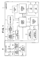
- Fig. 1 is a block diagram showing an image sensing apparatus according to an embodiment of the present invention
- Fig. 2 is a view of an image sensing element and the second curtain of a mechanical shutter when seen from the lens side along the optical axis direction;
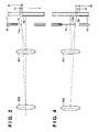
- Fig. 3 is a view showing the relationship among a mechanical second curtain, an electronic first curtain, and the pupil position of a photographing lens;
- Fig. 4 is a view showing another relationship among the mechanical second curtain, the electronic first curtain, and the pupil position of the photographing lens;
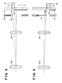
- Fig. 5 is a view showing still another relationship among the mechanical second curtain, the electronic first curtain, and the pupil position of the photographing lens;
- Fig. 6 is a view showing still another relationship among the mechanical second curtain, the electronic first curtain, and the pupil position of the photographing lens;
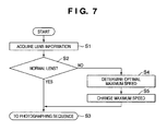
- Fig. 7 is a flowchart illustrating exposure time changing processing corresponding to the lens conditions according to the first embodiment
- Fig. 8 is a flowchart illustrating shutter switching processing corresponding to the lens conditions according to the second embodiment
- Fig. 9 is a view showing the relationship among a mechanical second curtain, an electronic first curtain, and the amount of shift of a shift lens
- Fig. 10 is a view showing another relationship among the mechanical second curtain, the electronic first curtain, and the amount of shift of the shift lens;
- Fig. 11 is a view showing still another relationship among the mechanical second curtain, the electronic first curtain, and the amount of shift of the shift lens;
- Fig. 12 is a view showing still another relationship among the mechanical second curtain, the electronic first curtain, and the amount of shift of the shift lens;
- Fig. 13 is a flowchart illustrating exposure time changing processing corresponding to the lens conditions according to the third embodiment.
- Fig. 14 is a flowchart illustrating shutter switching processing corresponding to the lens conditions according to the fourth embodiment.
- Embodiments to be described hereinafter are implementation examples of the present invention, and can be appropriately modified or changed in accordance with various conditions and the arrangement of an apparatus to which the present invention is applied. Therefore, the present invention is not particularly limited to the following embodiments.
- Fig. 1 is a block diagram showing an image sensing apparatus according to an embodiment of the present invention.
- the image sensing apparatus is, for example, a digital still camera.
- Reference numeral 1 denotes a camera body.
- An image sensing element 2 includes, for example, a CMOS sensor and receives and photoelectrically converts an optical image of an object.
- An image processing circuit 3 performs predetermined pixel interpolation processing and color conversion processing for an electric charge signal from the image sensing element 2 or data from an image memory 4. Using the sensed image data, the image processing circuit 3 performs predetermined arithmetic processing and even TTL AWB (Auto White Balance) processing based on the obtained arithmetic result.
- TTL AWB Automatic White Balance
- the data from the image processing circuit 3 is written into the image memory 4.
- a camera control circuit 5 includes an arithmetic processing circuit such as a CPU and controls the overall camera body 1.
- a timing generation circuit 6 supplies a clock signal and control signal to the image sensing element 2 and image processing circuit 3.
- a release unit 7 performs the release operation of a shutter 14.
- a switch SW1 of the release unit 7 is turned on so that the camera control circuit 5 issues an instruction to start, for example, AF (Auto Focus) processing or AE (Auto Exposure) processing.
- AF Auto Focus
- AE Automatic Exposure
- the shutter button (not shown) is operated completely (pressed fully)
- a switch SW2 of the release unit 7 is turned on so that an electric charge signal read out from the image sensing element 2 is output to the image processing circuit 3.
- An external storage unit 8 such as a hard disk stores photographed image data, and has a storage capacity large enough to store a predetermined number of still images and a moving image for a predetermined time.
- An AF unit 9 adjusts the focus position from focal length information.
- An AE unit 10 performs exposure adjustment from photometric information of an object.
- An external display unit 11 includes, for example, a liquid crystal display panel and displays, for example, the apparatus operation state or a message using, for example, a text, image, or sound in accordance with program execution by the camera control circuit 5.
- a mirror driving circuit 12 moves up or down a mirror which is obliquely inserted in the photographing optical path in a viewfinder observation state and retracted outside the photographing optical path in a photographing state.
- a shutter driving circuit 13 drives the shutter 14.
- the mechanical shutter 14 has a first curtain and second curtain and controls a light beam which enters the image sensing element 2 from a lens main body 50, and performs an image sensing operation by simultaneously using an electronic shutter and the second curtain of the shutter 14 in normal photography. That is, an electronic first curtain and mechanical second curtain are implemented by controlling reset scanning of the image sensing element 2 and travel of the second curtain of the mechanical shutter 14. In switching from the electronic first curtain to the first curtain of the mechanical shutter 14 (to be described later), the first curtain and second curtain of the mechanical shutter 14 limit the exposure time.
- the lens main body 50 is detachably, electrically connected to the camera body 1 via a connector including a communication line and power supply line.
- a photographing lens 51 includes focus lenses and zoom lenses. Although these lenses are illustrated as one lens in Fig. 1 for the sake of convenience, they are formed by complicated combinations of a large number of lenses in practice.
- An aperture 52 adjusts the light amount in photography.
- a lens control circuit 53 includes an arithmetic processing circuit such as a CPU, controls, for example, focus driving and aperture driving (to be described later), and communicates with the camera control circuit 5.
- a lens driving circuit 54 drives the photographing lens in the optical axis direction based on a command from the lens control circuit 53.
- An aperture driving circuit 55 drives the aperture 52 based on a command from the lens control circuit 53.
- the camera control circuit 5 When the switch SW1 of the release unit 7 is turned on, the camera control circuit 5 outputs an AF processing instruction to the AF unit 9, and outputs an AE processing instruction to the AE unit 10.
- the AF unit 9 determines the current defocus state.
- the camera control circuit 5 calculates focal length information from the defocus state, and outputs this information to the lens control circuit 53 of the lens main body 50. Based on the focal length information obtained by the camera control circuit 5, the lens control circuit 53 outputs a control command to the lens driving circuit 54 to drive and focus the photographing lens 51.
- the AE unit 10 measures the current brightness of an object.
- the camera control circuit 5 calculates photometric information from the photometric result, and determines the exposure time and F-number according to the camera setting.
- the camera control circuit 5 After the AF processing and AE processing are completed and the switch SW2 of the release unit 7 is turned on, the camera control circuit 5 outputs a control command to the lens control circuit 53.
- the aperture driving circuit 55 drives the aperture 52 to have a predetermined F-number, in accordance with the command from the lens control circuit 53.
- the camera control circuit 5 outputs a control command to the mirror driving circuit 12 to move a mirror (not shown) from a viewfinder observation state to a photographing state.
- the camera control circuit 5 outputs control commands to the shutter driving circuit 13 and timing generation circuit 6.
- Image sensing is performed by implementing an electronic first curtain and mechanical second curtain by controlling electric charge accumulation start scanning of the image sensing element 2 and travel of the mechanical shutter 14.
- the electric charges accumulated in the image sensing element 2 are sequentially read out to the image processing circuit 3 and undergo image processing by it.
- the processed image data is written into the image memory 4.
- the image data temporarily stored in the image memory 4 are transferred to the external storage unit 8 and recorded in it.
- Fig. 2 is a view of the image sensing element and the second curtain of the mechanical shutter when seen from the lens side along the optical axis direction.
- Fig. 2 shows reset scanning of the electronic first curtain and travel of the mechanical second curtain after photography is started by the release unit 7.
- an arrow 20 indicates both the reset scanning direction (the traveling direction of the electronic first curtain) of the electronic first curtain and the traveling direction of the mechanical second curtain.
- An object image is formed on the image sensing plane of the image sensing element 2 via the lens main body 50.
- Reference numeral 21 indicates the image sensing plane of the image sensing element 2; and 15, the mechanical second curtain of the mechanical shutter 14.
- Fig. 2 shows the state in which the mechanical second curtain 15 partially shields the image sensing plane 21 against light.
- Reference numeral 2a indicates a line (reset line) along which reset scanning of the image sensing element 2 is performed.
- the reset scanning is to reset the amounts of accumulated electric charge of pixels on the reset line 2a to zero, and the reset line 2a corresponds to the leading edge of the electronic first curtain.
- a slit region 22 between the reset line 2a and a leading edge portion 15a of the mechanical second curtain 15 is an image sensing region (electric charge accumulation region) in which the image sensing element 2 accumulates electric charges by exposure.
- the electric charge accumulation region 22 moves in the direction indicated by the arrow 20.
- the time from when the reset line 2a passes through a given pixel of the image sensing element 2, that is, from when reset scanning is started until the mechanical second curtain 15 shields the image sensing element 2 against light is the time for electric charge accumulation of the given pixel by exposure. Since the reset line 2a travels in the direction indicated by the arrow 20 and electric charge accumulation on each line starts, the electric charge accumulation start timing changes for each line of the image sensing element 2.
- Figs. 3 and 4 are views each showing the relationship among the mechanical second curtain, the electronic first curtain, and the pupil position of the photographing lens.
- reference numeral 502 denotes a lens having a long focal length and long exit pupil distance; 501, a lens having a short focal length and short exit pupil distance; 16, a shutter base plate; and 17, a shutter blade press.
- FIG. 3 shows the state in which the shutter has begun to open with a maximum speed in a photographing operation.
- a slit width A1 indicates the width of a region formed between the reset line 2a and a line 15a on which the mechanical second curtain 15 shields a light beam from the lens 501 with a short exit pupil distance.
- a slit width B1 indicates the width of a region formed between the reset line 2a and the line 15a on which the mechanical second curtain 15 shields a light beam from the lens 502 with a long exit pupil distance.
- the slit width A1 is wider than the slit width B1.
- exposure using the lens 501 takes a longer time than exposure using the lens 502 in the region with the slit width B1. Therefore, if the reset scanning pattern of the electronic first curtain is set such that the lens 501 can obtain correct exposure, underexposure occurs at the beginning of opening of the shutter upon photography by the lens 502.
- Fig. 4 shows the latter half of a photographing operation (near the end of photography).
- a slit width A2 indicates the width of a region formed between the reset line 2a and the line 15a on which the mechanical second curtain 15 shields a light beam from the lens 501 with a short focal length and short exit pupil distance.
- a slit width B2 indicates the width of a region formed between the reset line 2a and the line 15a on which the mechanical second curtain 15 shields a light beam from the lens 502 with a long focal length and long exit pupil distance.
- the slit width B2 is wider than the slit width A2 in contrast to the beginning of opening of the shutter shown in Fig. 3 .
- exposure using the lens 501 takes a longer time than exposure using the lens 502 in the region with the slit width A2. Therefore, if the reset scanning pattern of the electronic first curtain is set such that the lens 501 can obtain correct exposure, overexposure occurs upon photography by the lens 502.
- an optimal reset scanning timing of the electronic first curtain changes depending on the difference in pupil position.
- a slit width A1' corresponding to a lens 501 with a short exit pupil distance is about twice the slit width A1 shown in Fig. 3 .
- a slit width B1' corresponding to a lens 502 with a long exit pupil distance is shorter than the slit width A1', but the difference between the slit widths A1' and B1' is very small as compared with that between the slit widths A1 and B1 shown in Fig. 3 .
- a slit width A2' corresponding to a lens 501 with a short exit pupil distance is about twice the slit width A2 shown in Fig. 4 .
- a slit width B2' corresponding to a lens 502 with a long exit pupil distance is shorter than the slit width A2', but the difference between the slit widths A2' and B2' is very small as compared with that between the slit widths A2 and B2 shown in Fig. 4 .
- the amount of error with respect to the shutter speed decreases in proportion. That is, the amount of error decreases to 1/2 if the maximum shutter speed is halved, and it decreases to 1/4 if the maximum shutter speed is halved again.
- Figs. 3 and 4 show the state in which the shutter speed is a maximum. Slowing down the shutter speed from the maximum one by two steps makes it possible to eliminate errors of the pupil positions of nearly all the lenses. This is because when the shutter speed slows down to below about 1/2000 seconds, the difference in slit width attributed to the pupil position of each lens becomes negligibly small.
- a camera control circuit 5 acquires information associated with a lens from a lens main body 50 (S1).
- the camera control circuit 5 communicates with a lens control circuit 53 of the lens main body 50 to transmit/receive necessary information on the lens main body 50 mounted on a camera body 1 to/from the lens control circuit 53.
- the camera control circuit 5 determines the lens conditions from the lens information acquired in step S1 (S2). If the camera control circuit 5 determines in step S2 that the lens main body 50 is a normal lens, the processing shifts to a photographing sequence (S3). Then, the camera control circuit 5 sets an optimal traveling characteristic of an electronic first curtain in accordance with the lens information acquired in step S1.
- step S2 If the camera control circuit 5 determines in step S2 that information associated with the lens pupil position is absent or is not found, an optimal traveling characteristic of the electronic first curtain cannot be obtained and an optimal maximum shutter speed is set for all the lenses (S4). More specifically, the maximum shutter speed is slowed down by about two steps. That is, if the maximum shutter speed is 1/8000 seconds, it is slowed down to about 1/2000 seconds. This makes it possible to obtain an appropriate image with low unevenness of exposure, as described with reference to Figs. 5 and 6 .
- the camera control circuit 5 changes the setting value of the maximum speed to the one determined in step S4, and the processing shifts to the photographing sequence (S3).
- the determination in step S2 may be done in accordance with the presence/absence of a device to change the lens pupil position or the presence/absence of an extension tube, in addition to the presence/absence of information associated with the lens pupil position.
- a predetermined shutter speed is set as the maximum shutter speed.
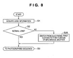
- Shutter switching processing corresponding to the lens conditions according to the second embodiment will be explained next with reference to the sequence illustrated in Fig. 8 .
- the second embodiment is different from the first embodiment in that if a camera control circuit 5 determines in step S2 that a lens main body 50 is not a normal lens, switching is performed from an electronic first curtain to the first curtain of a mechanical shutter in step S25. This makes it possible to obtain an image with correct exposure because the mechanical shutter has no error compared with the electronic first curtain.
- Figs. 9 and 10 are views each showing the relationship between the mechanical second curtain, the electronic first curtain, and the amount of shift of the shift lens.
- the same reference numerals as in Figs. 3 and 4 denote corresponding members in Figs. 9 and 10 .
- reference numeral 601 indicates the state in which a shift lens has not shifted; and 601', the state in which a shift lens has largely shifted.
- Fig. 9 shows the state in which the shutter has begun to open with a maximum speed in a photographing operation.
- a slit width C1 indicates the width of a region formed between a reset line 2a and a line 15a on which a mechanical second curtain 15 shields a light beam from the lens 601 with zero amount of shift.
- a slit width D1 indicates the width of a region formed between the reset line 2a and the line 15a on which the mechanical second curtain 15 shields a light beam from the lens 601' with a large amount of shift.
- the slit width C1 is wider than the slit width D1.
- exposure using the lens 601 with zero amount of shift takes a longer time than exposure using the lens 601' with a large amount of shift in the region with the slit width D1. Therefore, if the reset scanning pattern of the electronic first curtain is set such that the lens 601 with zero amount of shift can obtain correct exposure, underexposure occurs at the beginning of opening of the shutter upon photography by the lens 601'.
- Fig. 10 shows the latter half of a photographing operation (near the end of photography).
- a slit width C2 indicates the width of a region formed between the reset line 2a and the line 15a on which the mechanical second curtain 15 shields a light beam from the lens 601 with zero amount of shift.
- a slit width D2 indicates the width of a region formed between the reset line 2a and the line 15a on which the mechanical second curtain 15 shields a light beam from the lens 601' with a large amount of shift.
- the slit width D2 is shorter than the slit width C2 as in the beginning of opening of the shutter shown in Fig. 9 .
- exposure using the lens 601 with zero amount of shift takes a longer time than exposure using the lens 601' in the region with the slit width D2. Therefore, if the reset scanning pattern of the electronic first curtain is set such that the lens 501 can obtain correct exposure, underexposure occurs at the end of opening of the shutter upon photography by the lens 601' with a large amount of shift.
- a slit width C1' corresponding to a lens 601 with zero amount of shift is about twice the slit width C1 shown in Fig. 9 .
- a slit width D1' corresponding to a lens 601' with a large amount of shift is shorter than the slit width C1' with zero amount of shift, but the difference between the slit widths C1' and D1' is very small as compared with that between the slit widths C1 and D1 shown in Fig. 9 .
- a slit width C2' corresponding to a lens 601 with zero amount of shift is about twice the slit width C2 shown in Fig. 10 .
- a slit width D2' corresponding to a lens 601' with a large amount of shift is shorter than the slit width C2' with zero amount of shift, but the difference between the slit widths C2' and D2' is very small as compared with that between the slit widths C2 and D2 shown in Fig. 10 .
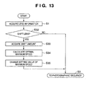
- a camera control circuit 5 determines in step S32 that a lens main body 50 is a shift lens, it acquires the amount of shift from the lens main body 50 (S33).
- the camera control circuit 5 calculates an optimal maximum shutter speed from the amount of shift acquired in step S33 (S34). In this case, the maximum shutter speed is slowed down in accordance with the magnitude of the amount of shift.
- the camera control circuit 5 changes the setting value of the maximum speed to the one calculated in step S34, and the processing shifts to the photographing sequence (S3) (S35).
- the third embodiment when a shift lens is mounted on the apparatus, it is possible to determine and set an optimal maximum shutter speed from the amount of shift. This makes it possible to obtain an image with correct exposure even when a shift lens is used for an electronic first curtain.
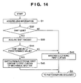
- Shutter switching processing corresponding to the lens conditions according to the fourth embodiment will be explained with reference to the sequence illustrated in Fig. 14 .
- the fourth embodiment is different from the third embodiment in the following points. That is, if a camera control circuit 5 determines in steps S32 and S44 that a lens main body 50 is a shift lens (S32) and has an amount of shift equal to or larger than a predetermined value (S44), switching is performed from an electronic first curtain to the first curtain of a mechanical shutter in step S45. If the camera control circuit 5 determines in step S44 that the amount of shift is smaller than the predetermined value, the electronic first curtain is maintained in step S46. The mechanical shutter has no error as in the electronic first curtain. Hence, even when a shift lens is mounted on the apparatus, it is possible to obtain an image with correct exposure by switching to the first curtain of the mechanical shutter if the amount of shift is equal to or larger than the predetermined value.
- switching may be performed to the first curtain of the mechanical shutter as in the case in which a shift lens is mounted on the apparatus.
- a storage medium (or recording medium) which stores software program codes for implementing the functions of the above-described embodiments is supplied to a camera.
- the computer or CPU or MPU
- the computer or CPU or MPU
Landscapes
- Engineering & Computer Science (AREA)
- Multimedia (AREA)
- Signal Processing (AREA)
- Physics & Mathematics (AREA)
- General Physics & Mathematics (AREA)
- Studio Devices (AREA)
- Shutters For Cameras (AREA)
- Transforming Light Signals Into Electric Signals (AREA)
- Exposure Control For Cameras (AREA)
Claims (8)
- Bildaufnahmevorrichtung, umfassend:eine Bildaufnahmeeinrichtung (2) mit einem oder mehr Bildaufnahmebereichen (22), ausgebildet zum Empfangen eines Objektbildes über ein an der Bildaufnahmevorrichtung angebrachtes Objektiv und zum Speichern des empfangenen Bildes in Form von elektrischer Ladung;einen mechanischen Verschluss (14), ausgebildet zum Bewegen, um die einen oder mehr Bildaufnahmebereiche (22) gegen Licht abzuschirmen;eine Scaneinrichtung (5, 6), ausgebildet zum Ausführen von Scannen zum sequentiellen Starten des Speicherns der elektrischen Ladung für jeden der ein oder mehr Bildaufnahmebereiche der Bildaufnahmeeinrichtung;eine Steuereinrichtung (5), ausgebildet zum Steuern des Scannens der Scaneinrichtung und des mechanischen Verschlusses, um so einen elektronischen ersten Vorhang und einen mechanischen zweiten Vorhang (15) zu liefern; undeine Änderungseinrichtung (5), ausgebildet zum automatischen Ändern einer einstellbaren Mindest-Belichtungszeit, basierend auf Information über das Objektiv.
- Vorrichtung nach Anspruch 1, wobei die Änderungseinrichtung ausgelegt ist zum Verlängern der einstellbaren Mindest-Belichtungszeit, wenn einer oder mehr der folgenden Umstände auftreten: Der Objektivtyp ist ein Shift-Objektiv (601, 601'), Information über die Pupillenposition des Objektivs wird nicht gefunden, ein Shift-Betrag des Shift-Objektivs wird nicht gefunden, ein Device zum Ändern der Pupillenposition des Objektivs fehlt oder ein Zwischenring fehlt.
- Vorrichtung nach einem der vorhergehenden Ansprüche, bei welcher die Information über das Objektiv der Objektivtyp ist.
- Vorrichtung nach einem der vorhergehenden Ansprüche, die ein an ihr angebrachtes Objektiv einschließt.
- Steuerverfahren für eine Bildaufnahmevorrichtung, die umfasst:eine Bildaufnahmeeinheit, ausgebildet zum Empfangen eines Objektbildes über ein Objektiv und zum Speichern des empfangenen Bildes in Form von elektrischer Ladung;eine mechanische Verschlusseinheit, ausgebildet zum Bewegen, um einen Bildaufnahmebereich der Bildaufnahmeeinheit gegen Licht abzuschirmen;eine Scaneinheit, ausgebildet zum Ausführen von Scannen zum sequentiellen Starten des Speicherns der elektrischen Ladung für jeden Bildaufnahmebereich der Bildaufnahmeeinheit; undeine Steuereinheit, ausgebildet zum Steuern des Speicherstartscannens der Scaneinheit und der Bewegung eines Verschlusses der mechanischen Verschlusseinheit, um einen ersten Vorhang und einen zweiten Vorhang (5) eines Verschlusses zu implementieren, wobei das Verfahren umfasst:automatisches Ändern einer einstellbaren Mindest-Belichtungszeit, basierend auf mindestens dem Objektivtyp und/oder Information über das Objektiv.
- Verfahren nach Anspruch 5, wobei im Änderungsschritt die einstellbare Mindest-Belichtungszeit verlängert wird (S34, S35), wenn einer oder mehr der folgenden Umstände auftreten: Der Objektivtyp ist ein Shift-Objektiv (S32), Information über eine Pupillenposition des Objektivs wird nicht gefunden, ein Shift-Betrag des Shift-Objektivs wird nicht gefunden, ein Device zum Ändern der Pupillenposition des Objektivs fehlt oder ein Zwischenring fehlt.
- Computerprogramm, das, wenn es auf einen Computer einer Kamera geladen wird, ein Verfahren nach einem der Ansprüche 5 oder 6 ausführt.
- Maschinenlesbares Speichermedium, das ein Computerprogramm nach Anspruch 7 speichert.
Applications Claiming Priority (1)
| Application Number | Priority Date | Filing Date | Title |
|---|---|---|---|
| JP2007149644A JP5335202B2 (ja) | 2007-06-05 | 2007-06-05 | 撮像装置及びその制御方法 |
Publications (2)
| Publication Number | Publication Date |
|---|---|
| EP2015563A1 EP2015563A1 (de) | 2009-01-14 |
| EP2015563B1 true EP2015563B1 (de) | 2010-11-17 |
Family
ID=39744728
Family Applications (1)
| Application Number | Title | Priority Date | Filing Date |
|---|---|---|---|
| EP08157682A Not-in-force EP2015563B1 (de) | 2007-06-05 | 2008-06-05 | Bildaufnahmevorrichtung und Steuerverfahren dafür |
Country Status (5)
| Country | Link |
|---|---|
| US (1) | US7918616B2 (de) |
| EP (1) | EP2015563B1 (de) |
| JP (1) | JP5335202B2 (de) |
| CN (1) | CN101321229A (de) |
| DE (1) | DE602008003486D1 (de) |
Families Citing this family (7)
| Publication number | Priority date | Publication date | Assignee | Title |
|---|---|---|---|---|
| KR101170459B1 (ko) | 2009-11-03 | 2012-08-07 | 삼성전자주식회사 | 촬영 장치 제어 방법 및 이를 이용한 촬영 장치 |
| KR20110076729A (ko) * | 2009-12-18 | 2011-07-06 | 삼성전자주식회사 | 전자 셔터를 이용한 다단계 노출 이미지 획득 방법 및 이를 이용한 촬영 장치 |
| JP2011191616A (ja) * | 2010-03-16 | 2011-09-29 | Panasonic Corp | 撮像装置 |
| JP5402857B2 (ja) * | 2010-07-05 | 2014-01-29 | 株式会社ニコン | 撮像装置及びレンズ鏡筒 |
| JP5621569B2 (ja) | 2010-12-13 | 2014-11-12 | ソニー株式会社 | 撮像装置及びシャッタ動作補正方法 |
| CN102685392A (zh) * | 2011-03-07 | 2012-09-19 | 精工爱普生株式会社 | 数码相机及其快门动作推断方法 |
| CN113014913B (zh) * | 2019-12-19 | 2022-09-06 | 合肥君正科技有限公司 | 一种车内监控相机分段模式遮挡检测的方法 |
Citations (2)
| Publication number | Priority date | Publication date | Assignee | Title |
|---|---|---|---|---|
| GB2229282A (en) * | 1989-02-10 | 1990-09-19 | Asahi Optical Co Ltd | Exposure control system of an interval mode camera |
| US5280319A (en) * | 1991-04-15 | 1994-01-18 | Asahi Kogaku Kogyo Kabushiki Kaisha | Exposure control apparatus of camera including exposure factor limit value setting means |
Family Cites Families (5)
| Publication number | Priority date | Publication date | Assignee | Title |
|---|---|---|---|---|
| JP3988215B2 (ja) | 1997-07-17 | 2007-10-10 | 株式会社ニコン | 撮像装置 |
| WO2006036921A1 (en) | 2004-09-28 | 2006-04-06 | Eastman Kodak Company | Image capturing device |
| JP4974596B2 (ja) * | 2005-07-22 | 2012-07-11 | キヤノン株式会社 | 撮像装置及びその制御方法 |
| JP2007033543A (ja) * | 2005-07-22 | 2007-02-08 | Fujifilm Holdings Corp | 撮影装置 |
| JP4724539B2 (ja) * | 2005-11-24 | 2011-07-13 | キヤノン株式会社 | 実露光時間算出方法ならびにそれを適用した撮像装置、光学機器、カメラシステムおよび実露光時間測定器 |
-
2007
- 2007-06-05 JP JP2007149644A patent/JP5335202B2/ja not_active Expired - Fee Related
-
2008
- 2008-05-21 US US12/124,787 patent/US7918616B2/en not_active Expired - Fee Related
- 2008-06-05 EP EP08157682A patent/EP2015563B1/de not_active Not-in-force
- 2008-06-05 CN CNA2008101112028A patent/CN101321229A/zh active Pending
- 2008-06-05 DE DE602008003486T patent/DE602008003486D1/de active Active
Patent Citations (2)
| Publication number | Priority date | Publication date | Assignee | Title |
|---|---|---|---|---|
| GB2229282A (en) * | 1989-02-10 | 1990-09-19 | Asahi Optical Co Ltd | Exposure control system of an interval mode camera |
| US5280319A (en) * | 1991-04-15 | 1994-01-18 | Asahi Kogaku Kogyo Kabushiki Kaisha | Exposure control apparatus of camera including exposure factor limit value setting means |
Also Published As
| Publication number | Publication date |
|---|---|
| US20080304820A1 (en) | 2008-12-11 |
| DE602008003486D1 (de) | 2010-12-30 |
| CN101321229A (zh) | 2008-12-10 |
| JP2008304565A (ja) | 2008-12-18 |
| JP5335202B2 (ja) | 2013-11-06 |
| EP2015563A1 (de) | 2009-01-14 |
| US7918616B2 (en) | 2011-04-05 |
Similar Documents
| Publication | Publication Date | Title |
|---|---|---|
| JP5003543B2 (ja) | 撮像装置、および信号処理方法、並びにコンピュータ・プログラム | |
| JP5693355B2 (ja) | 撮像装置及びその制御方法、プログラム、記憶媒体 | |
| EP2015563B1 (de) | Bildaufnahmevorrichtung und Steuerverfahren dafür | |
| JP2006345172A (ja) | ファインダ装置及びカメラ | |
| JP2001174690A (ja) | 自動焦点調節装置、自動露出装置、自動調光装置、光学装置及びカメラ | |
| JP3800230B2 (ja) | 撮像装置、およびフラッシュ同調速度の設定方法 | |
| CN101373254A (zh) | 摄影装置及摄影装置的控制方法 | |
| JP3632677B2 (ja) | 電子カメラ | |
| JP5532565B2 (ja) | カメラ | |
| JP5333888B2 (ja) | 撮像装置及びそのプログラム | |
| JP7458715B2 (ja) | 撮影装置、その制御方法、プログラム、並びに記録媒体 | |
| JP4963713B2 (ja) | 電子カメラ及びその制御方法及びプログラム及び記憶媒体 | |
| JP7229709B2 (ja) | 撮像装置およびその制御方法 | |
| JP2009122557A (ja) | カメラ | |
| JP2007060131A (ja) | ライブビュー表示機能を有するカメラ | |
| JP5247876B2 (ja) | 電子カメラ及びその制御方法 | |
| JP2009089330A (ja) | 撮像装置 | |
| JP5039496B2 (ja) | 撮像装置及びその制御方法 | |
| JP4827526B2 (ja) | 光学機器 | |
| JP2007065334A (ja) | レンズ交換式カメラシステム | |
| JP2005175961A (ja) | 撮像装置、撮像感度制御方法、シャッタ制御方法、及びプログラム | |
| JP2006174023A (ja) | 撮影装置 | |
| JP2006201568A (ja) | 手ぶれ検出可能なカメラ | |
| JP5587078B2 (ja) | 撮像装置及びその制御方法 | |
| JP2005136654A (ja) | カメラ |
Legal Events
| Date | Code | Title | Description |
|---|---|---|---|
| PUAI | Public reference made under article 153(3) epc to a published international application that has entered the european phase |
Free format text: ORIGINAL CODE: 0009012 |
|
| PUAI | Public reference made under article 153(3) epc to a published international application that has entered the european phase |
Free format text: ORIGINAL CODE: 0009012 |
|
| AK | Designated contracting states |
Kind code of ref document: A1 Designated state(s): AT BE BG CH CY CZ DE DK EE ES FI FR GB GR HR HU IE IS IT LI LT LU LV MC MT NL NO PL PT RO SE SI SK TR |
|
| AX | Request for extension of the european patent |
Extension state: AL BA MK RS |
|
| 17P | Request for examination filed |
Effective date: 20090714 |
|
| AKX | Designation fees paid |
Designated state(s): DE FR GB IT |
|
| 17Q | First examination report despatched |
Effective date: 20091120 |
|
| GRAP | Despatch of communication of intention to grant a patent |
Free format text: ORIGINAL CODE: EPIDOSNIGR1 |
|
| GRAS | Grant fee paid |
Free format text: ORIGINAL CODE: EPIDOSNIGR3 |
|
| GRAA | (expected) grant |
Free format text: ORIGINAL CODE: 0009210 |
|
| AK | Designated contracting states |
Kind code of ref document: B1 Designated state(s): DE FR GB IT |
|
| REG | Reference to a national code |
Ref country code: GB Ref legal event code: FG4D |
|
| REF | Corresponds to: |
Ref document number: 602008003486 Country of ref document: DE Date of ref document: 20101230 Kind code of ref document: P |
|
| PLBE | No opposition filed within time limit |
Free format text: ORIGINAL CODE: 0009261 |
|
| STAA | Information on the status of an ep patent application or granted ep patent |
Free format text: STATUS: NO OPPOSITION FILED WITHIN TIME LIMIT |
|
| 26N | No opposition filed |
Effective date: 20110818 |
|
| REG | Reference to a national code |
Ref country code: DE Ref legal event code: R097 Ref document number: 602008003486 Country of ref document: DE Effective date: 20110818 |
|
| REG | Reference to a national code |
Ref country code: FR Ref legal event code: PLFP Year of fee payment: 9 |
|
| PGFP | Annual fee paid to national office [announced via postgrant information from national office to epo] |
Ref country code: GB Payment date: 20160627 Year of fee payment: 9 |
|
| PGFP | Annual fee paid to national office [announced via postgrant information from national office to epo] |
Ref country code: IT Payment date: 20160608 Year of fee payment: 9 Ref country code: FR Payment date: 20160627 Year of fee payment: 9 |
|
| PGFP | Annual fee paid to national office [announced via postgrant information from national office to epo] |
Ref country code: DE Payment date: 20160630 Year of fee payment: 9 |
|
| REG | Reference to a national code |
Ref country code: DE Ref legal event code: R119 Ref document number: 602008003486 Country of ref document: DE |
|
| GBPC | Gb: european patent ceased through non-payment of renewal fee |
Effective date: 20170605 |
|
| REG | Reference to a national code |
Ref country code: FR Ref legal event code: ST Effective date: 20180228 |
|
| PG25 | Lapsed in a contracting state [announced via postgrant information from national office to epo] |
Ref country code: GB Free format text: LAPSE BECAUSE OF NON-PAYMENT OF DUE FEES Effective date: 20170605 Ref country code: DE Free format text: LAPSE BECAUSE OF NON-PAYMENT OF DUE FEES Effective date: 20180103 |
|
| PG25 | Lapsed in a contracting state [announced via postgrant information from national office to epo] |
Ref country code: FR Free format text: LAPSE BECAUSE OF NON-PAYMENT OF DUE FEES Effective date: 20170630 Ref country code: IT Free format text: LAPSE BECAUSE OF NON-PAYMENT OF DUE FEES Effective date: 20170605 |