EP2015299A2 - Optische Bank, integriertes optisches System und optisches Ausrichtungsverfahren - Google Patents
Optische Bank, integriertes optisches System und optisches Ausrichtungsverfahren Download PDFInfo
- Publication number
- EP2015299A2 EP2015299A2 EP08168056A EP08168056A EP2015299A2 EP 2015299 A2 EP2015299 A2 EP 2015299A2 EP 08168056 A EP08168056 A EP 08168056A EP 08168056 A EP08168056 A EP 08168056A EP 2015299 A2 EP2015299 A2 EP 2015299A2
- Authority
- EP
- European Patent Office
- Prior art keywords
- optical
- lens unit
- lens
- light
- bench
- Prior art date
- Legal status (The legal status is an assumption and is not a legal conclusion. Google has not performed a legal analysis and makes no representation as to the accuracy of the status listed.)
- Withdrawn
Links
- 230000003287 optical effect Effects 0.000 title claims abstract description 254
- 238000000034 method Methods 0.000 title claims abstract description 22
- 238000013519 translation Methods 0.000 claims description 9
- 238000012360 testing method Methods 0.000 description 10
- 238000004519 manufacturing process Methods 0.000 description 4
- 239000004065 semiconductor Substances 0.000 description 2
- XUIMIQQOPSSXEZ-UHFFFAOYSA-N Silicon Chemical compound [Si] XUIMIQQOPSSXEZ-UHFFFAOYSA-N 0.000 description 1
- 230000004075 alteration Effects 0.000 description 1
- 238000006243 chemical reaction Methods 0.000 description 1
- 238000010276 construction Methods 0.000 description 1
- 230000003247 decreasing effect Effects 0.000 description 1
- 238000011161 development Methods 0.000 description 1
- 238000005516 engineering process Methods 0.000 description 1
- 238000009434 installation Methods 0.000 description 1
- 239000000463 material Substances 0.000 description 1
- 238000012544 monitoring process Methods 0.000 description 1
- 229910052710 silicon Inorganic materials 0.000 description 1
- 239000010703 silicon Substances 0.000 description 1
- 239000000758 substrate Substances 0.000 description 1
Images



Classifications
-
- G—PHYSICS
- G11—INFORMATION STORAGE
- G11B—INFORMATION STORAGE BASED ON RELATIVE MOVEMENT BETWEEN RECORD CARRIER AND TRANSDUCER
- G11B7/00—Recording or reproducing by optical means, e.g. recording using a thermal beam of optical radiation by modifying optical properties or the physical structure, reproducing using an optical beam at lower power by sensing optical properties; Record carriers therefor
- G11B7/08—Disposition or mounting of heads or light sources relatively to record carriers
-
- G—PHYSICS
- G02—OPTICS
- G02B—OPTICAL ELEMENTS, SYSTEMS OR APPARATUS
- G02B27/00—Optical systems or apparatus not provided for by any of the groups G02B1/00 - G02B26/00, G02B30/00
- G02B27/62—Optical apparatus specially adapted for adjusting optical elements during the assembly of optical systems
-
- G—PHYSICS
- G02—OPTICS
- G02B—OPTICAL ELEMENTS, SYSTEMS OR APPARATUS
- G02B7/00—Mountings, adjusting means, or light-tight connections, for optical elements
- G02B7/003—Alignment of optical elements
-
- G—PHYSICS
- G11—INFORMATION STORAGE
- G11B—INFORMATION STORAGE BASED ON RELATIVE MOVEMENT BETWEEN RECORD CARRIER AND TRANSDUCER
- G11B7/00—Recording or reproducing by optical means, e.g. recording using a thermal beam of optical radiation by modifying optical properties or the physical structure, reproducing using an optical beam at lower power by sensing optical properties; Record carriers therefor
- G11B7/08—Disposition or mounting of heads or light sources relatively to record carriers
- G11B7/082—Aligning the head or the light source relative to the record carrier otherwise than during transducing, e.g. adjusting tilt set screw during assembly of head
-
- G—PHYSICS
- G11—INFORMATION STORAGE
- G11B—INFORMATION STORAGE BASED ON RELATIVE MOVEMENT BETWEEN RECORD CARRIER AND TRANSDUCER
- G11B7/00—Recording or reproducing by optical means, e.g. recording using a thermal beam of optical radiation by modifying optical properties or the physical structure, reproducing using an optical beam at lower power by sensing optical properties; Record carriers therefor
- G11B7/12—Heads, e.g. forming of the optical beam spot or modulation of the optical beam
- G11B7/135—Means for guiding the beam from the source to the record carrier or from the record carrier to the detector
- G11B7/1395—Beam splitters or combiners
-
- G—PHYSICS
- G11—INFORMATION STORAGE
- G11B—INFORMATION STORAGE BASED ON RELATIVE MOVEMENT BETWEEN RECORD CARRIER AND TRANSDUCER
- G11B7/00—Recording or reproducing by optical means, e.g. recording using a thermal beam of optical radiation by modifying optical properties or the physical structure, reproducing using an optical beam at lower power by sensing optical properties; Record carriers therefor
- G11B7/12—Heads, e.g. forming of the optical beam spot or modulation of the optical beam
- G11B7/22—Apparatus or processes for the manufacture of optical heads, e.g. assembly
Definitions
- the present invention relates to an optical bench, an integrated optical system, and an optical alignment method. More particularly, the present invention relates to an optical bench, an integrated optical system and an optical alignment method for easy assembly of optical elements and easy and simple optical alignment.
- information storage capacity is determined according to the size of the light spot.
- the size S of a light spot is defined as Equation 1 based on a wavelength, ⁇ , of a laser beam and a numerical aperture NA of an objective lens: S ⁇ ⁇ / NA
- an information recording/reproducing system using a short-wavelength light source such as a blue laser and an objective lens having a NA of at least 0.6 has been researched and developed.
- an objective lens has a NA of 0.65 or 0.85 for the high-density information storage media.
- the thickness of a CD is 1.2 mm
- the thickness of a DVD is reduced to 0.6 mm to secure tolerance in accordance with a tilt of an information storage medium. This is because an NA for the DVD isincreased to 0.6 compared to an NA of 0.45 for the CD.
- the thickness of the high-density information storage medium needs to be reduced to about 0.1 mm.
- Such information storage media developed by increasing the NA of an objective lens and decreasing the thickness of an information storage medium are Blu-ray discs (BDs).
- BDs Blu-ray discs
- the wavelength of a light source is 405 nm
- the NA of an objective lens is 0.85
- the thickness of an information storage medium is about 0.1 mm.
- AODs advanced optical discs
- the same substrate thickness and the same NA of an objective lens as those for a DVD and the same wavelength of a light source as that for a BD, i.e., a blue wavelength, e.g., a 405 nm wavelength are adopted for an AOD.
- an entire optical system forming an optical pickup is required to be thinner and smaller.
- an information recording/reproducing system for portable terminals such as personal digital assistants (PDAs), mobile phones, digital cameras, portable disc players, and camcorders
- the need for a thin optical pickup has also increased.
- the optical pickup must be able to record and/or reproduce information at high density to store and reproduce a large amount of information like music and video.
- optical pickups are manufactured through procedures of assembling and aligning a plurality of optical elements manufactured separately. During the assembly and alignment procedures, the optical elements are liable to be broken due to micro-miniaturization. Moreover, reliability and an automation rate are low due to assembly tolerance between the optical elements.
- micro optical pickups In order to manufacture micro optical pickups, it is needed to simplify the structure of a photodetector used for an optical pickup. However, if the structure of a photodetector is simplified, work of aligning optical elements becomes complicated. In other words, there is close correlation between optical alignment and realizing miniaturization of an optical pickup by simplifying the structure of a photodetector.
- optical elements are aligned using three-axis translation and two-axis tilt.
- an optical bench is frequently broken, causing optical alignment to be difficult.
- an optical bench on which a light source, a main photodetector receiving light reflected from a disc, a lens unit, and an optical path separator separating light coming from the light source and light coming from the lens unit are installed, the optical bench including a landing recess which is open upward to receive the optical path separator therein and which has an aperture on a bottom thereof to pass light.
- the optical bench may further include on a bottom surface thereof: a first mirror changing a direction of the light emitted from the light source toward the lens unit; and a second mirror changing a direction of light that has come from lens unit and then reflected from the first mirror toward the main photodetector.
- an integrated optical system including: a light source; a main photodetector receiving light that is emitted from the light source and then reflected from a disc; an optical bench on which the light source and the main photodetector are installed; a lens unit installed on the optical bench; and an optical path separator separating a path of light advancing from the light source to the lens unit and a path of light advancing from the lens unit, wherein the optical bench comprises a landing recess which is open upward to receive the optical path separator therein and which has an aperture on a bottom thereof to pass light.
- the lens unit may be an objective lens or a collimating lens.
- the integrated optical system may further include an objective lens above the collimating lens so that the integrated optical system is used as a holographic module.
- the lens unit may be a hybrid lens comprising a refractive lens and diffractive lens.
- the integrated optical system may further include on a bottom surface of the optical bench a monitor photodetector detecting power of the light emitted from the light source.
- the optical path separator may be one of a holographic optical element and a diffractive optical element.
- an optical alignment method for an integrated optical system including: supporting an optical bench mounted with a lens unit with a first jig and adjusting a tilt of the optical bench using the first jig, thereby aligning the optical bench to an optical axis; and supporting a dummy optical path separator with a second jig and adjusting a tilt of the dummy optical path separator using the second jig, thereby preliminary aligning the dummy optical path separator to the optical axis, wherein the first jig and the second jig are set for tilt aligning of the integrated optical system.
- the optical alignment method may further include supporting a dummy disc with a third jig and adjusting a tilt of the dummy disc, thereby preliminary aligning the dummy disc to the optical axis.
- the optical alignment method may further include: replacing the dummy optical path separator with an optical path separator to be assembled; and translating the optical path separator.
- the present invention provides an optical bench and an integrated optical system, which have improved structures for simplifying assembly work.
- the present invention also provides an optical alignment method for simplifying optical alignment in an assembled state by preliminarily completing tilt alignment about an optical axis.
- FIG. 1A is a perspective view of an integrated optical system including an optical bench according to an embodiment of the present invention.
- FIG. 1B is a front view of the integrated optical system shown in FIG. 1A .
- the integrated optical system includes a light source 10, an optical bench 20 mounted with a main photodetector 15, and an optical path separator 25 installed in a landing recess 24 formed in the optical bench to open upward.
- the light source 10 may be implemented to emit light in diverse wavelength bands according to a type of information storage medium used in the integrated optical system.
- the light source 10 may be implemented to emit red-wavelength light or blue-wavelength light or to emit light in plural wavelengths so that the light source 10 is compatible with diverse types of information storage media.
- information storage media adapting to an integrated optical system according to the present invention may be compact discs (CDs), digital versatile discs (DVDs), Blu-ray discs (BDs), and advanced optical discs (AODs).
- the optical bench 20 may be a silicon opticalbench (SiOB).
- the light source 10, the main photodetector 15 receiving light emitted from the light source 10 and then reflected from an information storage medium, and a monitor photodetector 23 monitoring the power of light emitted from the light source 10 are mounted on a bottom surface 20a of the optical bench 20.
- the light source 10 may be implemented by an edge-emitting semiconductor laser emitting a laser beam to a side of a semiconductor material layer. In this case, the light source 10 is placed on a mount 12 and the monitor photodetector 23 is disposed in front of the light source 10 so that the monitor photodetector 23 receives part of the light emitted from the light source 10.
- the main photodetector 15 receives light reflected from an information storage medium and detects an information playback signal and a focusing error signal, tracking error signal and tilt error signal for servo driving.
- the optical path separator 25 is disposed in the landing recess 24 formed on one side of the optical bench 20 to open upward.
- An aperture 22 is formed on the bottom of the landing recess 23 to allow light pass therethrough.
- a lens unit 27 is mounted upward the landing recess 23.
- the optical path separator 25 separates a path of light advancing from the light source 10 to the lens unit 27 and a path of light advancing from the lens unit 27.
- the optical path separator 25 may be implemented by a diffractive optical element or a holographic optical element.
- the lens unit 27 may be an objective lens focusing light on an information storage medium.
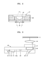
- the lens unit 27 may be a hybrid lens including a refractive lens 28 and a diffractive lens 29, as shown in FIG. 2 .
- the refractive lens 28 is inserted into a lens holder 30 and the diffractive lens 29 is formed on one side of the lens holder 30.
- the refractive lens 28 having one convex side is easy to manufacture and the diffractive lens 29 compensates for chromatic aberration.
- a first mirror 31 is disposed at one side on the bottom surface 20a of the optical bench 20 to reflect light from the light source 10 to the optical path separator 25.
- a second mirror 32 is disposed at an opposite side on the bottom surface 20a to reflect light coming from the lens unit 27 via the optical path separator 25 and the first mirror 31 to the main photodetector 15.
- the optical bench 20 according to an embodiment of the present invention is characterized by a structure in which the landing recess 24 for installation of the optical path separator 25 is open upward.
- This structure is advantageous in that the optical path separator 25 is assembled to the optical bench 20 just by putting the optical path separator 25 in the landing recess 24. Since an integrated optical system of the present invention has a micro size, an optical bench is liable to damage during assembly of optical elements to the optical bench, and therefore, the assembly may be very difficult.
- the optical bench 20 according to an embodiment of the present invention facilitates the assembly.
- the lens unit 27 is assembled after the optical path separator 25 is provisionally bonded.
- the provisional bonding of the optical path separator 25 is not required, thereby simplifying the assembly.
- An integrated optical system according to an embodiment of the present invention may be used as an optical pickup or a holographic module according to the structure of the lens unit 27.
- the present invention provides a structure facilitating conversion between an optical pickup and a holographic optical module during manufacturing of an integrated optical system. Accordingly, an integrated optical system according to the present invention can be converted into an optical pickup or a holographic optical module as occasion demands.
- the lens unit 27 is implemented by an objective lens.
- FIG. 1B illustrates an example in which the integrated optical system is used as an optical pickup.
- FIG. 3 illustrates an example in which the integrated optical system shown in FIG. 1A is used as a holographic optical module.
- the lens unit 27 is implemented by a collimating lens and an objective lens 35 is disposed above the collimating lens.
- Light emitted from the light source 10 is output through the holographic module and is incident onto the objective lens 35 in parallel via the collimating lens.
- the light having passed through the objective lens 35 is focused on an information storage medium D and records data onto or reproduces data from the information storage medium D.
- only he objective lens 35 is driven by an actuator for focusing, tracking, and/or tilting.
- the light reflected from the information storage medium D passes through the objective lens 35 and the lens unit 27 implemented by the collimating lens and is incident onto the optical path separator 25, which converts the path of the light. Then, the light is reflected by the first mirror 31 and reaches the second mirror 32 after avoiding the interference by the light source 10 and the mount 12. Thereafter, the light is reflected by the second mirror 32 and received by the main photodetector 15. As a result, information recorded in the information storage medium D is read and a focus, tracking, and/or tilt error is detected.
- beam tilt alignment has been preliimnally completed before the integrated optical system is assembled.
- an optical bench 43 mounted with a lens unit 45 is supported by a first jig 40 and test light L t is radiated on the lens unit 45.
- a reflective mirror 42 may be further provided to transmit the test light L t to the lens unit 45. It is inspected whether the test light L t coming back after being reflected by the lens unit 45 is focused at a reference position.
- the reference position is defined such that the lens unit 45 is disposed to be orthogonal to an optical axis and is used to adjust a tilt with respect to the optical axis.
- the first jig 40 is adjusted so that the test light L t is focused at the reference position, thereby accomplishing optical alignment of the optical bench 43 mounted with the lens unit 45.
- the lens unit 45 is an element to be directly assembled to the integrated optical system. After tilt alignment of the lens unit 45, optical alignment of other elements are completed, and thereafter, the lens unit 45 is mounted on the first jig 40. Accordingly, assembly is simply accomplished.
- a dummy optical path separator 47 is mounted on and supported by a holder48 formed at a second jig 50.
- the test light L t is radiated on the dummy optical path separator 47. It is inspected whether the test light L t coming back after being reflected is focused at the reference position.
- the second jig 50 is adjusted so that the test light L t is focused at the reference position, thereby accomplishing preliminary optical alignment of the dummy optical path separator 47.
- the dummy optical path separator 47 is an optical element used for preliminary tilt alignment.
- the second jig 50 is set for optical-axis alignment by using such dummy optical elements.
- a dummy disc 53 is mounted on a third jig 55 and the test light L t is radiated onto the dummy disc 53. It is inspected whether the test light L t coming back after being reflected from the dummy disc 53 is focused at the reference position. The third jig 55 is adjusted so that the test light L t is focused at the reference position, thereby accomplishing preliminary optical alignment of the dummy disc 53.
- optical alignment has been performed in order of the optical bench 43 mounted with the lens unit 45, the dummy optical path separator 47, and the dummy disc 53.
- the order of optical alignment may vary when necessary.
- the first, second, and third jigs 40, 50, and 55 are set to be tilt aligned with respect to the optical axis by accomplishing optical alignment to the optical axis using the lens unit 45 and the dummy optical path separator 47. Thereafter, optical elements and real optical elements instead of dummy optical elements are mounted at the first, second, and third jigs 40, 50, and 55 and assembled.
- the real optical elements will be denoted by the same reference numerals as those shown in FIGS. 1A and 1B .
- the optical bench 20 mounted with the lens unit 27 is supported by the first jig 40 and the optical path separator 25 is supported by the second jig 50. Since the first and second jigs 40 and 50 have been tilt aligned about the optical axis, tilt alignment of optical elements is automatically accomplished simply by mounting the optical bench 20 mounted with the lens unit 27 and the optical path separator 25 on the first and second jigs 40and 50. In such state where optical-axis alignment with respect to a tilt has been accomplished, the position of a light spot formed on the main photodetector 15 can be easily adjusted just by aligning the optical path separator 25 using translation along X- and Y-axes.
- FIG. 5 illustrates that it is possible to adjust the position of a light spot S to the center of the main photodetector 15 just by using the translation of the optical path separator 25 along the X- and Y-axes.
- the present invention since tilt alignment about an optical axis for an optical path separator is completed before real products are assembled, optical alignment is accomplished only by using translation during the assembly. Therefore, the risk of breakage during assembly of optical elements is remarkably reduced.
- a focusing, tracking, and/or tilt servo can be realized only by a main photodetector having a simple structure, e.g., a 4-division photodetector. Since an integrated optical system using optical-axis alignment according to the present invention can realize a servo by using a main photodetector having a simple structure, it is advantageous in terms of miniaturization and integralization.
- An optical bench according to the present invention has an improved structure allowing a lens unit to be assembled just by mounting an optical path separator without provisionally bonding the optical path separator, thereby simplifying assembly processes.
- an integrated optical system according to the present invention uses an objective lens or a collimating lens as a lens unit and thus can be used as an optical pickup or a holographic module.
- tilt alignment of main optical elements used in an integrate optical system is realized by setting jigs, tilt alignment is not needed during assembly of real optical elements and the assembly can be easily completed by using translation of an optical path separator along X- and Y-axes.
- An integrated optical system according to the present invention is used for portable terminals such as personal digital assistants (PDAs), mobile phones, digital cameras, portable disc players, and camcorders and is very thin and small. Accordingly, optical elements used for the integrated optical system are much smaller and portions on which the optical elements are mounted have a thickness in ⁇ m unit. As a result, it is preferable that the optical elements are moved as little as possible for optical alignment.
- tilt alignment about an optical axis is performed by setting jigs before the integrated optical system is assembled, and therefore, the optical alignment can be accomplished only by using translation along X- and Y-axes without performing tilt alignment during the assembly of the integrated optical system.
- the structure of a main photodetector can also be simplified.
- an optical alignment operation becomes complicated.
- the structure of the main photodetector gets complicated, the optical alignment operation becomes simple.
- the main photodetector has been inevitably made to have a complicated structure to avoid a difficulty in the optical alignment.
- the structure of a photodetector can be simplified. Consequently, the size of an integrated optical system using the simplified photodetector is more reduced.
Landscapes
- Physics & Mathematics (AREA)
- Optics & Photonics (AREA)
- General Physics & Mathematics (AREA)
- Optical Head (AREA)
- Moving Of The Head For Recording And Reproducing By Optical Means (AREA)
- Photo Coupler, Interrupter, Optical-To-Optical Conversion Devices (AREA)
- Mounting And Adjusting Of Optical Elements (AREA)
Applications Claiming Priority (2)
| Application Number | Priority Date | Filing Date | Title |
|---|---|---|---|
| KR1020040105652A KR100647300B1 (ko) | 2004-12-14 | 2004-12-14 | 광학 벤치, 집적 광학 시스템 및 광학 정렬 방법 |
| EP05256508A EP1672625A3 (de) | 2004-12-14 | 2005-10-20 | Optische Bank, integriertes optisches System und optisches Ausrichtungsverfahren |
Related Parent Applications (1)
| Application Number | Title | Priority Date | Filing Date |
|---|---|---|---|
| EP05256508A Division EP1672625A3 (de) | 2004-12-14 | 2005-10-20 | Optische Bank, integriertes optisches System und optisches Ausrichtungsverfahren |
Publications (1)
| Publication Number | Publication Date |
|---|---|
| EP2015299A2 true EP2015299A2 (de) | 2009-01-14 |
Family
ID=36035730
Family Applications (2)
| Application Number | Title | Priority Date | Filing Date |
|---|---|---|---|
| EP05256508A Withdrawn EP1672625A3 (de) | 2004-12-14 | 2005-10-20 | Optische Bank, integriertes optisches System und optisches Ausrichtungsverfahren |
| EP08168056A Withdrawn EP2015299A2 (de) | 2004-12-14 | 2005-10-20 | Optische Bank, integriertes optisches System und optisches Ausrichtungsverfahren |
Family Applications Before (1)
| Application Number | Title | Priority Date | Filing Date |
|---|---|---|---|
| EP05256508A Withdrawn EP1672625A3 (de) | 2004-12-14 | 2005-10-20 | Optische Bank, integriertes optisches System und optisches Ausrichtungsverfahren |
Country Status (5)
| Country | Link |
|---|---|
| US (1) | US20060126069A1 (de) |
| EP (2) | EP1672625A3 (de) |
| JP (1) | JP4261541B2 (de) |
| KR (1) | KR100647300B1 (de) |
| CN (1) | CN1790100A (de) |
Families Citing this family (8)
| Publication number | Priority date | Publication date | Assignee | Title |
|---|---|---|---|---|
| US8582113B2 (en) | 2007-02-13 | 2013-11-12 | Kla-Tencor Mie Gmbh | Device for determining the position of at least one structure on an object, use of an illumination apparatus with the device and use of protective gas with the device |
| DE102007049133A1 (de) * | 2007-02-13 | 2008-08-21 | Vistec Semiconductor Systems Gmbh | Vorrichtung zur Bestimmung der Position mindestens einer Struktur auf einem Objekt, Verwendung einer Beleuchtungseinrichtung für die Vorrichtung und Verwendung von Schutzgas für die Vorrichtung |
| TWI413118B (zh) * | 2011-02-23 | 2013-10-21 | Univ Nat Chiao Tung | 光學讀寫頭 |
| JP6011040B2 (ja) * | 2012-06-07 | 2016-10-19 | オムロン株式会社 | 光電センサ |
| US9160452B2 (en) * | 2012-12-29 | 2015-10-13 | Zephyr Photonics Inc. | Apparatus for modular implementation of multi-function active optical cables |
| US9172462B2 (en) * | 2012-12-31 | 2015-10-27 | Zephyr Photonics Inc. | Optical bench apparatus having integrated monitor photodetectors and method for monitoring optical power using same |
| CN103419212A (zh) * | 2013-05-20 | 2013-12-04 | 北京航天金宇电子技术有限公司 | 一种任意曲面法向找正方法及装置 |
| KR101940721B1 (ko) * | 2016-10-07 | 2019-04-10 | 한국전자통신연구원 | 다채널 광모듈 구조물 및 그의 구조물 패키징 방법 |
Family Cites Families (10)
| Publication number | Priority date | Publication date | Assignee | Title |
|---|---|---|---|---|
| EP0226647B1 (de) * | 1985-12-17 | 1991-05-29 | Ibm Deutschland Gmbh | Schreib/Lesekopf für optische Platten |
| JP2692549B2 (ja) * | 1993-10-15 | 1997-12-17 | 日本電気株式会社 | 光ディスク装置の光学ヘッド |
| JPH08115532A (ja) * | 1994-10-18 | 1996-05-07 | Matsushita Electric Ind Co Ltd | 光集積素子及びそれを用いた集積型光ピックアップ装置及び光ディスク装置 |
| US5912872A (en) * | 1996-09-27 | 1999-06-15 | Digital Optics Corporation | Integrated optical apparatus providing separated beams on a detector and associated methods |
| US6865743B2 (en) * | 1999-02-24 | 2005-03-08 | Matsushita Electric Industrial Co., Ltd. | Optical head and method of manufacturing the same |
| JP3855936B2 (ja) * | 2003-01-23 | 2006-12-13 | 松下電器産業株式会社 | 光ピックアップ装置 |
| KR20040079555A (ko) * | 2003-03-07 | 2004-09-16 | 삼성전자주식회사 | 광헤드 및 그 광헤드의 광경로 조정방법 |
| KR100612844B1 (ko) * | 2003-05-09 | 2006-08-18 | 삼성전자주식회사 | 집적 광픽업 및 그 제조방법 및 이를 구비하는광정보저장장치 |
| KR100601955B1 (ko) * | 2004-06-01 | 2006-07-14 | 삼성전기주식회사 | 집적 광학 시스템 및 그 제조 방법 및 이를 적용한 정보기록 및/또는 재생기기 |
| KR100682868B1 (ko) * | 2004-10-05 | 2007-02-15 | 삼성전기주식회사 | 마이크로 미러 및 그 제조방법 |
-
2004
- 2004-12-14 KR KR1020040105652A patent/KR100647300B1/ko not_active Expired - Fee Related
-
2005
- 2005-09-29 CN CNA2005101080748A patent/CN1790100A/zh active Pending
- 2005-10-20 EP EP05256508A patent/EP1672625A3/de not_active Withdrawn
- 2005-10-20 EP EP08168056A patent/EP2015299A2/de not_active Withdrawn
- 2005-12-01 US US11/290,413 patent/US20060126069A1/en not_active Abandoned
- 2005-12-07 JP JP2005353684A patent/JP4261541B2/ja not_active Expired - Fee Related
Also Published As
| Publication number | Publication date |
|---|---|
| CN1790100A (zh) | 2006-06-21 |
| JP2006172697A (ja) | 2006-06-29 |
| KR100647300B1 (ko) | 2006-11-23 |
| US20060126069A1 (en) | 2006-06-15 |
| JP4261541B2 (ja) | 2009-04-30 |
| KR20060066977A (ko) | 2006-06-19 |
| EP1672625A3 (de) | 2006-08-16 |
| EP1672625A2 (de) | 2006-06-21 |
Similar Documents
| Publication | Publication Date | Title |
|---|---|---|
| US8199616B2 (en) | Assembly method of optical pickup and optical pickup apparatus | |
| JP2006019001A (ja) | 光ピックアップ及びレンズ組立て装置ならびにその方法 | |
| EP1688937B1 (de) | Mit mehrfachen Medientypen kompatible optische Lesekopfvorrichtung | |
| US20090252023A1 (en) | Integrated optical system and method of manufacturing the same and information recording and/or reproducing apparatus using the integrated optical system | |
| EP2015299A2 (de) | Optische Bank, integriertes optisches System und optisches Ausrichtungsverfahren | |
| US8194522B2 (en) | Aspheric lens and optical pickup including the same | |
| US7852737B2 (en) | Optical pickup | |
| US7505390B2 (en) | Compatible optical pickup | |
| JP2004146049A (ja) | 互換型光ピックアップ装置、それを採用した光記録再生装置及び互換型光ピックアップ装置用アクチュエータ | |
| US6298028B1 (en) | Optical head and information recording and reproducing apparatus using it | |
| KR20010051278A (ko) | 광 헤드 및 이를 이용한 광학적 정보 기록 재생 장치 | |
| EP1178474A1 (de) | Optischer kopf | |
| US8493831B2 (en) | Compatible optical pickup and optical recording and/or reproducing apparatus employing the same | |
| US7428194B2 (en) | Integrated optical pickup and optical recording and/or reproducing apparatus using the same | |
| US8144564B2 (en) | Optical head and optical information device | |
| JP4785695B2 (ja) | 光ピックアップ装置 | |
| US20060109771A1 (en) | Optical pickup device | |
| JP2004296039A (ja) | 光ピックアップ装置 | |
| US20060092813A1 (en) | Optical pickup apparatus and method of combining submount and optical bench of the same | |
| US20070109945A1 (en) | Optical pickup | |
| JP2006252616A (ja) | 光ピックアップ装置およびこれを用いた光ディスクドライブ装置 | |
| JP2005078769A (ja) | 光ピックアップ装置及び光ディスク装置 | |
| KR20000017423A (ko) | 광학 픽업 장치 및 광학 기록 및/또는 재생 장치 |
Legal Events
| Date | Code | Title | Description |
|---|---|---|---|
| PUAI | Public reference made under article 153(3) epc to a published international application that has entered the european phase |
Free format text: ORIGINAL CODE: 0009012 |
|
| AC | Divisional application: reference to earlier application |
Ref document number: 1672625 Country of ref document: EP Kind code of ref document: P |
|
| AK | Designated contracting states |
Kind code of ref document: A2 Designated state(s): DE FR GB |
|
| STAA | Information on the status of an ep patent application or granted ep patent |
Free format text: STATUS: THE APPLICATION IS DEEMED TO BE WITHDRAWN |
|
| 18D | Application deemed to be withdrawn |
Effective date: 20100504 |