EP2015205B1 - Programm, einrichtung und verfahren zur erzeugung eines strickstrukturmodells - Google Patents
Programm, einrichtung und verfahren zur erzeugung eines strickstrukturmodells Download PDFInfo
- Publication number
- EP2015205B1 EP2015205B1 EP07741762A EP07741762A EP2015205B1 EP 2015205 B1 EP2015205 B1 EP 2015205B1 EP 07741762 A EP07741762 A EP 07741762A EP 07741762 A EP07741762 A EP 07741762A EP 2015205 B1 EP2015205 B1 EP 2015205B1
- Authority
- EP
- European Patent Office
- Prior art keywords
- node
- knitting structure
- symbol
- nodes
- knitting
- Prior art date
- Legal status (The legal status is an assumption and is not a legal conclusion. Google has not performed a legal analysis and makes no representation as to the accuracy of the status listed.)
- Not-in-force
Links
Images












Classifications
-
- G—PHYSICS
- G06—COMPUTING OR CALCULATING; COUNTING
- G06T—IMAGE DATA PROCESSING OR GENERATION, IN GENERAL
- G06T11/00—Two-dimensional [2D] image generation
- G06T11/10—Texturing; Colouring; Generation of textures or colours
-
- G—PHYSICS
- G06—COMPUTING OR CALCULATING; COUNTING
- G06F—ELECTRIC DIGITAL DATA PROCESSING
- G06F30/00—Computer-aided design [CAD]
- G06F30/20—Design optimisation, verification or simulation
-
- G—PHYSICS
- G06—COMPUTING OR CALCULATING; COUNTING
- G06T—IMAGE DATA PROCESSING OR GENERATION, IN GENERAL
- G06T17/00—Three-dimensional [3D] modelling for computer graphics
-
- G—PHYSICS
- G06—COMPUTING OR CALCULATING; COUNTING
- G06F—ELECTRIC DIGITAL DATA PROCESSING
- G06F2113/00—Details relating to the application field
- G06F2113/12—Cloth
-
- G—PHYSICS
- G06—COMPUTING OR CALCULATING; COUNTING
- G06T—IMAGE DATA PROCESSING OR GENERATION, IN GENERAL
- G06T2210/00—Indexing scheme for image generation or computer graphics
- G06T2210/16—Cloth
Definitions
- the present invention relates to a technique of generating a knitting structure model of a knit fabric within a virtual three-dimensional space created on a computer.
- a knit fabric is formed by combining several knitting patterns, such as a tuck and a knit. Accordingly, it is conventional to assign symbols representing the respective knitting patterns and to express the structure of a knit fabric by aligning these symbols.
- Symbols known as those representing basic knitting patters are, for example, a list of the knitting stitch symbols specified by the Japanese Industrial Standards (JIS).
- Patent Document 1 discloses a technique by which a two-dimensional image is generated by choosing images of knitting stitches prepared in modular forms from the library and multiple layers are laminated using the two-dimensional image as one layer so as to simulate a knit fabric.
- Patent Document 1 is merely to choose images of knitting stitches prepared in modular forms from the library, and Patent Document 1 fails to run a simulation that includes and considers physical characteristics applied to every single yarn. It is therefore impossible to generate a realistic knitting structure model.
- JP 09 212664 A discloses a mesh pattern display software, wherein a lookup table on the relations between mesh symbols and a three-dimensional string object is stored in advance, the combination of the mesh symbols is converted into a three-dimensional string object by using the lookup table, the string length is decreased by deforming the converted three-dimensional string object, and a three-dimensional configuration is displayed by a ray tracing method.
- An object of the invention is to provide a computer-readable storage medium which stores a knitting structure model generating program, a knitting structure model generating device, and a knitting structure model generating method for generating a knitting structure model from knitting structure data in which knitting patterns of yarns forming the knit fabric are represented by specific symbols so that an individual can easily imagine what type of knit fabric will be knitted.
- a computer-readable recording medium which stores a knitting structure model generating program is a knitting structure model generating program for generating a knitting structure model of a knit fabric within a virtual three-dimensional space, said program causing a computer to function as at least: knitting structure data acquiring means for acquiring knitting structure data in which a knitting structure of the knit fabric is represented by symbols corresponding to knitting patterns making up the knitting structure; node aligning means for aligning nodes representing connecting points of yarns forming the knit fabric in a lattice form on a specific plane within the virtual three-dimensional space; and simplified model generating means for generating a simplified knitting structure model by connecting the nodes aligned within the virtual three-dimensional space with edges corresponding to the yarns according to the knitting structure data acquired by the knitting structure data acquiring means.
- a kitting structure model generating device is a knitting structure model generating device that generates a knitting structure model of a knit fabric within a virtual three-dimensional space, including: a knitting structure data acquiring means for acquiring knitting structure data in which a knitting structure of the knit fabric is represented by symbols corresponding to knitting patterns making up the knitting structure; a node aligning means for aligning nodes representing connecting points of yarns forming the knit fabric in a lattice form on a specific plane within the virtual three-dimensional space; and a simplified model generating means for generating a simplified knitting structure model by connecting the nodes aligned within the virtual three-dimensional space with edges corresponding to the yarns according to the knitting structure data acquired by the knitting structure data acquiring means.
- a knitting structure model generating method is a knitting structure model generating method of generating a knitting structure model of a knit fabric within a virtual three-dimensional space, said method comprising the steps of: obtaining knitting structure data by a computer in which a knitting structure of the knit fabric is represented by symbols corresponding to knitting patterns making up the knitting structure; aligning by the computer nodes representing connecting points of yarns forming the knit fabric in a lattice form on a specific plane within the virtual three-dimensional space; and generating by the computer a simplified knitting structure model by connecting the nodes aligned within the virtual three-dimensional space with edges representing connection relations among the nodes according to the knitting structure data that has been acquired.
- a simplified knitting structure model is generated by obtaining the knitting structure data in which the knitting patterns are represented by specific symbols and connecting the nodes aligned within the specific plane in the virtual three-dimensional space with the edges corresponding to the yarns according to the knitting structure data.
- a computer-readable recording medium which stores a knitting structure model generating program is a knitting structure model generating program for generating a knitting structure model of a knit fabric within a virtual three-dimensional space, causing a computer to function as at least: simplified model obtaining means for obtaining a simplified knitting structure model in which nodes representing connecting points of yarns forming the knit fabric are aligned in a lattice form on a specific plane within the virtual three-dimensional space and the respective nodes are connected with edges corresponding to the yarns; and solid model generating means for generating a solid knitting structure model by solving a motion equation of each node by finding stress acting on each node making up the simplified knitting structure model on a basis of the edges making up the simplified knitting structure model obtained by the simplified knitting structure model obtaining means and applying a specific external force on each node in a direction crossing an alignment plane of each node.
- a knitting structure model generating device is a knitting structure model generating device that generates a knitting structure model of a knit fabric within a virtual three-dimensional space, including: a simplified model obtaining means for obtaining a simplified knitting structure model in which nodes representing connecting points of yarns forming the knit fabric are aligned in a lattice form on a specific plane within the virtual three-dimensional space and the respective nodes are connected with edges corresponding to the yarns; and a solid model generating means for generating a solid knitting structure model by solving a motion equation of each node by finding stress acting on each node on a basis of the edges making up the simplified knitting structure model obtained by the simplified knitting structure model obtaining means and applying a specific external force on each node in a direction crossing an alignment plane of each node.
- a knitting structure model generating method is a knitting structure model generating method of generating a knitting structure model of a knit fabric within a virtual three-dimensional space, said method comprising the steps of: obtaining by a computer a simplified knitting structure model, in which nodes representing connecting points of yarns forming the knit fabric are aligned in a lattice form on a specific plane within the virtual three-dimensional space and the respective nodes are connected with edges corresponding to the yarns; and generating by the computer a solid knitting structure model by solving a motion equation of each node by finding stress acting on each node on a basis of the edges and applying a specific external force on each node in a direction crossing an alignment plane of each node.
- the solid knitting structure model of the knit fabric is generated by solving the motion equation of each node on the assumption that each node is the mass point of the knit fabric by letting stress corresponding to the kinds of the edges connected to each node act and applying a specific external force on each node. It is thus possible to obtain the solid knitting structure model that includes and considers the mechanical characteristic of the knit fabric.
- the specific external force acts in a direction crossing the alignment plane of the node, the node is allowed to move with ease in the direction crossing the alignment plane, which makes it possible to express the knitting patterns of yarns better in a solid form.
- FIG. 1 is a block diagram showing the hardware configuration of a knitting structure model generating device according to one embodiment of the invention.
- the knitting structure model generating device is formed of a typical computer or the like and includes an input device 1, a ROM (Read Only Memory) 2, a CPU (Central Processing Unit) 3, a RAM (Random Access Memory) 4, an external memory device 5, a display device 6, and a recording medium drive device 7.
- Each block is connected to an internal bus and various kinds of data are inputted and outputted via this bus for various kinds of processing to be performed under the control of the CPU 3.
- the input device 1 is formed of a keyboard, a mouse, and the like and used by the user when he inputs various kinds of data.
- the ROM 2 has stored therein a system program, such as BIOS (Basic Input/Output System).
- BIOS Basic Input/Output System
- the external memory device 5 is formed of a hard disk drive or the like and has stored therein a specific OS (Operating System), a knitting structure model generating program, and so forth.
- the CPU 3 reads out the knitting structure model generating program or the like from the external memory device 5 and controls the operations of the respective blocks.
- the RAM 4 is used as a work area or the like of the CPU 3.
- the display device 6 is formed of a liquid crystal display device or the like and displays thereon various images under the control of the CPU 3.
- the recording medium drive device 7 is formed of a CD-ROM drive, a flexible disk drive, and so forth.
- the knitting structure model generating program is distributed in the market by being stored in a computer-readable recording medium 8, such as a CD-ROM.
- the user installs the knitting structure model generating program into the computer by reading the recording medium 8 by means of the recording medium drive device 7.
- the knitting structure model generating program may be stored in a server on the Internet, so that the user installs the knitting structure model generating program into the computer by downloading the knitting structure model generating program from this server.
- FIG. 2 is a functional block diagram of the knitting structure model generating device.
- the knitting structure model generating device includes a control portion 10, a storage portion 20, an input portion 30, and a display portion 40.
- the control portion 10 is formed of the CPU 3 or the like and furnished with functions of a knitting structure data acquiring portion 11, a node aligning portion 12, a simplified model generating portion 13, a solid model generating portion 14, a rendering portion 15, and a display control portion 16. These functions are achieved as the CPU 3 runs the knitting structure model generating program.
- the knitting structure data acquiring portion 11 acquires knitting structure data that is inputted as the user operates the input portion 30.
- the knitting structure data referred to herein is the data in which symbols pre-assigned to knitting patterns making up the knitting structure of a knit fabric are aligned in a matrix of a certain number of rows x a certain number of columns.
- the knitting structure of a knit fabric the knitting structure of a knit fabric of double sided knitting formed of the front and the back is adopted in this embodiment.
- three patterns including a knit, a welt, and a tuck are adopted as the knitting patterns.
- the knitting patterns of the knit, the welt, and the tuck placed on the front are represented by symbols, "K", "W”, and "T", respectively.
- the knitting patterns of the knit, the welt, and the tuck placed on the back are represented by symbols, "k", "w”, and "t", respectively.
- the node aligning portion 12 aligns nodes in a lattice form within a specific plane in a virtual three-dimensional space according to the number of rows and the number of columns in the knitting structure data acquired by the knitting structure data acquiring portion 11.
- Nodes referred to herein mean connecting points of yarns forming the knitting pattern.
- the node aligning portion 12 aligns nodes within a specific plane in such a manner that four nodes are allocated to one symbol representing a knitting pattern.
- the node on the upper left is referred to as a first node
- the node on the upper right is referred to as a second node
- the node on the lower left is referred to as a third node
- the node on the lower right is referred to as a fourth node.
- the node aligning portion 12 aligns the third and fourth nodes allocated to a given symbol in common, respectively, with the first and second nodes allocated to another symbol positioned adjacently on the lower side of the firstly-mentioned symbol. Accordingly, the number of nodes aligned in the longitudinal direction within a specific plane is equal to the number of rows in the knitting structure data, and the number of nodes in the lateral direction is twice as large as the number of columns in the knitting structure data. The reason why the number of nodes in the longitudinal direction becomes equal to the number of rows in the data is because the respective nodes positioned on the upper end are common with the nodes positioned on the lower end in the same column.
- the simplified model generating portion 13 generates a simplified knitting structure model by connecting the respective nodes aligned by the node aligning portion 12 with edges corresponding to yarns according to a node connection rule preliminary determined for each knitting pattern.
- the simplified knitting structure model thus generated is stored in a simplified model storage portion 21 when the necessity arises.
- the solid model generating portion 14 generates a solid knitting structure model by solving a motion equation of each node on the assumption that each of the nodes forming the simplified knitting structure model generated by the simplified model generating portion 13 is a mass point of the knit fabric by letting a specific external force act on each node and finding stress acting on each node from the connection relations of the respective nodes.
- the solid knitting structure model thus generated is stored in a solid model storage portion 22 when the necessity arises.
- the rendering portion 15 renders the solid knitting structure model generated by the solid model generating portion 14 or the solid knitting structure model stored in the solid model storage portion 22.
- the display control portion 16 displays the simplified knitting structure model generated by the simplified model generating portion 13 or the simplified knitting structure model stored in the simplified model storage portion 21 on the display portion 40.
- the display control portion 16 also displays the solid knitting structure model rendered by the rendering portion 15 on the display portion 40.
- the storage portion 20 is formed of the external memory device 5 shown in FIG. 1 or the like and includes the simplified model storage portion 21 and the solid model storage portion 22.
- the simplified model storage portion 21 stores therein the simplified knitting structure model generated by the simplified model generating portion 13.
- the solid model storage portion 22 stores therein the solid knitting structure model generated by the solid model generating portion 14.
- the input portion 30 is formed of the input device 1 shown in FIG. 1 or the like and used when the user inputs the knitting structure data.
- the display portion 40 is formed of the display device 6 shown in FIG. 1 and displays thereon the simplified knitting structure model and the rendered solid knitting structure model under the control of the display control portion 16.
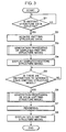
- FIG. 3 is a flowchart showing the main routine of the knitting structure model generating device.
- the knitting structure data is inputted by the user as he operates the input portion 30 (YES in S1), and the knitting structure data acquiring portion 11 acquires the knitting structure data inputted in the input portion 30.
- the flow returns to the processing in Step S1.
- FIG. 4 is a view schematically shows the knitting structure of a knit fabric.
- FIG. 4A shows the knitting structure formed of a knitting pattern of the knit alone.
- FIG. 4B shows the knitting structure in which a knitting pattern of the welt is aligned at the center.
- FIG. 4C shows the knitting structure in which a knitting pattern of the tuck is aligned at the center.
- the view in the top row shows the knitting structure when viewed from the front and the view in the bottom row shows the yarn in the second row in the top row when viewed from above.
- a yarn forming three loops in the first through third columns is aligned in three rows, and the loops in the second and third rows are connected to the loops in the first and second rows, respectively. It is therefore understood that the knitting pattern of the knit are aligned in an array of three rows x three columns. Also, the second column comes on the front and the first and third columns come on the back. Accordingly, as is shown in the bottom row in FIG. 4A , it is understood that the yarn in the second row is convex toward the front in the region corresponding to the loop in the second column, and this yarn is convex toward the back in regions corresponding to the loops in the first and third columns.
- a yarn forming three loops in the firs through third columns is aligned in the first and third rows
- a yarn forming two loops in the first and third columns is aligned in the second row
- the loop in the third row and in the second column is connected to the loop in the first row and in the second column.
- the knitting pattern of the welt is included.
- the second column comes on the front and the first and third columns come on the back. Accordingly as is shown in the bottom row in FIG. 4B , it is understood that the yarn in the second row is closed on the back in regions corresponding to the loops in the first and third columns and becomes flat along the back in the region corresponding to the loop in the second column.
- a yarn forming three loops in the first through third columns is aligned in three rows, and the loop formed in the third row and in the second column and the loop formed in the second row and in the second column are connected to the loop formed in the first row and in the second column.
- the knitting pattern of the tuck is included.
- the second column comes on the front and the first and third columns come on the back. Accordingly, as is shown in the bottom row in FIG. 4C , it is understood that the yarn in the third row is convex toward the back in regions corresponding to the loops in the first and third columns and this yarn is convex toward the front in the region corresponding to the loop in the second column.
- FIG. 5A through FIG. 5C are views showing the knitting structure data corresponding to FIG. 4A through FIG. 4C , respectively.
- the first and third columns represent the back and the second column represents the front and the knitting pattern of the knit is aligned in an array of three rows x three columns.
- a lower case "k" as the symbol is aligned in the first and third columns and an upper case “K” as the symbol is aligned in the second column.
- the first and third columns represent the back and the second column represents the second column and the knitting pattern of the welt is included in the second row and in the second column.
- FIG. 4C the first and third columns represent the back and the second column represents the second column.
- a lower case “k” is aligned in each row in the first and third columns and "K, T, and K" are aligned, respectively, in the first through third rows and in the second column.
- FIG. 4A through FIG. 4C show the knitting structure data for an array of three rows x three columns. It should be appreciated, however, that this configuration is a mere example and the number of rows and the number of columns can be changed as needed with the size of the knitting structure.
- Step S3 shown in FIG. 3 the node aligning portion 12 aligns the nodes within a specific plane and the simplified model generating portion 13 generates the simplified knitting structure model by connecting the aligned nodes and carrying out the generation processing of the simplified knitting structure model described below.
- Step S4 the display control portion 16 displays the knitting structure model generated by the simplified model generation portion 13 on the display portion 40.
- Step S5 in a case where an instruction to generate the solid knitting structure model is inputted in the input portion 30 by the user (YES in S5), the solid model generation portion 14 generates the solid knitting structure model from the simplified knitting structure model generated by the simplified model generating portion 13 (S6). Meanwhile, in a case where the instruction to generate the solid knitting structure model from the user is not accepted in the input portion 30 in Step S5 (NO in S5), the flow returns to the processing in Step S5.
- the display control portion 16 reads out the specified simplified knitting structure model from the simplified model storage portion 21 and displays this simplified knitting structure model on the display portion 40.
- Step S7 the rendering portion 15 renders the solid knitting structure model generated in Step S6, and the display control portion 16 displays the rendered solid knitting structure model on the display portion 40 (S8). It may be configured in such a manner that in a case where there is an input in the input portion 30 from the user to specify a solid knitting structure model generated by the solid state model generating portion 14 in the past, the display control portion 16 reads out the specified solid knitting structure model from the solid model storage portion 22 and displays this solid knitting structure model on the display portion 40.
- FIG. 6 is a flowchart showing the generation processing of the simplified knitting structure model shown in Step S3 in FIG. 3 .
- the node aligning portion 12 aligns the nodes in a lattice form within the XY plane in a virtual three-dimensional space according to the knitting structure data acquired by the knitting structure data acquiring portion 11.
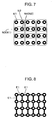
- FIG. 7 is a view showing the nodes aligned within the XY plane in a case where the knitting structure data is made up of an array of three rows x three columns.
- the node aligning portion 12 allocates four nodes to one symbol representing a knitting pattern. Of the four nodes allocated to each symbol, the node on the upper left is referred to as a first node N1, the node on the upper right is referred to as a second node N2, the node on the lower left is referred to as a third node N3, and the node on the lower right is referred to as a fourth node N4.
- the node aligning portion 12 aligns the respective nodes in such a manner that the third node N3 and the fourth node N4 allocated to a given symbol are aligned in common, respectively, with the first node N1 and the second node N2 allocated to another symbol present adjacently on the lower side of the firstly-mentioned symbol.
- the third node N3 and the fourth node N4 allocated to the symbol in the first row and in the first column are common, respectively, with the first node N1 and the second node N2 allocated to another symbol in the second row and in the first column.
- the node aligning portion 12 aligns four nodes in the longitudinal direction and six nodes, which is two times three that is the number of columns in the knitting structure data, in the lateral direction, and thereby aligns a total of 24 nodes within the XY plane.
- Four nodes are aligned in the longitudinal direction in FIG. 7 .
- nodes on the upper end are common with the nodes on the lower end, three nodes are aligned in the longitudinal direction in practice.
- the simplified model generating portion 13 connects the nodes adjacent to each other in the longitudinal direction with first edges and connects the nodes adjacent to each other in the lateral direction with the first edges.
- first edges are correlated with a first elastic constant used when stress acting on each node is calculated on the assumption that the node is a mass point of the knit fabric.
- second edges described below are correlated with a second elastic constant smaller than the first elastic constant.
- FIG. 8 is a view showing a state where the nodes are connected to one another. It is understood that, as is shown in FIG. 8 , the nodes adjacent to each other in the lateral direction and the nodes adjacent to each other in the longitudinal direction are connected with the first edges E1. It is also understood that two or three first edges E1 are connected to the nodes aligned on the upper end, the lower end, the left end, and the right end. Meanwhile, it is understood that four first edges E1 are connected to the nodes present inside.
- Step S13 shown in FIG. 6 the simplified model generating portion 13 makes the simplified knitting structure model in a torus shape by connecting the nodes positioned on the upper end and those on the lower end and connecting the nodes positioned on the left end and those on the right end.
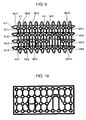
- FIG. 9 through FIG. 11 are views used to describe the processing in Step S13.
- the simplified model generating portion 13 connects the nodes NL1 through NL4 positioned on the left end to the nodes NR1 through NR4 positioned on the right end in the same rows with the first edges E1, and connects the node NU1 through NU10 positioned on the upper end and the nodes ND1 through ND10 positioned on the lower end in the same columns with the first edges E1.
- the simplified knitting structure model as is shown in FIG. 10 is a single knitting structure unit
- a simplified knitting structure model in which more than one knitting structure unit is aligned in a matrix fashion is generated, it becomes possible to express the entire region by aligning the nodes merely in a region of the knitting structure unit without having to align the nodes across the entire region of the simplified knitting structure model. It is therefore possible to markedly reduce a data volume of the simplified knitting structure model. This can be compared to an operation to deform a rectangular plane shown in FIG. 11A to a torus shape shown in FIG. 11B by connecting the upper edge and the lower edge and connecting the left edge and the right edge of this plane.
- Step S14 in a case where the knitting structure data acquired by the knitting structure data acquiring portion 11 includes only the knitting pattern of the knit and excludes the knitting patterns of the welt and the tuck (YES in S14), the simplified model generating portion 13 ends the processing because the simplified knitting structure model for the knitting structure data of interest is completed. Meanwhile, in a case where the knitting structure data includes the knitting pattern of the welt or the tuck in addition to that of the knit (NO in S14), the flow proceeds to the processing in Step S15.
- Step S15 in a case where the knitting structure data includes the knitting pattern of the tuck (YES in S15), the simplified model generating portion 13 carries out tuck processing described below for the nodes aligned within the XY plane (S16). The simplified knitting structure model having the knitting pattern of the tuck is thus generated. Meanwhile, in a case where the knitting pattern of the tuck is not included in Step S15 (NO in S15), the flow proceeds to the processing in Step S17.
- Step S17 in a case where the knitting structure data includes the knitting pattern of the welt (YES in S17), the simplified model generating portion 13 carries out welt processing described below (S18). The simplified knitting structure model having the knitting pattern of the welt is thus generated. Meanwhile, in a case where the knitting pattern of the welt is not included in Step S17 (NO in S17), the processing is ended by skipping the welt processing.
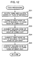
- FIG. 12 is a flowchart detailing the tuck processing shown in Step S16 of FIG. 6 .
- the simplified model generating portion 13 deletes the third node N3 and the fourth node N4 allocated to a tuck of interest, which is one tuck among the tucks making up the knitting structure data, and deletes the first edges E1 connected to each of the third node N3 and the fourth node N4.
- FIG. 13 is a view used to describe the processing in Step S21. It is understood that, as is shown in FIG. 13 , the third node N3 and the fourth node N4 allocated to the tuck T of interest are deleted while four first edges E1 connected to the third node N3 are deleted and four first edges E1 connected to the fourth node N4 are deleted.
- the simplified model generating portion 13 connects the first node N1 allocated to the tuck T of interest and the third node N3 allocated to a lower knit K present adjacently on the lower side of the tuck T with the first edge E1 (S22), and connects the second node N2 allocated to the tuck T of interest and the fourth node N4 allocated to the lower knit K with the first edge E1 (S23).
- the simplified model generating portion 13 connects the fourth node N4 of a left knit k present adjacently on the left side of the tuck T of interest and the first node N1 of the tuck T of interest with the first edge E1 (S24) and connects the third node N3 of a right knit k present adjacently on the right side of the tuck T of interest and the second node N2 of the tuck T of interest with the first edge E1 (S25).
- the simplified knitting structure model including the knitting pattern of the tuck T of interest as is shown in FIG. 14 is thus generated.
- the simplified model generating portion 13 carries out the processing described above repetitively using the symbol of each tuck included in the knitting structure data as the tuck of interest.
- FIG. 15 is a flowchart detailing the welt processing shown in Step S18 of FIG. 6 .
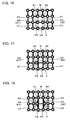
- FIG. 16 through FIG. 18 are views used to describe the welt processing.
- the welt processing will be described with reference to FIG. 16 through FIG. 18 .
- the simplified model generating portion 13 deletes the first edge E1 connecting the first node N1 and the third node N3 allocated to a welt W of interest, which is one welt among welts making up the knitting structure data (S31), and deletes the first edge E1 connecting the second node N2 and the fourth node N4 allocated to the welt W of interest (S32).
- the simplified model generating portion 13 deletes the first edge E1 connecting the first node N1 and the third node N3 allocated to the lower knit K present adjacently on the lower of the welt W of interest (S33) and deletes the first edge E1 connecting the second node N2 and the fourth node N4 allocated to the lower knit K (S34).
- the simplified model generating portion 13 connects the first node N1 allocated to the welt W of interest and the third node N3 allocated to the lower knit K present adjacently on the lower side with the first edge E1 (S35) and connects the second node N2 allocated to the welt W of interest and the fourth node N4 allocated to the lower knit K present adjacently on the lower side with the first edge E1 (S36).
- the third node N3 and the fourth node N4 of the welt W of interest are spaced apart widely in FIG. 17 and FIG. 18 . It should be appreciated, however, that the interval between the third node N3 and the fourth node N4 of the welt W of interest is equal to the interval shown in FIG. 16 in practice.
- the simplified model generating portion 13 connects the first node N1 and the third node N3 allocated to the welt W of interest with the second edge E2 and connects the second node N2 and the fourth node N4 allocated to the welt W of interest with the second edge E2 (S38).
- the simplified model generating portion 13 connects the first node N1 and the third node N3 allocated to the lower knit K with the second edge E2 and connects the second node N2 and the fourth node N4 allocated to the lower knit K with the second edge E2 (S39).
- the simplified model generating portion 13 carries out the processing described above using each of welts making up the knitting structure data as the welt of interest.
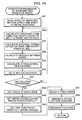
- FIG. 19 is a flowchart showing the generation processing of the solid knitting structure model.
- the solid model generating portion 14 places the simplified knitting structure model generated by the simplified model generating portion 13 on the XY plane and moves the respective nodes to specific initial positions.
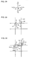
- FIG. 20 is a view showing the simplified knitting structure model made up of the knitting pattern of the knit in an array of three rows x three columns placed within a virtual three-dimensional space. As is shown in FIG. 20 , x, y, and z axes orthogonal to one another are set in the virtual three-dimensional space and the simplified knitting structure model is placed on the XY plane. Also, in FIG.
- the nodes placed on the first, second, fifth, and sixth columns from the left are nodes on the back, and the nodes aligned in the third and fourth columns from the left are nodes on the front.
- Each node on the back is slid by a certain distance in the -z direction and each node on the front is slid by a certain distance in the +z direction, so that each is moved to the specific initial position.
- a sliding amount of each node on the back and a sliding amount of each node on the front may be equal or set to different values.
- FIG. 21 is a view showing movements of the nodes of the welt W to the initial positions.
- FIG. 21A is a front view and FIG. 21B is a cross section when viewed from above. It is understood that, as are shown in FIG. 21A and FIG. 21B , the third node N3 and the fourth node N4 of the welt W are positioned on the XY plane because they are not slid in the Z direction. Also, because the first nodes N1 and N2 of the welt W are the nodes on the front, they are slid by a certain distance in the Z direction.
- the fourth node N4 of the knit K present adjacently on the left side and the third node N3 of the knit K present adjacently on the right side are slid by a certain distance in the -z direction because they are the nodes on the back.
- FIG. 22A is a view showing movements of the nodes of the tuck T to the initial values.
- FIG. 22A is a front view and FIG. 22B is a cross section when viewed from above.
- the first node N1 and the second node N2 of the tuck T are the nodes on the front and therefore slid by a specific distance in the z direction
- the fourth node N4 of the knit K present adjacently on the left side is a node on the back and is therefore slid by a specific distance in the -z direction
- the third node N3 of the knit K present adjacently on the right side is a node on the back and is therefore slid by a specific distance in the -z direction.
- the tuck T when viewed in the cross section is of a mountain shape same as the shape of the knit K when viewed in the cross section.
- Step S42 shown in FIG. 19 the solid model generating portion 14 calculates external forces acting on the third node N3 and the fourth node N4 of the welt W.
- FIG. 23 is a perspective view of nodes in the vicinity of the welt W when the processing in Step S42 through S47 is carried out repetitively to some extent.
- the solid model generating portion 14 calculates a distance between a rectangular plane defined by the first node N1 and the second node N2 of the welt W and the third node N3 and the fourth node N4 of the knit K present adjacently on the lower side of the welt W and the third node N3 as a distance between the third node N3 and the front of the solid knitting structure model. Subsequently, the solid model generating portion 14 calculates a distance between the rectangular plane and the fourth node N4 as a distance between the fourth node N4 and the front of the solid knitting structure model.
- the solid model generating portion 14 calculates a distance between a rectangular plane defined by the second node N2 and the fourth node N4 of the knit k present adjacently on the left side of the welt W and the first node N1 and the third node N3 of the knit k present adjacently on the right side of the welt W and the third node N3 as a distance between the third node N3 and the back of the solid knitting structure model. Subsequently, the solid model generating portion 14 calculates a distance between the fourth node N4 and the rectangular plane as a distance between the fourth node N4 and the back of the solid knitting structure model.
- Step S43 the solid model generating portion 14 finds external forces acting on each of the third nodes N3 and N4 of the welt W using the distances calculated in Step S42.
- F is an external force
- A is a constant
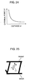
- d is a distance from the third node N3 or N4 of the welt W to the front or to the back of the solid knitting structure model.
- the external force is regulated by a function that is inversely proportional to the distance herein in order to reproduce a repulsive force induced when a yarn corresponding to the first edge E1 connecting the third node N3 and the fourth node N4 of the welt W comes into contact with a yarn corresponding to the first edge E1 connecting the first node N1 of the welt W and the third node N3 of the knit K on the lower side of the welt W.
- FIG. 25 is a view showing the side view of the solid knitting structure model shown in FIG. 24 in a simple manner.
- the upper edge of a rectangular frame represents the front of the solid knitting structure model and the lower edge represents the back of the solid knitting structure model and a circle positioned at the center inside the frame represents the first edge E1 connecting the third node N3 and the fourth node N4 of the welt W.
- Step S44 shown in FIG. 19 the solid model generating portion 14 calculates distances among the nodes connected to one another with the first edge E1 or the second edge E2 using Equations (1) through (4) below.
- the solid model generating portion 14 calculates a distance between the nodes positioned inside except for those on the end portions, that is, on the upper end, the lower end, the right side, and the left side, such as a node Ni1 and a node Ni2 shown in FIG. 9 , using Equation (1) above.
- dij is a distance between nodes Pi and Pj positioned inside
- xi, yi, zi are x, y, z components of Pi, respectively
- xj , yj , and zj are x, y, and z components of Pj , respectively.
- the solid model generating portion 14 calculates a distance between the nodes on the left side and the right side, such as a node NL2 and a node NR2 shown in FIG. 9 , using Equation (2) or (3) above. It should be noted, however, that in the case of xi > xj , a distance between the nodes is calculated using Equation (2) above and in the case of xi ⁇ xj, a distance between the nodes is calculated using Equation (3) above.
- the case of xi > xj referred to herein is a case where Pj is positioned on the left end and Pi is positioned on the right end in FIG. 9 .
- xi ⁇ xj a case where Pj is positioned on the right end and Pi is positioned on the left end in FIG. 9 .
- w is given as the initial value of a distance between a node on the left end of the simplified knitting structure model and another node positioned on the right end in the same row as the firstly mentioned node.
- xi - xj - w is given as the first term on the right side in Equation (2).
- the first term means that the position of the node Pj on the left end in the x direction is moved to a position found by adding w, which is the initial value of the crosswise width of the simplified knitting structure model, and a distance between the moved node and the node xi on the right end is calculated as a distance between the node on the left end and the node on the right end. Accordingly, a distance between the nodes connected by bridging from the left end to the right end is corrected to a size comparable to a distance between the nodes positioned adjacently inside. It is thus possible to generate a realistic solid knitting structure model that would otherwise look somewhat unnatural.
- the solid model generating portion 14 calculates a distance between nodes on the upper end and the lower end, such as nodes NU2 and ND2 shown in FIG. 9 , using Equations (4) and (5) below. It should be noted that in the case of yi > jy, a distance between nodes is calculated using Equation (4) below and in the case of yi ⁇ yj, a distance between nodes is calculated using Equation (5) below.
- the case of yi > yj referred to herein is a case where Pj is positioned on the upper end and Pi is positioned on the lower end in FIG. 9 .
- the case of yi ⁇ yj referred to herein is a case where Pj is positioned on the lower end and the Pi is positioned on the upper end in FIG. 9 .
- h is given as an initial value (initial value of the lengthwise width) of a distance between a node on the right end of the solid knitting structure model and another node positioned on the lower end and in the same column as the firstly-mentioned node.
- yi - yj - h is given as the second term in the right side in Equation (4) above.
- this term means that the position of the node Pj on the upper end in the y direction is moved to a position found by adding h, which is the initial value of the lengthwise width of the simplified knitting structure model, and a distance between the moved node and the node Pi on the lower end is calculated as a distance between the node on the upper end and the node on the lower end. Accordingly, a distance between the nodes connected by bridging from the upper end to the lower end is corrected to be almost the distance between the adjacent nodes positioned inside. It is thus possible to generate a realistic solid knitting structure model that would otherwise look somewhat unnatural.
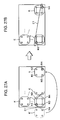
- the solid model generating portion 14 connects, as is shown in FIG. 26B , the second node N2 of the tuck T and the third node N3 of the knit K on the left end with the first edge E1 in a crossed fashion.
- the solid model generating portion 14 calculates a distance between the third node N3 of the knit K positioned on the left end and the second node N2 of the tuck T on the right end shown in FIG. 26B using Equation (7) or (8) below.
- a distance between the nodes Pi and Pj is calculated using Equation (7) above, and in a case where the node of the knit K on the left end is Pi and the second node N2 of the tuck T on the right end is Pj, a distance between the nodes Pi and Pj is calculated using Equation (8) above. Accordingly, a distance between the nodes Pi and Pj is corrected to be almost the distance between the nodes positioned inside. It is thus possible to generate a realistic solid knitting structure model that would otherwise look somewhat unnatural.
- the solid model generating portion 14 connects, as is shown in FIG. 27B , the first node N1 of the tuck T and the fourth node N4 of the knit K with the first edge E1 in a crossed fashion.
- the solid model generating portion 14 calculates a distance between the fourth node N4 of the knit K positioned on the right end and the first node N1 of the tuck T on the right end shown in FIG. 27B using Equation (6) or (9) above.
- a distance between the nodes Pi and Pj is calculated using Equation (6) above, and in a case where the first node N1 of the tuck T on the left end is the node Pi and the fourth node N4 of the knit K on the right end is the node Pj, a distance between the nodes Pi and Pj is calculated using Equation (9) above. Accordingly, the nodes Pi and Pj are corrected to have a distance almost equal to the distance between the nodes positioned inside. It is thus possible to generate a realistic solid knitting structure model that would otherwise look somewhat unnatural.
- Step S45 shown in FIG. 19 the solid model generating portion 14 calculates stress acting on the respective nodes using distances among the respective nodes calculated in Step S44.
- the solid model generating portion 14 calculates the second and third terms on the right side of Equation (10) below as the stress.
- Equation (11) the third term in Equation (10) below can be expressed as Equation (11) below.
- Pi is a node to which a motion equation is applied
- Pj is another node connected to Pi
- mi is the mass of the node Pi
- ci is viscous resistance of Pi
- kij is a visco-elastic constant
- vi is the velocity of the node Pi.
- Pi, Pj, vi, and fi are vectors made up of three components including x, y, and z.
- P i k i ⁇ 1 ⁇ P i - P 1 P i - P 1 + k i ⁇ 2 ⁇ P i - P 2 P i - P 2 + k i ⁇ 3 ⁇ P i - P 3 P i - P 3 + k i ⁇ 4 ⁇ P i - P 4 P i - P 4
- first elastic constants are correlated with the first edge E1 and the second elastic constant is correlated with the second edge E2.
- the solid model generating portion 14 calculates the second term in Equation (10) above by multiplying the velocity vi of the node Pi, which is obtained by solving the motion equation expressed by Equation (10) above, by the viscous resistance ci.
- the viscous resistance ci may adopt the same value for all the nodes or may be changed depending on how many first edges and second edges are connected to each node.
- Step S46 shown in FIG. 19 the solid model generating portion 14 calculates the position and the velocity of each node Pi by solving the motion equation expressed by Equation (10) above that is established for each node Pi.
- Equation (10) fi in the left side of Equation (10) is an external force acting on each node Pi that is calculated in Step S43.
- mi is the mass at the mass point of the knit fabric.
- the value of mi may adopt the same value for all the nodes or may adopt different values.
- the value adopted for mi is the value determined preliminarily from the relation of the kind of the knit fabric and the size and the number of nodes of the knit fabric when the knit fabric is represented by nodes.
- the solid model generating portion 14 solves the motion equation for each node using Equation (12) below expressing a differential equation of the motion equation expressed by Equation (10) above.
- t is the time and ⁇ t is a nick of time.
- Step S47 the solid model generating portion 14 determines whether the solution of the motion equation expressed by Equation (12) converges within a specific range. In a case where it is determined that the solution has converged (YES in S47), the flow proceeds to the processing in Step S48. In a case where it is determined that the solution has not converged (NO in S47), the flow returns to the processing in Step S42. In short, the motion equation is calculated repetitively until the solution of the motion equation expressed by Equation (12) converges.
- the phrase, "the solution of the motion equation converges", referred to herein corresponds to a case where a difference between the latest solution and the solution calculated last time becomes smaller than a specific value for Pi indicating the position or vi indicating the velocity of each node in Equation (12). Alternatively, it may be determined that the solution has converged when the motion equation is calculated a predetermined number of times.
- Step S48 the solid model generating portion 14 sets a circle used to set a yarn to the solid knitting structure model along the edges connected to the respective nodes.
- a circle C1 having a specific radius is set in such a manner that the circumference passes through the node Pi and the center O1 is positioned on the edges EA and EB side.
- a circle C2 having a specific radius is set in such a manner that the circumference passes through the node Pj and the center 02 is positioned on the edges EB and EC side.
- values preliminarily determined in response to the physical property of the yarns are adopted as the radii of the circles C1 and C2, and either a value that varies from node to node or the same value is adopted.
- Step S49 the solid model generating portion 14 sets circles having radii larger than the radii set for the circles at the respective nodes concentrically.
- a circle C3 having a radius larger than that of the circle C1 set at the node Pi is set concentrically
- a circle C4 having a radius larger than that of the circle C2 set at the node Pj is set concentrically.
- Step S50 shown in FIG. 19 the solid model generating portion 14 sets two lines smoothly linking every two circles set at the respective nodes as yarn paths.
- a yarn path P R (k) smoothly linking the circle C1 and the circle C4 and a yarn path P L (k) smoothly linking the circle C3 and the circle C2 are set.
- P R (k) and P L (k) are a parameter representing the yarn path and the domain thereof is expressed as - ⁇ ⁇ k ⁇ ⁇ .
- Step S51 the solid model generating portion 14 carries out processing to smooth the two yarn paths that have been set.
- the solid model generating portion 14 calculates a first-order term found when a function (original function) representing the each yarn path that has been set is expanded by a Fourier series, and then smoothes the original function by expanding a function, which is found by subtracting the calculated first-order term from the original function, by a Fourier series to a lower-order (for example, third-order term) term.
- the solid model generating portion 14 isolates the original function to three components, x, y, and z, and carries out the processing described above for each component.
- x(k) is given as the x component of the original function.
- the solid model generating portion 14 calculates x1 (t), which is the first-order term when x(k) is expanded by a Fourier series.
- x1(k) ((x( ⁇ ) - x(- ⁇ ))/2 ⁇ ) ⁇ k + x(- ⁇ ).
- the first-order term is added. In this manner, x(k) is smoothed.
- the knitting structure model generating device makes the x component continuous by adding the first-order term after to x(k) - x1(k) is expanded by a Fourier series.
- Step S52 shown in FIG. 19 the solid model generating portion 14 finds a circle having a straight line linking the end points of the smoothed two yarn paths as a diameter to be the yarn cross section.
- a circle having a diameter from P L (k) representing a given point on one of the two yarn paths to P R (k) representing a given point on the other yarn path where k is the same is found as the yarn cross section.
- plural yarn cross sections are calculated by varying the value of k by a constant stride ⁇ k to generate a yarn cross section sequence.
- Equation (13) P(k) specifying one point on the circumference of the yarn cross section
- P k P L k - P R k ⁇ A ⁇ cos ⁇ + P L k - P R k ⁇ ⁇ P L k - P R k ⁇ C ⁇ P L k - P R k 2 ⁇ B ⁇ sin ⁇ + P L k + P R k 2
- the first term, (P L (k) - P R (k))/2 is a base vector A representing the radius of the yarn cross section as is shown in FIG. 31 .
- the second term, (P L (k) - P R (k))'/(P L (k) - P R (k)), is a derivative value with respect to k of the unit vector in the diameter direction and represents the vector C that specifies the yarn direction.
- the coefficient of sin ⁇ in the second term is the vector product of the vector C and the base vector A and represents a base vector B on the yarn cross section.
- ⁇ is a variable used to express the circumference of the yarn cross section using the base vectors A and B.
- the third term, (P L (k) + P R (k))/2 represents the center O of the yarn cross section.
- Step S53 shown in FIG. 19 the solid model generating portion 14 connects the circumferences in the yarn cross section sequence with polygons and sets the circumferential surface of the yarn into the solid knitting structure model.
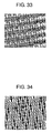
- FIG. 32 is a view showing the rendering result of the solid knitting structure model generated by the solid model generating portion 14. It is understood that, as is shown in FIG. 32 , a myriad of yarns are knitted according to the knitting patterns.
- FIG. 33 is a view showing the solid knitting structure model when the knitting structure model shown in FIG. 32 is shown in a reduced scale. It is understood that, as is shown in FIG. 33 , a realistic solid knitting structure model is generated by carrying out the processing described above.
- FIG. 34 is a view showing the rendering result of the solid knitting structure model including the knitting pattern of the tuck. It is understood that, as is shown in FIG. 34 , because two yarns are connected at the first node N1 and the second node N2 according to the knitting pattern of the tuck, a force that narrows the width between the first node N1 and the second node N2 is induced as is indicated by arrows, which consequently generates a solid knitting structure model having many pores.
- the simplified knitting structure model is generated by acquiring the knitting structure data of yarns and connecting the nodes aligned within the XY plane according to the knitting structure data with the edges corresponding to yarns and displayed on the display portion 40.
- a solid knitting structure model of the knit fabric is generated by solving the motion equation for each node on the assumption that each node is a mass point of the knit fabric by letting stress corresponding to the kinds of the edges connected to each node act and applying a specific external force on each node. It is therefore possible to obtain the solid knitting structure model that includes and considers the mechanical characteristic of the knit fabric.
- the embodiment above is configured in such a manner that the simplified knitting structure is displayed on the display portion 40. It should be appreciated, however, that the invention is not limited to this configuration.
- the simplified knitting structure model may be printed on a recoding sheet using output means, such as a printer.
- output means such as a printer.
- a knit fabric of double sided knitting is adopted in the embodiment above.
- the invention is not limited to this example, and the invention is also applicable to a knit fabric of single side knitting.
- the lower knit K is adjacent to the tuck T of interest in FIG. 13 and other relevant drawings.
- the lower knit K is not necessarily an adjacent node and a knit positioned in the same column and on the lower side of the tuck T of interest may be adopted as the lower knit.
- a computer-readable recording medium which stores a knitting structure model generating program is a knitting structure model generating program for generating a knitting structure model of a knit fabric within a virtual three-dimensional space, said program causing a computer to function as at least: knitting structure data acquiring means for acquiring knitting structure data in which a knitting structure of the knit fabric is represented by symbols corresponding to knitting patterns making up the knitting structure; node aligning means for aligning nodes representing connecting points of yarns forming the knit fabric in a lattice form on a specific plane within the virtual three-dimensional space; and simplified model generating means for generating a simplified knitting structure model that represents the knit fabric in a simplified manner by connecting the nodes aligned within the virtual three-dimensional space with edges corresponding to the yarns according to the knitting structure data acquired by the knitting structure data acquiring means.
- a kitting structure model generating device is a knitting structure model generating device that generates a knitting structure model of a knit fabric within a virtual three-dimensional space, including: a knitting structure data acquiring means for acquiring knitting structure data in which a knitting structure of the knit fabric is represented by symbols corresponding to knitting patterns making up the knitting structure; node aligning means for aligning nodes representing connecting points of yarns forming the knit fabric in a lattice form on a specific plane within the virtual three-dimensional space; and a simplified model generating means for generating a simplified knitting structure model by connecting the nodes aligned within the virtual three-dimensional space with edges corresponding to the yarns according to the knitting structure data acquired by the knitting structure data acquiring means.
- a knitting structure model generating method is a knitting structure model generating method of generating a knitting structure model of a knit fabric within a virtual three-dimensional space, said method comprising the steps of: obtaining knitting structure data by a computer in which a knitting structure of the knit fabric is represented by symbols corresponding to knitting patterns making up the knitting structure ; aligning by the computer nodes representing connecting points of yarns forming the knit fabric in a lattice form on a specific plane within the virtual three-dimensional space; and generating by the computer a simplified knitting structure model by connecting the nodes aligned within the virtual three-dimensional space with edges representing connection relations among the nodes according to the knitting structure data that has been acquired.
- a simplified knitting structure model is generated by obtaining the knitting structure data in which the knitting patterns are represented by specific symbols and connecting the nodes aligned within the specific plane in the virtual three-dimensional space with the edges corresponding to the yarns according to the knitting structure data.
- the knitting structure data has a data structure in which the symbols corresponding to the knitting patterns are aligned in a matrix fashion; the node aligning means allocates four nodes adjacent to each other in a lattice form to each symbol; the four nodes allocated to each symbol includes a first node positioned on an upper left, a second node positioned on an upper right, a third node positioned on a lower left, and a fourth node positioned on a lower right; and the third and fourth nodes allocated to a symbol of interest, which is one symbol to be of interest among the symbols representing the knitting patterns making up the knitting structure data, are common, respectively, with the first and second nodes allocated to another symbol present adjacently on a lower side of the symbol of interest.
- the first through fourth nodes that are positioned adjacently on the upper left, the upper right, the lower left, and the lower right in a lattice form are allocated to each symbol.
- the respective nodes are aligned in such a manner that the third and fourth nodes allocated to a given symbol are common, respectively, with the first and second nodes allocated to another symbol present adjacently on the lower side of the firstly-mentioned symbol. Accordingly, for example, when two edges are connected to a node, it is possible to express that two yarns are connected to this node.
- the knitting structure data includes a knitting pattern of a knit
- the simplified model generating means generates the simplified knitting structure model by connecting the nodes adjacent to each other in a longitudinal direction and in a lateral direction with the edges.
- the knitting structure data includes knitting patterns of a knit and a tuck and a left knit symbol representing the knitting pattern of the knit is present adjacently on a left side of a tuck symbol of interest, which is one tuck symbol to be of interest among the knitting patterns making up the knitting structure data, a right knit symbol representing the knitting pattern of the knit is present adjacently on a right side of the tuck symbol of interest, and a lower knit symbol representing the knitting pattern of the knit is present on a lower side of the tuck symbol of interest, and that the simplified model generating means carries out processing as follows using the symbol of each tuck as the tuck symbol of interest: connecting the nodes present adjacently to each other in a longitudinal direction and in a lateral direction with the edges; deleting the third and fourth nodes allocated to the tuck symbol of interest and the edges connected to the third and fourth nodes; connecting the first node and the second node allocated to the tuck symbol of interest with two edges
- the edges include a first edge representing first stress acting on each node and a second edge representing second stress weaker than the first stress
- the knitting structure data includes knitting patterns of a knit and a welt
- a lower knit symbol representing the knitting pattern of the knit is present adjacently on a lower side of a welt symbol of interest, which is one welt symbol to be of interest among the symbols making up the knitting structure data
- the simplified model generating means carries out processing as follows using each welt symbol as the welt symbol of interest: connecting the nodes present adjacently to each other in a longitudinal direction and in a lateral direction with the first edges; deleting the first edges connecting the first and third nodes as well as the second and fourth nodes allocated to the welt symbol of interest, and deleting the first edges connecting the first and third nodes as well as the second and fourth nodes allocated to the lower knit symbol; connecting the first and third nodes allocated to the welt symbol of interest with the second edge and connecting the second and fourth nodes allocated to the lower knit symbol; connecting the first and third nodes allocated to
- the simplified model generating means generates the simplified knitting structure model by connecting each node positioned on a left end and a node positioned on a right end in a same row and connecting each node positioned on an upper end and a node positioned on a lower end in a same column.
- the nodes represent mass points of the knit fabric; the edges represent stress acting on the mass points; and the knitting structure model generating program causes the computer to function further as solid model generating means for generating a solid knitting structure model by solving a motion equation of each node by finding stress acting on each node on a basis of the edges making up the simplified knitting structure model generated by the simplified model generating means and applying a specific external force on each node in a direction crossing an alignment plane of each node.
- the solid knitting structure model of the knit fabric is generated by solving the motion equation of each node on the assumption that each node is the mass point of the knit fabric by letting stress corresponding to the kinds of the edges connected to each node act and applying a specific external force on each node. It is thus possible to obtain the solid knitting structure model that includes and considers the mechanical characteristic of the knit fabric.
- the specific external force acts in a direction crossing the alignment plane of the node, the node is allowed to move with ease in the direction crossing the alignment plane, which makes it possible to express the knitting patterns of yarns better in a solid form.
- the knit fabric is a knit fabric of double sided knitting formed of a front and a back
- the solid model generating means causes a repulsive force, which is inversely proportional to a distance to the front and a distance to the back from each of the third and fourth nodes allocated to a symbol of a welt, to act on each of the third and fourth nodes as the external force.
- the solid model generating means sets two circles having different radii at each node concentrically, and sets two lines smoothly connecting the two circles set at a node of interest and the two circles set at another node connected to the node of interest with the edge as yarn paths.
- the solid model generating means smoothes the yarn paths by subtracting a first-order term when an original function representing each yarn path is expanded by a Fourier series from the original function, expanding a function after subtraction by a Fourier series to a specific lower-order term, and adding the first-order term.
- the first-order term is subtracted from the original function, and the function after subtraction is expanded by a Fourier series to a lower-order term, after which the first-order term is added. It is thus possible to set smoother yarns to the solid knitting structure model while maintaining continuity.
- a computer-readable recording medium which stores a knitting structure model generating program according to fourth aspect of the invention is a knitting structure model generating program for generating a knitting structure model of a knit fabric within a virtual three-dimensional space, causing a computer to function as at least: simplified model obtaining means for obtaining a simplified knitting structure model in which nodes representing connecting points of yarns forming the knit fabric are aligned in a lattice form on a specific plane within the virtual three-dimensional space and the respective nodes are connected with edges corresponding to the yarns; and solid model generating means for generating a solid knitting structure model by solving a motion equation of each node by finding stress acting on each node making up the simplified knitting structure model on a basis of the edges making up the simplified knitting structure model obtained by the simplified knitting structure model obtaining means and applying a specific external force on each node in a direction crossing an alignment plane of each node.
- a knitting structure model generating device is a knitting structure model generating device that generates a knitting structure model of a knit fabric within a virtual three-dimensional space, including: a simplified model obtaining means for obtaining a simplified knitting structure model in which nodes representing connecting points of yarns forming the knit fabric are aligned in a lattice form on a specific plane within the virtual three-dimensional space and the respective nodes are connected with edges corresponding to the yarns; and a solid model generating means for generating a solid knitting structure model by solving a motion equation of each node by finding stress acting on each node on a basis of the edges making up the simplified knitting structure model obtained by the simplified knitting structure model obtaining means and applying a specific external force on each node in a direction crossing an alignment plane of each node.
- a knitting structure model generating method is a knitting structure model generating method of generating a knitting structure model of a knit fabric within a virtual three-dimensional space, said method comprising the steps of: obtaining by a computer_a simplified knitting structure model, in which nodes representing connecting points of yarns forming the knit fabric are aligned in a lattice form on a specific plane within the virtual three-dimensional space and the respective nodes are connected with edges corresponding to the yarns; and generating by the computer a solid knitting structure model by solving a motion equation acting on each node by finding stress acting on each node of the simplified knitting structure model on a basis of the edges making up the simplified knitting structure model-and applying a specific external force on each node in a direction crossing an alignment plane of each node.
- the solid knitting structure model of the knit fabric is generated by solving the motion equation of each node on the assumption that each node is the mass point of the knit fabric by letting stress corresponding to the kinds of the edges connected to each node act and applying a specific external force on each node. It is thus possible to obtain the solid knitting structure model that includes and considers the mechanical characteristic of the knit fabric.
- the specific external force acts in a direction crossing the alignment plane of the node, the node is allowed to move with ease in the direction crossing the alignment plane, which makes it possible to express the knitting patterns of yarns better in a solid form.
Landscapes
- Engineering & Computer Science (AREA)
- Physics & Mathematics (AREA)
- Theoretical Computer Science (AREA)
- General Physics & Mathematics (AREA)
- Geometry (AREA)
- Software Systems (AREA)
- Computer Graphics (AREA)
- Computer Hardware Design (AREA)
- Evolutionary Computation (AREA)
- General Engineering & Computer Science (AREA)
- Knitting Machines (AREA)
- Image Generation (AREA)
- Processing Or Creating Images (AREA)
Claims (10)
- Ein computerlesbares Aufzeichnungsmedium (8), das ein Strickstrukturmodell generierendes Programm speichert, zur Erzeugung eines Strickstrukturmodells eines Gestricks innerhalb eines virtuellen dreidimensionalen Raums, wobei das genannte Programm bewirkt, dass ein Computer zumindest als eines der Folgenden funktioniert:Strickstrukturdaten-Erfassungsmittel (11) zur Erfassung von Strickstrukturdaten, in denen eine Strickstruktur eines Gestricks durch Symbole dargestellt wird, die Strickmustern entsprechen, die die Strickstruktur ausmachen;Knotenausrichtungsmittel (12) zur Ausrichtung von Knoten (N, P), die Verbindungspunkte von Garnen darstellen, die das Gestrick in Gitterform auf einer spezifischen Ebene innerhalb des virtuellen dreidimensionalen Raums bilden; undMittel (13) zur Erzeugung eines vereinfachten Modells, zur Erzeugung eines vereinfachten Strickstrukturmodells, das das Gestrick auf vereinfachte Weise durch die Verbindung der innerhalb des virtuellen dreidimensionalen Raums ausgerichteten Knoten (N, P) darstellt, mit Kanten (E), die den Garnen der durch die Strickstrukturdaten-Erfassungsmittel (11) erfassten Strickstrukturdaten entsprechen, wobei:die Knoten (N, P) Massenpunkte des Gestricks darstellen;die Kanten (E) Beanspruchungen darstellen, die auf die Massenpunkte wirken; und wobeidas Strickstrukturmodell generierende Programm den Computer dazu veranlasst des Weiteren als Mittel (14) zur Erzeugung eines Volumenmodells zu funktionieren, zur Erzeugung eines räumlichen Strickstrukturmodells durch die Lösung einer Bewegungsgleichung eines jeden Knotens (N, P), indem es die Beanspruchungen findet, die auf jeden Knoten (N, P) wirken, der das vereinfachte Strickstrukturmodell ausmacht auf der Basis der Kanten (E), die das vereinfachte Strickstrukturmodell ausmachen, das durch das Mittel (13) zur Erzeugung eines vereinfachten Modells erzeugt wird, und indem es eine spezifische äußere Kraft (f) an jeden Knoten (N, P) in eine Richtung anlegt, die eine Ausrichtungsebene eines jeden Knotens (N, P) kreuzt,und wobeidas Mittel (14) zur Erzeugung eines Volumenmodells zwei Kreise (C) setzt, die an jedem Knoten (N, P) auf konzentrische Weise verschiedene Radien aufweisen, und zwei Linien setzt, die die am betreffenden Knoten (N, P) gesetzten zwei Kreise (C) und die an einem anderen Knoten (N, P) gesetzten zwei Kreise (C) straff verbinden, wobei der letztere Knoten mit dem betreffenden Knoten (N, P) mit den Kanten (E) als Fadenlauf verbunden ist.
- Das computerlesbares Aufzeichnungsmedium (8) nach Anspruch 1, wobei:die Strickstrukturdaten eine Datenstruktur aufweisen, bei der die den Strickmustern entsprechenden Symbole in Art einer Matrix ausgerichtet sind;das Knotenausrichtungsmittel (12) jedem Symbol vier in Gitterform benachbart zueinander liegende Knoten (N, P) zuordnet;die jedem Symbol zuordneten vier Knoten (N, P) beinhaltet: einen ersten Knoten, der oben links angeordnet ist, einen zweiten Knoten, der oben rechts angeordnet ist, einen dritten Knoten, der unten links angeordnet ist, und einen vierten Knoten, der unten rechts angeordnet ist; undder dritte und vierte Knoten, die einem betreffenden Symbol zugeordnet sind, welches ein Symbol von Interesse ist unter den das Strickmuster darstellenden Symbolen, die die Strickstrukturdaten ausmachen, jeweils gemeinsam sind (are common) mit dem ersten und zweiten Knoten, die einem anderen Symbol zugeordnet sind, das sich an einer unteren Seite des betreffenden Symbols anschließend befindet.
- Das computerlesbares Aufzeichnungsmedium (8) nach Anspruch 2, wobei:die Strickstrukturdaten ein Strickmuster eines Stricks bzw. einer Strickmasche bzw. eines Strickvorgangs (knit) umfassen; unddas Mittel (13) zur Erzeugung eines vereinfachten Modells das vereinfachte Strickstrukturmodell erzeugt, indem die in longitudinaler und in seitlicher Richtung aneinander angrenzenden Knoten (N, P) mit den Kanten (E) verbunden werden.
- Das computerlesbares Aufzeichnungsmedium (8) nach Anspruch 2, wobei:die Strickstrukturdaten Strickmuster eines Stricks bzw. einer Strickmasche bzw. eines Strickvorgangs (knit) (K, k) und eines Fangs bzw. einer Fangmasche bzw. eines Fangvorgangs (tuck) (T, t) umfassen; und wobeiein linkes Stricksymbol (left knit symbol), das das Strickmuster des Strickvorgangs darstellt, angrenzend an einer linken Seite eines betreffenden Fangsymbols vorhanden ist, das ein Fangsymbol von Interesse sein kann unter den Strickmustern, die die Strickstrukturdaten ausmachen, ein rechtes Stricksymbol (right knit symbol), das das Strickmuster des Strickvorgangs darstellt, angrenzend an einer rechten Seite eines betreffenden Fangsymbols vorhanden ist, und ein unteres Stricksymbol (lower knit symbol), das das Strickmuster des Strickvorgangs darstellt, angrenzend an einer unteren Seite eines betreffenden Fangsymbols vorhanden ist, und wobei das Mittel (13) zur Erzeugung eines vereinfachten Modells die Verarbeitung (processing) wie folgt durchführt, indem das Symbol für jeden Fangvorgang (T, t) als das Fangsymbol von Interesse verwendet wird:verbinden der in longitudinaler und in seitlicher Richtung aneinander angrenzend anwesenden Knoten (N, P) mit den Kanten (E);löschen der dem betreffenden Fangsymbol zugeordneten dritten und vierten Knoten und der mit den dritten und vierten Knoten verbundenen Kanten (E);verbinden des dem betreffenden Fangsymbol zugeordneten ersten und zweiten Knotens mit zwei Kanten (E);verbinden des dem betreffenden Fangsymbol zugeordneten ersten Knotens und des dem unteren Stricksymbol (K) zugeordneten dritten Knotens mit der Kante (E), und verbinden des dem betreffenden Fangsymbol zugeordneten zweiten Knotens und des dem unteren Stricksymbol zugeordneten vierten Knotens mit der Kante (E); undverbinden des dem linken Stricksymbol zugeordneten vierten Knotens und des dem betreffenden Fangsymbol zugeordneten ersten Knotens mit der Kante (E), und verbinden des dem rechten Stricksymbol zugeordneten dritten Knotens und des dem betreffenden Fangsymbol zugeordneten zweiten Knotens mit der Kante (E).
- Das computerlesbares Aufzeichnungsmedium (8) nach Anspruch 2, wobei:die Kanten (E) eine erste Kante beinhalten, die eine erste Beanspruchung darstellt, die auf jeden Knoten (N, P) wirkt, und eine zweite Kante beinhalten, die eine zweite Beanspruchung darstellt, die geringer als die erste Beanspruchung ist;die Strickstrukturdaten Strickmuster eines Strickvorgangs (K, k) und eines Nichtstrickvorgangs (welt) (W, w) umfassen; undein unteres Stricksymbol (lower knit symbol), das das Strickmuster des Strickvorgangs darstellt, angrenzend, an einer unteren Seite eines betreffenden Nichtstricksymbols vorhanden ist, welches ein Nichtstricksymbol von Interesse sein kann unter den Strickmustern, die die Strickstrukturdaten ausmachen, und wobei das Mittel (13) zur Erzeugung eines vereinfachten Modells die Verarbeitung wie folgt durchführt, indem jedes Nichtstricksymbol als das Nichtstricksymbol von Interesse verwendet wird:verbinden der in longitudinaler und seitlicher Richtung aneinander angrenzenden Knoten (N, P) mit den ersten Kanten;löschen der ersten Kanten, die den ersten und dritten Knoten verbinden wie auch der zweiten und vierten Knoten, die dem betreffenden Nichtstricksymbol zugeordnet sind, und löschen der ersten Kanten, die die ersten und dritten Knoten verbinden wie auch der zweiten und vierten Knoten, die dem unteren Stricksymbol zugeordnet sind;verbinden der ersten und dritten Knoten, die dem betreffenden Nichtstricksymbol zugeordnet sind, mit der zweiten Kante und verbinden der zweiten und vierten Knoten, die dem betreffenden Nichtstricksymbol zugeordnet sind, mit der zweiten Kante;verbinden der ersten und dritten Knoten, die dem unteren Stricksymbol zugeordnet sind, mit der zweiten Kante, und verbinden der zweiten und vierten Knoten, die dem unteren Stricksymbol zugeordnet sind, mit der zweiten Kante; undverbinden des ersten Knotens, der dem betreffenden Nichtstricksymbol zugeordnet ist, und des dritten Knotens, der dem unteren Stricksymbol zugeordnet ist, mit der ersten Kante, und verbinden des zweiten Knotens, der dem betreffenden Nichtstricksymbol zugeordnet ist, und des vierten Knotens, der dem unteren Stricksymbol zugeordnet ist, mit der ersten Kante.
- Das computerlesbares Aufzeichnungsmedium (8) nach einem der Ansprüche von 1 bis 5, wobei:das Mittel (13) zur Erzeugung eines vereinfachten Modells das vereinfachte Strickstrukturmodell erzeugt, indem jeder an einem linken Ende positionierter Knoten (N, P) und ein an einem rechten Ende einer selben Reihe positionierter Knoten (N, P) verbunden werden und indem jeder an einem oberen Ende positionierter Knoten (N, P) und ein an einem unteren Ende einer selben Spalte positionierter Knoten (N, P) verbunden werden.
- Das computerlesbares Aufzeichnungsmedium (8) nach einem der Ansprüche von 1 bis 6, wobei:das Gestrick ein doppelseitiges Gestrick ist, das aus einer Vorderseite und einer Rückseite besteht; und wobeidas Mittel (14) zur Erzeugung eines Volumenmodells eine Abstoßungskraft verursacht, die umgekehrt proportional zu einem Abstand zur Vorderseite und einem Abstand zur Rückseite ist, ausgehend von jedem der dritten und vierten Knoten, die einem Nichtstricksymbol (W, w) zugeordnet sind, um auf jeden der dritten und vierten Knoten als äußere Kraft (f) zu wirken.
- Das computerlesbares Aufzeichnungsmedium (8) nach einem der Ansprüche von 1 bis 7, wobei:das Mittel (14) zur Erzeugung eines Volumenmodells die Fadenläufe glättet, durch subtrahieren eines Glieds erster Ordnung, wenn eine ursprüngliche Funktion, die jeden Fadenlauf darstellt, durch eine Fourierreihe der ursprünglichen Funktion erweitert wird, erweitern einer Funktion, nach der Subtraktion, durch eine Fourierreihe zu einem spezifischen Glied niederer Ordnung, und addieren des Glieds erster Ordnung.
- Eine Strickstrukturmodell erzeugende Vorrichtung, die ein Strickstrukturmodell eines Gestricks innerhalb eines virtuellen dreidimensionalen Raums erzeugt, die Folgendes umfasst:ein Strickstrukturdaten-Erfassungsmittel (11), zur Erfassung von Strickstrukturdaten, in denen eine Strickstruktur eines Gestricks durch Symbole dargestellt wird, die Strickmustern entsprechen, die die Strickstruktur ausmachen;ein Knotenausrichtungsmittel (12), zur Ausrichtung von Knoten (N, P), die Verbindungspunkte von Garnen darstellen, die das Gestrick in Gitterform auf einer spezifischen Ebene innerhalb des virtuellen dreidimensionalen Raums bilden; undein Mittel (13) zur Erzeugung eines vereinfachten Modells, zur Erzeugung eines vereinfachten Strickstrukturmodells, indem die im virtuellen dreidimensionalen Raums ausgerichteten Knoten (N, P) mit Kanten (E) verbunden werden, die den Garnen gemäß den durch die Strickstrukturdaten-Erfassungsmittel (11) erfassten Strickstrukturdaten entsprechen, wobei:die Knoten (N, P) Massenpunkte des Gestricks darstellen;die Kanten (E) Beanspruchungen darstellen, die auf die Massenpunkte wirken; und wobeidie Strickstrukturmodell generierende Vorrichtung des Weiteren ein Mittel (14) zur Erzeugung eines Volumenmodells umfasst, zur Erzeugung eines räumlichen Strickstrukturmodells durch die Lösung einer Bewegungsgleichung eines jeden Knotens (N, P), indem die Beanspruchung gefunden wird, die auf jeden das vereinfachte Strickstrukturmodell ausmachenden Knoten (N, P) wirkt, aufgrund der Kanten (E), die das durch das Mittel (13) zur Erzeugung eines vereinfachten Modells erzeugte vereinfachte Strickstrukturmodell ausmachen und indem eine spezifische äußere Kraft (f) an jeden Knoten (N, P) in eine Richtung anlegt wird, die eine Ausrichtungsebene eines jeden Knotens (N, P) kreuzt, und wobeidas Mittel (14) zur Erzeugung eines Volumenmodells zwei Kreise (C) setzt, die an jedem Knoten (N, P) auf konzentrische Weise verschiedene Radien aufweisen, und zwei Linien setzt, die die am betreffenden Knoten (N, P) gesetzten zwei Kreise (C) und die an einem anderen Knoten (N, P) gesetzten zwei Kreise (C) straff verbinden, wobei der letztere Knoten mit dem betreffenden Knoten (N, P) mit den Kanten (E) als Fadenlauf verbunden ist.
- Ein Strickstrukturmodell erzeugendes Verfahren zur Erzeugung eines Strickstrukturmodells eines Gestricks innerhalb eines virtuellen dreidimensionalen Raums erzeugt, wobei das genannte Verfahren die folgenden Schritte umfasst:erlangen von Strickstrukturdaten durch einen Computer, in denen eine Strickstruktur eines Gestricks durch Symbole dargestellt wird, die Strickmustern entsprechen, die die Strickstruktur ausmachen;ausrichten durch den Computer von Knoten (N, P), die Verbindungspunkte von Garnen darstellen, die das Gestrick in Gitterform auf einer spezifischen Ebene innerhalb des virtuellen dreidimensionalen Raums bilden; underzeugen durch den Computer eines vereinfachten Strickstrukturmodells, indem die im virtuellen dreidimensionalen Raums ausgerichteten Knoten (N, P) mit Kanten (E) verbunden werden, die Verbindungszusammenhänge zwischen den Knoten (N, P) darstellen, gemäß den Strickstrukturdaten, die erfasst worden sind, wobei:die Knoten (N, P) Massenpunkte des Gestricks darstellen;die Kanten (E) Beanspruchungen darstellen, die auf die Massenpunkte wirkten; und wobeider Computer ein räumliches Strickstrukturmodell durch die Lösung einer Bewegungsgleichung eines jeden Knotens (N, P) erzeugt, indem die Beanspruchung gefunden wird, die auf jeden das vereinfachte Strickstrukturmodell ausmachenden Knoten (N, P) wirkt, aufgrund der Kanten (E), die das vereinfachte Strickstrukturmodell ausmachen und indem eine spezifische äußere Kraft (f) an jeden Knoten (N, P) in eine Richtung anlegt wird, die eine Ausrichtungsebene eines jeden Knotens (N, P) kreuzt, und wobeider Computer zwei Kreise (C) setzt, die an jedem Knoten (N, P) auf konzentrische Weise verschiedene Radien aufweisen, und zwei Linien setzt, die die am betreffenden Knoten (N, P) gesetzten zwei Kreise (C) und die an einem anderen Knoten (N, P) gesetzten zwei Kreise (C) straff verbinden, wobei der letztere Knoten mit dem betreffenden Knoten (N, P) mit den Kanten (E) als Fadenlauf verbunden ist.
Applications Claiming Priority (2)
| Application Number | Priority Date | Filing Date | Title |
|---|---|---|---|
| JP2006121365A JP5089912B2 (ja) | 2006-04-25 | 2006-04-25 | 編構造モデル生成プログラム、編構造モデル生成装置、及び編構造モデル生成方法 |
| PCT/JP2007/058326 WO2007125780A1 (ja) | 2006-04-25 | 2007-04-17 | 編構造モデル生成プログラム、編構造モデル生成装置、及び編構造モデル生成方法 |
Publications (3)
| Publication Number | Publication Date |
|---|---|
| EP2015205A1 EP2015205A1 (de) | 2009-01-14 |
| EP2015205A4 EP2015205A4 (de) | 2010-11-10 |
| EP2015205B1 true EP2015205B1 (de) | 2013-03-06 |
Family
ID=38655310
Family Applications (1)
| Application Number | Title | Priority Date | Filing Date |
|---|---|---|---|
| EP07741762A Not-in-force EP2015205B1 (de) | 2006-04-25 | 2007-04-17 | Programm, einrichtung und verfahren zur erzeugung eines strickstrukturmodells |
Country Status (5)
| Country | Link |
|---|---|
| US (1) | US7738990B2 (de) |
| EP (1) | EP2015205B1 (de) |
| JP (1) | JP5089912B2 (de) |
| AU (1) | AU2007244539B2 (de) |
| WO (1) | WO2007125780A1 (de) |
Families Citing this family (19)
| Publication number | Priority date | Publication date | Assignee | Title |
|---|---|---|---|---|
| US8135489B2 (en) * | 2005-05-27 | 2012-03-13 | Shima Seiki Manufacturing, Ltd. | Knit simulation device, knit simulation method, and program thereof |
| JP4808596B2 (ja) | 2006-11-21 | 2011-11-02 | デジタルファッション株式会社 | 編構造モデル生成プログラム、編構造モデル生成装置、及び編構造モデル生成方法 |
| WO2009039668A1 (en) * | 2007-09-28 | 2009-04-02 | Smartpatterns Inc. | System and method for design of stitched objects |
| KR101356987B1 (ko) * | 2009-11-26 | 2014-01-29 | 가부시키가이샤 시마세이키 세이사쿠쇼 | 니트 디자인 장치와 디자인 방법, 디자인 프로그램 |
| JP5516192B2 (ja) * | 2010-07-28 | 2014-06-11 | 富士通株式会社 | モデル作成装置、モデル作成プログラムおよびモデル作成方法 |
| DE102010053862A1 (de) * | 2010-12-08 | 2012-06-14 | H. Stoll Gmbh & Co. Kg | Simultane Gestricksimulation während der Mustererstellung anhand einer komprimirten Symboldarstellung |
| US8529263B1 (en) | 2012-07-13 | 2013-09-10 | Create2Thrive Inc. | System and method for interactive knitting functions |
| CN102864566B (zh) * | 2012-09-29 | 2014-02-12 | 加宝利服装有限公司 | 织物制备方法、制备控制方法、制备控制装置和制备系统 |
| US10673712B1 (en) * | 2014-03-27 | 2020-06-02 | Amazon Technologies, Inc. | Parallel asynchronous stack operations |
| US10516667B1 (en) | 2014-06-03 | 2019-12-24 | Amazon Technologies, Inc. | Hidden compartments |
| US10089476B1 (en) | 2014-06-03 | 2018-10-02 | Amazon Technologies, Inc. | Compartments |
| CN105046093B (zh) * | 2015-08-24 | 2018-04-17 | 浙江理工大学 | 一种基于环形编织的任意截面芯轴的纱线轨迹求解方法 |
| WO2019182964A1 (en) | 2018-03-17 | 2019-09-26 | Drexel University | Topology optimization for modeling and prediction of complex fabric structures and properties |
| US10787756B2 (en) * | 2018-07-24 | 2020-09-29 | Bolt Threads Inc. | Custom sizing system and methods for a knitted garment having radial symmetry |
| US20200102675A1 (en) * | 2018-09-28 | 2020-04-02 | Nygard International (Barbados) Limited | Knitted and woven fabric and garments made therewith |
| JP7152302B2 (ja) * | 2018-12-27 | 2022-10-12 | 株式会社島精機製作所 | 編地のデザインシステム |
| US11859321B2 (en) * | 2021-03-31 | 2024-01-02 | Drexel University | Modular tool for design of self-folding knit fabrics |
| US12152322B2 (en) | 2022-05-04 | 2024-11-26 | Global Apparel Partners Inc. | Methods for fabrication of articles from three-dimensional models |
| CN115964839A (zh) * | 2022-06-22 | 2023-04-14 | 上海青甲智能科技有限公司 | 一种针织圆机编织意匠图自动生成方法 |
Family Cites Families (14)
| Publication number | Priority date | Publication date | Assignee | Title |
|---|---|---|---|---|
| JP2631946B2 (ja) * | 1993-08-31 | 1997-07-16 | 株式会社島精機製作所 | ニットデザインシステム |
| JPH09111620A (ja) * | 1995-10-12 | 1997-04-28 | Tsudakoma Corp | 編地デザインシステムにおける編目画像の表示方法 |
| JP3325168B2 (ja) * | 1995-10-16 | 2002-09-17 | 株式会社島精機製作所 | ニットデザイン方法とニットデザイン装置 |
| JPH09212664A (ja) * | 1996-02-01 | 1997-08-15 | Hidenori Ito | 編目模様表示ソフトウェア |
| DE19901542C2 (de) * | 1999-01-16 | 2002-10-10 | Stoll & Co H | Einrichtung zum Entwurf von auf einer Strick- oder Wirkmaschine hergestellten Maschenerzeugnissen |
| JP2003036449A (ja) * | 2001-07-25 | 2003-02-07 | Burein:Kk | 繊維製品の3次元画像生成用マップデータの自動生成方法、及び、繊維製品の3次元シミュレーション画像生成方法 |
| JPWO2003032204A1 (ja) | 2001-10-05 | 2005-01-27 | 株式会社島精機製作所 | ニットデザイン方法および装置 |
| DE60238634D1 (de) * | 2001-10-05 | 2011-01-27 | Shima Seiki Mfg | Strickentwurfsverfahren und einheit |
| US6845284B2 (en) * | 2003-02-11 | 2005-01-18 | Sara Lee Corporation | Methods and systems for designing circularly knitted garments |
| US7330772B2 (en) * | 2003-04-04 | 2008-02-12 | Shima Seiki Manufacturing Limited | Knit design method and apparatus |
| KR101014192B1 (ko) * | 2003-04-15 | 2011-02-14 | 가부시키가이샤 시마세이키 세이사쿠쇼 | 니트 디자인 방법과 그 장치 및 프로그램 |
| JP2004326483A (ja) * | 2003-04-25 | 2004-11-18 | Burein:Kk | 繊維製品のシミュレーション画像生成方法 |
| JP4237601B2 (ja) * | 2003-10-15 | 2009-03-11 | 株式会社島精機製作所 | ループシミュレーション装置とその方法並びにそのプログラム |
| US7460927B1 (en) * | 2007-12-21 | 2008-12-02 | Freeman Industrial Co., Ltd. | Method of manufacturing knitted fabrics |
-
2006
- 2006-04-25 JP JP2006121365A patent/JP5089912B2/ja not_active Expired - Fee Related
-
2007
- 2007-04-17 AU AU2007244539A patent/AU2007244539B2/en not_active Ceased
- 2007-04-17 EP EP07741762A patent/EP2015205B1/de not_active Not-in-force
- 2007-04-17 US US12/226,645 patent/US7738990B2/en not_active Expired - Fee Related
- 2007-04-17 WO PCT/JP2007/058326 patent/WO2007125780A1/ja not_active Ceased
Also Published As
| Publication number | Publication date |
|---|---|
| AU2007244539A1 (en) | 2007-11-08 |
| EP2015205A4 (de) | 2010-11-10 |
| US20090171496A1 (en) | 2009-07-02 |
| JP2007293636A (ja) | 2007-11-08 |
| AU2007244539B2 (en) | 2012-03-01 |
| EP2015205A1 (de) | 2009-01-14 |
| WO2007125780A1 (ja) | 2007-11-08 |
| US7738990B2 (en) | 2010-06-15 |
| JP5089912B2 (ja) | 2012-12-05 |
Similar Documents
| Publication | Publication Date | Title |
|---|---|---|
| EP2015205B1 (de) | Programm, einrichtung und verfahren zur erzeugung eines strickstrukturmodells | |
| US7813903B2 (en) | Fixed time step dynamical solver for interacting particle systems | |
| Gu et al. | Isogeometric analysis in BIE for 3-D potential problem | |
| Alves et al. | An object-oriented approach to the generalized finite element method | |
| González et al. | Computational vademecums for the real-time simulation of haptic collision between nonlinear solids | |
| US10496784B2 (en) | Designing a physical system constrained by equations | |
| EP2085899B1 (de) | Strickstrukturmodell-herstellungsprogamm, strickstruktur-modellherstellungseinrichtung und strickstruktur-modellherstellungsverfahren | |
| JP4068487B2 (ja) | 解析用シェルモデル作成装置 | |
| Lee et al. | Finite element implementation for computer‐aided education of structural mechanics: Frame analysis | |
| JP5806423B1 (ja) | 3次元モデル表示システム、3次元モデル表示方法、及び3次元モデル表示用プログラム | |
| Meiklejohn et al. | Rapid sketching of woven textile behavior: The experimental use of parametric modeling and interactive simulation in the weaving process | |
| KR100625799B1 (ko) | 시뮬레이션 장치, 시뮬레이션 방법 및 이 방법을 수행하기위한 프로그램 | |
| Hutchinson et al. | Sketching finite-element models within a unified two-dimensional framework | |
| Christenson | The generative function of the occlusion map: Square spirals and the structure of visibility | |
| KR20190126328A (ko) | 봉제 해석 시스템 및 프로그램 | |
| JPH08212240A (ja) | Fem解析モデルのメッシュ修正方法 | |
| JP2725739B2 (ja) | コンピュータにより表示される三次元形態の変形方法 | |
| Ryszka et al. | Graph transformation systems for modeling three dimensional finite element method. Part I | |
| Boisneault et al. | Blackbox optimization for origami-inspired bistable structures | |
| Vilela | Irregular Knitting Pattern generation for segmented triangular meshes. | |
| Pfister | The computer control of changing pictures | |
| Akhmet et al. | Fractals: Dynamics in the Geometry | |
| KR19990058284A (ko) | 메쉬 데이터량 감축방법 | |
| CN120225087A (zh) | 服装纸样变换方法及装置 | |
| Devloo et al. | hp ADAPTIVE IMPLEMENTATION USING TEMPLATE BASED ELEMENTS |
Legal Events
| Date | Code | Title | Description |
|---|---|---|---|
| PUAI | Public reference made under article 153(3) epc to a published international application that has entered the european phase |
Free format text: ORIGINAL CODE: 0009012 |
|
| 17P | Request for examination filed |
Effective date: 20081113 |
|
| AK | Designated contracting states |
Kind code of ref document: A1 Designated state(s): AT BE BG CH CY CZ DE DK EE ES FI FR GB GR HU IE IS IT LI LT LU LV MC MT NL PL PT RO SE SI SK TR |
|
| AX | Request for extension of the european patent |
Extension state: AL BA HR MK RS |
|
| A4 | Supplementary search report drawn up and despatched |
Effective date: 20101008 |
|
| RAP1 | Party data changed (applicant data changed or rights of an application transferred) |
Owner name: TOYOTA TSUSHO CORPORATION |
|
| DAX | Request for extension of the european patent (deleted) | ||
| REG | Reference to a national code |
Ref country code: DE Ref legal event code: R079 Ref document number: 602007028883 Country of ref document: DE Free format text: PREVIOUS MAIN CLASS: G06F0017500000 Ipc: G06T0017000000 |
|
| GRAP | Despatch of communication of intention to grant a patent |
Free format text: ORIGINAL CODE: EPIDOSNIGR1 |
|
| RIC1 | Information provided on ipc code assigned before grant |
Ipc: G06T 11/00 20060101ALI20120918BHEP Ipc: G06T 17/00 20060101AFI20120918BHEP |
|
| GRAS | Grant fee paid |
Free format text: ORIGINAL CODE: EPIDOSNIGR3 |
|
| GRAA | (expected) grant |
Free format text: ORIGINAL CODE: 0009210 |
|
| AK | Designated contracting states |
Kind code of ref document: B1 Designated state(s): AT BE BG CH CY CZ DE DK EE ES FI FR GB GR HU IE IS IT LI LT LU LV MC MT NL PL PT RO SE SI SK TR |
|
| REG | Reference to a national code |
Ref country code: GB Ref legal event code: FG4D |
|
| REG | Reference to a national code |
Ref country code: AT Ref legal event code: REF Ref document number: 600005 Country of ref document: AT Kind code of ref document: T Effective date: 20130315 Ref country code: CH Ref legal event code: EP |
|
| REG | Reference to a national code |
Ref country code: IE Ref legal event code: FG4D |
|
| REG | Reference to a national code |
Ref country code: DE Ref legal event code: R096 Ref document number: 602007028883 Country of ref document: DE Effective date: 20130425 |
|
| PGFP | Annual fee paid to national office [announced via postgrant information from national office to epo] |
Ref country code: FR Payment date: 20130318 Year of fee payment: 7 |
|
| REG | Reference to a national code |
Ref country code: AT Ref legal event code: MK05 Ref document number: 600005 Country of ref document: AT Kind code of ref document: T Effective date: 20130306 |
|
| PG25 | Lapsed in a contracting state [announced via postgrant information from national office to epo] |
Ref country code: LT Free format text: LAPSE BECAUSE OF FAILURE TO SUBMIT A TRANSLATION OF THE DESCRIPTION OR TO PAY THE FEE WITHIN THE PRESCRIBED TIME-LIMIT Effective date: 20130306 Ref country code: ES Free format text: LAPSE BECAUSE OF FAILURE TO SUBMIT A TRANSLATION OF THE DESCRIPTION OR TO PAY THE FEE WITHIN THE PRESCRIBED TIME-LIMIT Effective date: 20130617 Ref country code: BG Free format text: LAPSE BECAUSE OF FAILURE TO SUBMIT A TRANSLATION OF THE DESCRIPTION OR TO PAY THE FEE WITHIN THE PRESCRIBED TIME-LIMIT Effective date: 20130606 Ref country code: AT Free format text: LAPSE BECAUSE OF FAILURE TO SUBMIT A TRANSLATION OF THE DESCRIPTION OR TO PAY THE FEE WITHIN THE PRESCRIBED TIME-LIMIT Effective date: 20130306 Ref country code: SE Free format text: LAPSE BECAUSE OF FAILURE TO SUBMIT A TRANSLATION OF THE DESCRIPTION OR TO PAY THE FEE WITHIN THE PRESCRIBED TIME-LIMIT Effective date: 20130306 |
|
| PGFP | Annual fee paid to national office [announced via postgrant information from national office to epo] |
Ref country code: DE Payment date: 20130429 Year of fee payment: 7 |
|
| REG | Reference to a national code |
Ref country code: NL Ref legal event code: VDEP Effective date: 20130306 |
|
| REG | Reference to a national code |
Ref country code: LT Ref legal event code: MG4D |
|
| PG25 | Lapsed in a contracting state [announced via postgrant information from national office to epo] |
Ref country code: LV Free format text: LAPSE BECAUSE OF FAILURE TO SUBMIT A TRANSLATION OF THE DESCRIPTION OR TO PAY THE FEE WITHIN THE PRESCRIBED TIME-LIMIT Effective date: 20130306 Ref country code: SI Free format text: LAPSE BECAUSE OF FAILURE TO SUBMIT A TRANSLATION OF THE DESCRIPTION OR TO PAY THE FEE WITHIN THE PRESCRIBED TIME-LIMIT Effective date: 20130306 Ref country code: GR Free format text: LAPSE BECAUSE OF FAILURE TO SUBMIT A TRANSLATION OF THE DESCRIPTION OR TO PAY THE FEE WITHIN THE PRESCRIBED TIME-LIMIT Effective date: 20130607 Ref country code: FI Free format text: LAPSE BECAUSE OF FAILURE TO SUBMIT A TRANSLATION OF THE DESCRIPTION OR TO PAY THE FEE WITHIN THE PRESCRIBED TIME-LIMIT Effective date: 20130306 |
|
| PG25 | Lapsed in a contracting state [announced via postgrant information from national office to epo] |
Ref country code: BE Free format text: LAPSE BECAUSE OF FAILURE TO SUBMIT A TRANSLATION OF THE DESCRIPTION OR TO PAY THE FEE WITHIN THE PRESCRIBED TIME-LIMIT Effective date: 20130306 |
|
| PG25 | Lapsed in a contracting state [announced via postgrant information from national office to epo] |
Ref country code: IS Free format text: LAPSE BECAUSE OF FAILURE TO SUBMIT A TRANSLATION OF THE DESCRIPTION OR TO PAY THE FEE WITHIN THE PRESCRIBED TIME-LIMIT Effective date: 20130706 Ref country code: PT Free format text: LAPSE BECAUSE OF FAILURE TO SUBMIT A TRANSLATION OF THE DESCRIPTION OR TO PAY THE FEE WITHIN THE PRESCRIBED TIME-LIMIT Effective date: 20130708 Ref country code: CZ Free format text: LAPSE BECAUSE OF FAILURE TO SUBMIT A TRANSLATION OF THE DESCRIPTION OR TO PAY THE FEE WITHIN THE PRESCRIBED TIME-LIMIT Effective date: 20130306 Ref country code: NL Free format text: LAPSE BECAUSE OF FAILURE TO SUBMIT A TRANSLATION OF THE DESCRIPTION OR TO PAY THE FEE WITHIN THE PRESCRIBED TIME-LIMIT Effective date: 20130306 Ref country code: RO Free format text: LAPSE BECAUSE OF FAILURE TO SUBMIT A TRANSLATION OF THE DESCRIPTION OR TO PAY THE FEE WITHIN THE PRESCRIBED TIME-LIMIT Effective date: 20130306 Ref country code: EE Free format text: LAPSE BECAUSE OF FAILURE TO SUBMIT A TRANSLATION OF THE DESCRIPTION OR TO PAY THE FEE WITHIN THE PRESCRIBED TIME-LIMIT Effective date: 20130306 Ref country code: SK Free format text: LAPSE BECAUSE OF FAILURE TO SUBMIT A TRANSLATION OF THE DESCRIPTION OR TO PAY THE FEE WITHIN THE PRESCRIBED TIME-LIMIT Effective date: 20130306 |
|
| PG25 | Lapsed in a contracting state [announced via postgrant information from national office to epo] |
Ref country code: CY Free format text: LAPSE BECAUSE OF FAILURE TO SUBMIT A TRANSLATION OF THE DESCRIPTION OR TO PAY THE FEE WITHIN THE PRESCRIBED TIME-LIMIT Effective date: 20130306 Ref country code: PL Free format text: LAPSE BECAUSE OF FAILURE TO SUBMIT A TRANSLATION OF THE DESCRIPTION OR TO PAY THE FEE WITHIN THE PRESCRIBED TIME-LIMIT Effective date: 20130306 |
|
| REG | Reference to a national code |
Ref country code: CH Ref legal event code: PL |
|
| PG25 | Lapsed in a contracting state [announced via postgrant information from national office to epo] |
Ref country code: MC Free format text: LAPSE BECAUSE OF FAILURE TO SUBMIT A TRANSLATION OF THE DESCRIPTION OR TO PAY THE FEE WITHIN THE PRESCRIBED TIME-LIMIT Effective date: 20130306 |
|
| PLBE | No opposition filed within time limit |
Free format text: ORIGINAL CODE: 0009261 |
|
| STAA | Information on the status of an ep patent application or granted ep patent |
Free format text: STATUS: NO OPPOSITION FILED WITHIN TIME LIMIT |
|
| REG | Reference to a national code |
Ref country code: IE Ref legal event code: MM4A |
|
| PG25 | Lapsed in a contracting state [announced via postgrant information from national office to epo] |
Ref country code: DK Free format text: LAPSE BECAUSE OF FAILURE TO SUBMIT A TRANSLATION OF THE DESCRIPTION OR TO PAY THE FEE WITHIN THE PRESCRIBED TIME-LIMIT Effective date: 20130306 Ref country code: CH Free format text: LAPSE BECAUSE OF NON-PAYMENT OF DUE FEES Effective date: 20130430 Ref country code: LI Free format text: LAPSE BECAUSE OF NON-PAYMENT OF DUE FEES Effective date: 20130430 |
|
| PGFP | Annual fee paid to national office [announced via postgrant information from national office to epo] |
Ref country code: GB Payment date: 20131009 Year of fee payment: 7 |
|
| 26N | No opposition filed |
Effective date: 20131209 |
|
| PG25 | Lapsed in a contracting state [announced via postgrant information from national office to epo] |
Ref country code: IT Free format text: LAPSE BECAUSE OF FAILURE TO SUBMIT A TRANSLATION OF THE DESCRIPTION OR TO PAY THE FEE WITHIN THE PRESCRIBED TIME-LIMIT Effective date: 20130306 |
|
| REG | Reference to a national code |
Ref country code: DE Ref legal event code: R097 Ref document number: 602007028883 Country of ref document: DE Effective date: 20131209 |
|
| PG25 | Lapsed in a contracting state [announced via postgrant information from national office to epo] |
Ref country code: IE Free format text: LAPSE BECAUSE OF NON-PAYMENT OF DUE FEES Effective date: 20130417 |
|
| REG | Reference to a national code |
Ref country code: DE Ref legal event code: R119 Ref document number: 602007028883 Country of ref document: DE |
|
| GBPC | Gb: european patent ceased through non-payment of renewal fee |
Effective date: 20140417 |
|
| REG | Reference to a national code |
Ref country code: FR Ref legal event code: ST Effective date: 20141231 |
|
| PG25 | Lapsed in a contracting state [announced via postgrant information from national office to epo] |
Ref country code: GB Free format text: LAPSE BECAUSE OF NON-PAYMENT OF DUE FEES Effective date: 20140417 Ref country code: DE Free format text: LAPSE BECAUSE OF NON-PAYMENT OF DUE FEES Effective date: 20141101 |
|
| REG | Reference to a national code |
Ref country code: DE Ref legal event code: R119 Ref document number: 602007028883 Country of ref document: DE Effective date: 20141101 |
|
| PG25 | Lapsed in a contracting state [announced via postgrant information from national office to epo] |
Ref country code: MT Free format text: LAPSE BECAUSE OF FAILURE TO SUBMIT A TRANSLATION OF THE DESCRIPTION OR TO PAY THE FEE WITHIN THE PRESCRIBED TIME-LIMIT Effective date: 20130306 Ref country code: FR Free format text: LAPSE BECAUSE OF NON-PAYMENT OF DUE FEES Effective date: 20140430 |
|
| PG25 | Lapsed in a contracting state [announced via postgrant information from national office to epo] |
Ref country code: TR Free format text: LAPSE BECAUSE OF FAILURE TO SUBMIT A TRANSLATION OF THE DESCRIPTION OR TO PAY THE FEE WITHIN THE PRESCRIBED TIME-LIMIT Effective date: 20130306 |
|
| PG25 | Lapsed in a contracting state [announced via postgrant information from national office to epo] |
Ref country code: LU Free format text: LAPSE BECAUSE OF NON-PAYMENT OF DUE FEES Effective date: 20130417 Ref country code: HU Free format text: LAPSE BECAUSE OF FAILURE TO SUBMIT A TRANSLATION OF THE DESCRIPTION OR TO PAY THE FEE WITHIN THE PRESCRIBED TIME-LIMIT; INVALID AB INITIO Effective date: 20070417 |