EP2014886A1 - Behälter für ein Flüssigkeitsdosierungssystem - Google Patents
Behälter für ein Flüssigkeitsdosierungssystem Download PDFInfo
- Publication number
- EP2014886A1 EP2014886A1 EP07252744A EP07252744A EP2014886A1 EP 2014886 A1 EP2014886 A1 EP 2014886A1 EP 07252744 A EP07252744 A EP 07252744A EP 07252744 A EP07252744 A EP 07252744A EP 2014886 A1 EP2014886 A1 EP 2014886A1
- Authority
- EP
- European Patent Office
- Prior art keywords
- reservoir
- fluid
- inner container
- air gap
- container
- Prior art date
- Legal status (The legal status is an assumption and is not a legal conclusion. Google has not performed a legal analysis and makes no representation as to the accuracy of the status listed.)
- Withdrawn
Links
Images


Classifications
-
- F—MECHANICAL ENGINEERING; LIGHTING; HEATING; WEAPONS; BLASTING
- F01—MACHINES OR ENGINES IN GENERAL; ENGINE PLANTS IN GENERAL; STEAM ENGINES
- F01N—GAS-FLOW SILENCERS OR EXHAUST APPARATUS FOR MACHINES OR ENGINES IN GENERAL; GAS-FLOW SILENCERS OR EXHAUST APPARATUS FOR INTERNAL COMBUSTION ENGINES
- F01N3/00—Exhaust or silencing apparatus having means for purifying, rendering innocuous, or otherwise treating exhaust
- F01N3/08—Exhaust or silencing apparatus having means for purifying, rendering innocuous, or otherwise treating exhaust for rendering innocuous
- F01N3/10—Exhaust or silencing apparatus having means for purifying, rendering innocuous, or otherwise treating exhaust for rendering innocuous by thermal or catalytic conversion of noxious components of exhaust
- F01N3/18—Exhaust or silencing apparatus having means for purifying, rendering innocuous, or otherwise treating exhaust for rendering innocuous by thermal or catalytic conversion of noxious components of exhaust characterised by methods of operation; Control
- F01N3/20—Exhaust or silencing apparatus having means for purifying, rendering innocuous, or otherwise treating exhaust for rendering innocuous by thermal or catalytic conversion of noxious components of exhaust characterised by methods of operation; Control specially adapted for catalytic conversion ; Methods of operation or control of catalytic converters
- F01N3/2066—Selective catalytic reduction [SCR]
-
- F—MECHANICAL ENGINEERING; LIGHTING; HEATING; WEAPONS; BLASTING
- F01—MACHINES OR ENGINES IN GENERAL; ENGINE PLANTS IN GENERAL; STEAM ENGINES
- F01N—GAS-FLOW SILENCERS OR EXHAUST APPARATUS FOR MACHINES OR ENGINES IN GENERAL; GAS-FLOW SILENCERS OR EXHAUST APPARATUS FOR INTERNAL COMBUSTION ENGINES
- F01N2610/00—Adding substances to exhaust gases
- F01N2610/02—Adding substances to exhaust gases the substance being ammonia or urea
-
- F—MECHANICAL ENGINEERING; LIGHTING; HEATING; WEAPONS; BLASTING
- F01—MACHINES OR ENGINES IN GENERAL; ENGINE PLANTS IN GENERAL; STEAM ENGINES
- F01N—GAS-FLOW SILENCERS OR EXHAUST APPARATUS FOR MACHINES OR ENGINES IN GENERAL; GAS-FLOW SILENCERS OR EXHAUST APPARATUS FOR INTERNAL COMBUSTION ENGINES
- F01N2610/00—Adding substances to exhaust gases
- F01N2610/10—Adding substances to exhaust gases the substance being heated, e.g. by heating tank or supply line of the added substance
-
- F—MECHANICAL ENGINEERING; LIGHTING; HEATING; WEAPONS; BLASTING
- F01—MACHINES OR ENGINES IN GENERAL; ENGINE PLANTS IN GENERAL; STEAM ENGINES
- F01N—GAS-FLOW SILENCERS OR EXHAUST APPARATUS FOR MACHINES OR ENGINES IN GENERAL; GAS-FLOW SILENCERS OR EXHAUST APPARATUS FOR INTERNAL COMBUSTION ENGINES
- F01N2610/00—Adding substances to exhaust gases
- F01N2610/14—Arrangements for the supply of substances, e.g. conduits
- F01N2610/1406—Storage means for substances, e.g. tanks or reservoirs
- F01N2610/1413—Inlet and filling arrangements therefore
-
- F—MECHANICAL ENGINEERING; LIGHTING; HEATING; WEAPONS; BLASTING
- F01—MACHINES OR ENGINES IN GENERAL; ENGINE PLANTS IN GENERAL; STEAM ENGINES
- F01N—GAS-FLOW SILENCERS OR EXHAUST APPARATUS FOR MACHINES OR ENGINES IN GENERAL; GAS-FLOW SILENCERS OR EXHAUST APPARATUS FOR INTERNAL COMBUSTION ENGINES
- F01N2610/00—Adding substances to exhaust gases
- F01N2610/14—Arrangements for the supply of substances, e.g. conduits
- F01N2610/1466—Means for venting air out of conduits or tanks
-
- Y—GENERAL TAGGING OF NEW TECHNOLOGICAL DEVELOPMENTS; GENERAL TAGGING OF CROSS-SECTIONAL TECHNOLOGIES SPANNING OVER SEVERAL SECTIONS OF THE IPC; TECHNICAL SUBJECTS COVERED BY FORMER USPC CROSS-REFERENCE ART COLLECTIONS [XRACs] AND DIGESTS
- Y02—TECHNOLOGIES OR APPLICATIONS FOR MITIGATION OR ADAPTATION AGAINST CLIMATE CHANGE
- Y02A—TECHNOLOGIES FOR ADAPTATION TO CLIMATE CHANGE
- Y02A50/00—TECHNOLOGIES FOR ADAPTATION TO CLIMATE CHANGE in human health protection, e.g. against extreme weather
- Y02A50/20—Air quality improvement or preservation, e.g. vehicle emission control or emission reduction by using catalytic converters
-
- Y—GENERAL TAGGING OF NEW TECHNOLOGICAL DEVELOPMENTS; GENERAL TAGGING OF CROSS-SECTIONAL TECHNOLOGIES SPANNING OVER SEVERAL SECTIONS OF THE IPC; TECHNICAL SUBJECTS COVERED BY FORMER USPC CROSS-REFERENCE ART COLLECTIONS [XRACs] AND DIGESTS
- Y02—TECHNOLOGIES OR APPLICATIONS FOR MITIGATION OR ADAPTATION AGAINST CLIMATE CHANGE
- Y02T—CLIMATE CHANGE MITIGATION TECHNOLOGIES RELATED TO TRANSPORTATION
- Y02T10/00—Road transport of goods or passengers
- Y02T10/10—Internal combustion engine [ICE] based vehicles
- Y02T10/12—Improving ICE efficiencies
Definitions
- This invention relates to a reservoir for a fluid dosing system.
- the invention relates to a reservoir tank for holding a reducing agent for introduction by a fluid dosing device into an exhaust gas flow.
- NO x nitrogen oxide
- engine exhausts has long been the focus for health professionals and regulatory agencies worldwide. In many locations, regulations require stringent reductions of NO x levels in new equipments. NO x emissions may be found in a variety of systems such as internal combustion engines, gas turbine exhaust, lean burn engines, industrial boilers, process heaters or other process streams.
- a Selective Catalytic Reduction (SCR) device to treat an exhaust flow and to significantly reduce nitrous oxide (NO x ) emissions.
- SCR Selective Catalytic Reduction
- a reducing agent for example urea solution
- This reducing agent is then usually reacted in the presence of a catalyst downstream of the injection point in an SCR device.
- NO x compounds are then reduced to nitrogen.
- WO2004111401 discloses such a device.
- FIG. 1 The general operation of an SCR device is shown in Figure 1 , in which a diesel engine 1 produces an exhaust flow comprising various exhaust gases 3.
- the exhaust gases are conveyed through an exhaust system, indicated generally at 5, comprising an oxidation catalyst device 7, a selective reduction catalyst device 9 and a slip catalyst 11.
- the oxidation catalyst device 7 is a flow through device that consists of a canister containing a honeycomb-like structure or substrate.
- the substrate has a large surface area that is coated with an active catalyst layer. This layer contains a small, well dispersed amount of precious metals such as platinum or palladium.
- precious metals such as platinum or palladium.
- the SCR device 9 performs Selective Catalytic Reduction (SCR) of nitrogen oxide (NOx) using ammonia (derived from a source of urea) as a chemical reductant.
- SCR is a proven technical and economic solution for the heavy-duty market to meet Euro IV and Euro V emission requirements for diesel-powered commercial vehicles in Europe.
- the slip catalyst 11 is located downstream of the SCR device 9 to clean up any unreacted ammonia.
- Urea for the SCR device 9 is stored in a tank 13 which is in fluid communication with the exhaust system 5.
- a pump 15 is provided to pump urea from the tank 13 to the exhaust system 5.
- the supply of urea is controlled by a control unit 17, for example the engine control unit, which receives engine speed and other engine parameters from the engine 1.
- An injection device 19 (also referred to herein as a fluid dosing device) is used to inject the urea into the exhaust flow.
- Figure 2 shows a simple known dosing system for delivering liquid reducing agent to an exhaust system 5 such as that of Figure 1 for the purpose of removing harmful gasses from the exhaust.
- Reducing agent 21 e.g. 32.5% urea solution
- a reservoir tank 13 for delivery via a pipe 23 to a dosing unit 17 which controls delivery of the reducing agent into the exhaust 3 via a nozzle 19.
- the tank 13 is provided with at least a reagent level and quality sensor 25 and a temperature sensor 27.
- heaters may also be provided in the tank for use in cold climates.
- a vent needs to be provided to let air in, which could typically be provided in the filling cap 29. To prevent over-pressurization of the tank if this air is heated, this vent is also allowed to let air out.
- a problem with this arrangement is that contaminants can be sucked in and water vapour can be expelled, changing the quality and concentration of the reducing agent solution.
- the present invention provides a reservoir for holding a fluid for supply to a fluid dosing device for introducing the fluid into a gas flow, the reservoir comprising: an outer container; an inner container located within the outer container, the inner container being arranged to hold the fluid; an outlet in the outer container, the outlet being in fluid communication with the inner container; wherein the inner container is flexible.
- the present invention provides a reservoir that may be used in the above described dosing systems in which a flexible container is located within a more rigid container.
- the inner container may be arranged to be collapsible so that the inner container reduces in volume as fluid is moved from the reservoir to the fluid dosing device.
- the reservoir may comprise an inlet in the outer container, the inlet being in fluid communication with the inner container, so that fluid (or replacement fluid) can be pumped into the reservoir.
- the inner container may be formed from any of the following structures: a flexible bellows; bag; balloon; collapsible tube; or diaphragm. Conveniently, the inner container may be formed from one or more of the following materials: elastomers; plastics; impermeable fabrics; thin metal.
- the outer container may be arranged to be substantially rigid.
- the inner and outer containers may be spaced apart by an air gap which acts as an insulating layer which can help delay the freezing of the fluid within the reservoir.
- the reservoir may further comprise a venting means, such as a valve or hole in the outer container, which is arranged to vent the space between the inner and outer containers.
- a venting means such as a valve or hole in the outer container, which is arranged to vent the space between the inner and outer containers.
- a control unit electronic control unit, ECU
- ECU electronic control unit
- the reservoir further comprises a control unit for the reservoir located within the inner container.
- control unit may be arranged to sense the temperature of the fluid in the inner container.
- control unit may also be arranged to control a heating unit for heating the reservoir.
- control unit may be in communication with a further control unit, the further control unit being arranged to control the fluid dosing device.
- the outer container may lined with an insulating material. Since the insulator is not in contact with the fluid within the reservoir any cheap and efficient foam or fibre may be used.
- the reservoir may further comprise an integrated fluid dosing unit which is arranged to control the flow of fluid through the fluid dosing device.
- the reservoir may comprise a further inlet, an "air gap fluid inlet", which is arranged to allow a further fluid, e.g. pressurised air, fuel or coolant, to be introduced into the air gap between the containers. By pressurising this further fluid the flow of fluid from the inner container through the outlet may be controlled.
- the outer container may also comprise an air gap fluid outlet arranged to allow the further fluid introduced into the air gap via the air gap fluid inlet to exit the air gap.
- a control unit may be provided on a base plate of the reservoir and a radio frequency identification device may be located within the reservoir and be arranged to transmit environmental data to the control unit.
- the reservoir may also comprise an integrated pump which is arranged to pump fluid from a source of fluid into the inner container.
- the reservoir as discussed above may be filled with a reducing agent for dosing an exhaust gas flow of an exhaust system.
- a reservoir system comprising:
- the further fluid flow pipe may be arranged to run adjacent to, around or through a reagent pipe connecting the reservoir with the fluid dosing device.
- a further fluid flow pipe connected to the air gap fluid inlet or a further fluid flow pipe connected to the air gap fluid outlet may be arranged to run adjacent to, around or through the reagent pipe.
- the reservoir system may also further comprise an air pump to pressurise the air gap with the further fluid.
- the further fluid may conveniently be supplied from either a tank of fluid or a filling valve.
- the reservoir system may also further comprise a tank or filling valve for supplying fluid to the inner container.
- a catalytic reduction system comprising: a fluid dosing device for introducing a fluid into a gas flow having a given flow direction; a reservoir for holding a reducing agent according to the first or second aspects of the invention, and; a reducing-agent pump for delivering reducing agent from the reservoir to the fluid dosing device
- the catalytic reduction system may further comprise: an exhaust pipe for conveying a gas flow in a given flow direction, and; at least one selective catalytic reduction converter, said converter being located in the exhaust pipe downstream of the fluid dosing device.
- the invention also extends to a vehicle comprising a catalytic reduction system as claimed in the third aspect of the invention.
- a reservoir tank, generally indicated as 28, in accordance with a first embodiment of the present invention is shown in Figure 3 .
- a reducing agent 21 is contained within a flexible member/container 30 such as a bellows, bag, balloon, collapsible tube, or diaphragm.
- a flexible member/container 30 such as a bellows, bag, balloon, collapsible tube, or diaphragm.
- Suitable materials for the flexible member comprise elastomers, plastics, impermeable fabrics etc. or in the case of a bellows, even thin metal may be used.
- the flexible member is held within a more rigid outer container 32 and the space between the flexible member (the inner container) and the outer container is vented either by a simple hole 34 or via a valve. If a valve is provided, it may be used to control the pressure, or to prevent re-filling of the container except by authorized re-fillers (in order to ensure reagent quality).
- a reagent outlet 36 is provided, which may include a self sealing connection and/or a one way valve to prevent re-filling except by authorized re-fillers.
- urea level and quality sensors are not required. Instead a command could be fed into an electronic control unit (ECU) when the container is fitted. In this way the ECU is able to tell that it has a full container with a known quantity of reagent. Since the urea system is sealed, the reagent quality cannot change. Therefore, since the ECU knows how much reagent it is delivering from the reservoir tank, it simply has to subtract the delivered quantity from that of a full container to know the level within the reservoir tank.
- ECU electronice control unit
- An additional advantage of the arrangement according to the first embodiment of the present invention is that an air gap 38 may be provided between the walls of the inner and outer containers which can act as an insulating layer, to delay freezing of the reagent solution so that a long period of cold is needed before thawing measures are needed. This may remove the need for heating to be provided in many climates where it only drops below the freezing point of the reagent at night. Also as the system is sealed, it is possible to place it inside a vehicle where it can benefit from the additional insulation of the cabin from the external environment and the heat from the vehicle's cabin heating system.
- Figure 4 shows a second embodiment of the present invention in which an ECU 40 and/or a set of other components may be integrated into the reservoir tank. This has additional advantages in that tampering with the container is more difficult and that the ECU may be re-set at the container filling location rather than needing to be done when the container is fitted to the vehicle.
- the embodiment of Figure 4 also allows integration of functions such as temperature sensing, heating, connections 42 to the dosing unit 17 and/or pipe heaters 44 and connections 46 to the vehicle ECU and/or other sensors to be integrated into one unit, minimizing the number of electrical connections and amount of wiring loom required.
- a heating means at the bottom of a flexible container means that only the ice at the bottom needs to be melted because the inner container is free to drop down to fill the delivered volume even if the top has solid ice in it.
- all the electrical and fluid connections may be made to engage simultaneously in one connector when the reservoir tank is fitted to the vehicle. Exchange units could then be sold cheaply provided that the old unit is returned to the filler. This would minimize waste of materials as there would be a large incentive to re-use the reservoir tanks.
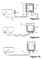
- Figure 5 shows a third embodiment of the present invention in which the outer container 32 is lined with insulation 48. Since the reagent is held within the flexible member the insulation does not need to be reagent proof and may therefore be a cheap and efficient foam or fibre. As well as reducing the likelihood of freezing and reducing the time to thaw, the insulation may also advantageously minimize any noise radiated if lumps of ice knock against the walls of the flexile member 30. The insulation may also provide space for ice within the inner container 30 to expand without applying additional stresses to the outer container 32.
- Figure 6 shows a fourth embodiment of the present invention in which a dosing unit 17 has been integrated within the container.
- Figure 7 shows a fifth embodiment of the present invention in which a fluid 50 may be introduced between the two containers via an inlet 51 (air gap fluid inlet) in the outer container.
- This fluid could for example be pressurized air from a turbocharger or from a braking system, pressurized fuel from a low pressure circuit of a fuel injection system, or pressurized coolant from a vehicle cooling system.
- a special air pump may also be provided to pressurize this space. This has the advantage that only a dosing valve 52 needs to be exposed to the reagent rather than the pump.
- Figure 8 shows a sixth embodiment of the present invention which is a variation of the fifth embodiment of the present invention.
- a through flow of fluid 50 through the space has been arranged.
- heat from the fluid e.g. engine coolant
- a valve or thermostat 54 connected to the reservoir tank 28 by pipe 56, may be used to control this flow to only heat the reagent when required.
- the flow pipe 56 may be run adjacent to around, or through the reagent pipe 23 in order to thaw that pipe 23 as well.
- Fluid 50 enters the space between the inner and outer containers via inlet 51 and exits via outlet 53 (air gap fluid outlet).
- Figure 9 shows a seventh embodiment of the present invention.
- any or all of the functions mentioned for Figure 5 may be introduced into a base plate 58 to which the container 28 is mounted.
- This has the advantage that the most expensive and fragile parts remain attached to the vehicle.
- a radio frequency identification tag 60 may be provided in or on the reservoir tank 28. This may be a simple fusible tag as used for security at retail outlets or may contain a chip to register data such as the quantity of reagent remaining and/or the reagent type or age.
- a fusible tag this could be fused by the ECU when the container is fitted so that the container cannot be re-used unless filled by an authorized filler and then fitted with a new tag.
- the tag may also be directly electrically connected or read, written to or deleted by the ECU using optical, thermal, magnetic or ultrasonic means.
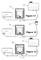
- Figure 10 shows an eighth embodiment of the present invention which is similar to the embodiment shown in Figure 9 . As shown in Figure 10 , however, the base plate 58 may also have an integrated dosing unit 17.
- Figure 11 shows a ninth embodiment of the present invention.
- the system comprises a reservoir tank 28 and a further tank 62 which is in fluid communication with the tank 28 via inlet 61.
- the reservoir tank may be a reservoir tank according to any of embodiments one to eight.
- the arrangement of Figure 11 may be used when it is desired to allow filling with reagent from any source and/or when there is not a suitable space in the vehicle to fit a removable container.
- quality, temperature and/or level sensors may be located in the further tank and/or the container or base plate.
- a further advantage of this system is that the reservoir tank 28 can be small and quickly unfrozen as it only needs to contain a small quantity of reagent.
- the further tank 62 can be allowed to freeze, as it only needs to unfreeze at sufficient intervals to re-fill the reservoir tank.
- Figure 12 shows a tenth embodiment of the present invention which is similar to that of Figure 11 . If there is space to fit a large enough reservoir tank, but it cannot be easily removed, the arrangement of Figure 12 may be used, where a sealed filler cap 64 or filling valve is located at a convenient point on the vehicle.
- Figure 13 shows an eleventh embodiment of the present invention in which a pressurized gas or vapour 66 is sealed between the inner 30 and outer containers 32.
- a pressurizing pump 68 is used to pump fluid into the reservoir tank and a dosing valve 52 is used to deliver it.
- This has the advantage that the pump can be operated at any time (e.g. when any noise would not be heard), and the store of pre-pressurized reagent can be used at any time.
- a simple filling valve could be used on the inlet and the reservoir tank pre-pressurized when it is filled.
- a pressure sensor may be used to detect the reagent level.
- the regent level within the container may also be detected by bouncing ultrasonic pulses from the bottom to the top of the inner container and measuring the time for them to return. By analysis of the spectrum of the return pulses, it may also be possible to detect the density (and therefore strength) of the reducing agent.
- the reagent level and quality may also be measured by an electrical resistance or capacitance through the fluid in the inner container from the top to the bottom.
Landscapes
- Chemical & Material Sciences (AREA)
- Engineering & Computer Science (AREA)
- Chemical Kinetics & Catalysis (AREA)
- Health & Medical Sciences (AREA)
- Toxicology (AREA)
- Combustion & Propulsion (AREA)
- Mechanical Engineering (AREA)
- General Engineering & Computer Science (AREA)
- Exhaust Gas After Treatment (AREA)
- Exhaust Gas Treatment By Means Of Catalyst (AREA)
Priority Applications (3)
| Application Number | Priority Date | Filing Date | Title |
|---|---|---|---|
| EP07252744A EP2014886A1 (de) | 2007-07-09 | 2007-07-09 | Behälter für ein Flüssigkeitsdosierungssystem |
| US12/217,367 US20090013670A1 (en) | 2007-07-09 | 2008-07-03 | Reservoir for a fluid dosing system |
| JP2008179018A JP2009013988A (ja) | 2007-07-09 | 2008-07-09 | 流体投与システム用リザーバ |
Applications Claiming Priority (1)
| Application Number | Priority Date | Filing Date | Title |
|---|---|---|---|
| EP07252744A EP2014886A1 (de) | 2007-07-09 | 2007-07-09 | Behälter für ein Flüssigkeitsdosierungssystem |
Publications (1)
| Publication Number | Publication Date |
|---|---|
| EP2014886A1 true EP2014886A1 (de) | 2009-01-14 |
Family
ID=38779913
Family Applications (1)
| Application Number | Title | Priority Date | Filing Date |
|---|---|---|---|
| EP07252744A Withdrawn EP2014886A1 (de) | 2007-07-09 | 2007-07-09 | Behälter für ein Flüssigkeitsdosierungssystem |
Country Status (3)
| Country | Link |
|---|---|
| US (1) | US20090013670A1 (de) |
| EP (1) | EP2014886A1 (de) |
| JP (1) | JP2009013988A (de) |
Cited By (14)
| Publication number | Priority date | Publication date | Assignee | Title |
|---|---|---|---|---|
| WO2010112726A1 (fr) * | 2009-04-02 | 2010-10-07 | Peugeot Citroën Automobiles SA | Reservoir d'uree, ligne d'echappement et vehicule |
| FR2949503A1 (fr) * | 2009-08-27 | 2011-03-04 | Coutier Moulage Gen Ind | Reservoir souple pour produit additif |
| FR2949504A1 (fr) * | 2009-08-27 | 2011-03-04 | Coutier Moulage Gen Ind | Reservoir souple pour produit additif |
| FR2951775A1 (fr) * | 2009-10-23 | 2011-04-29 | Coutier Moulage Gen Ind | Dispositif d'injection d'un produit additif dans une ligne de traitement |
| EP2400125A1 (de) * | 2010-06-24 | 2011-12-28 | Robert Bosch GmbH | Flanschmodul für einen Vorratstank |
| WO2012107315A1 (en) * | 2011-02-10 | 2012-08-16 | Inergy Automotive Systems Research | Scr system for an internal combustion engine |
| EP2489845A1 (de) * | 2010-12-14 | 2012-08-22 | Hilite Germany GmbH | SCR-Abgasnachbehandlungseinrichtung |
| EP2639421A1 (de) * | 2012-03-13 | 2013-09-18 | Peugeot Citroën Automobiles Sa | Vorratsbehälter und Verfahren zur Erkennung eines Behältertausches |
| US8875491B2 (en) | 2007-01-25 | 2014-11-04 | Cummins Ltd. | Exhaust gas aftertreatment system and method |
| US8938949B2 (en) | 2009-08-03 | 2015-01-27 | Cummins Ltd. | SCR exhaust gas aftertreatment device |
| EP2829699A1 (de) * | 2013-07-24 | 2015-01-28 | Inergy Automotive Systems Research (Société Anonyme) | Motorabgaszusatzspeichersystem |
| US8959895B2 (en) | 2008-03-05 | 2015-02-24 | Cummins Ltd. | Exhaust-gas aftertreatment device |
| EP2846012A1 (de) * | 2013-09-10 | 2015-03-11 | Inergy Automotive Systems Research (Société Anonyme) | System zur Reinigung der Abgase eines Verbrennungsmotors |
| EP3145757B1 (de) * | 2014-05-21 | 2021-01-20 | Castrol Limited | Fluidsystem und -verfahren |
Families Citing this family (14)
| Publication number | Priority date | Publication date | Assignee | Title |
|---|---|---|---|---|
| DE102008023437B4 (de) * | 2008-05-14 | 2012-12-06 | Pierburg Gmbh | Kraftfahrzeug-SCR-Feststoff-Speicheranordnung |
| DE102008044708A1 (de) * | 2008-08-28 | 2010-03-04 | Emitec Gesellschaft Für Emissionstechnologie Mbh | SCR-System mit Kompensationselement |
| US20110138791A1 (en) * | 2009-12-15 | 2011-06-16 | Delphi Technologies, Inc. | Liquid Reductant Dosing Module with Heating Device |
| JP2011197411A (ja) * | 2010-03-19 | 2011-10-06 | Olympus Corp | 撮像モジュール |
| JP5484152B2 (ja) * | 2010-03-26 | 2014-05-07 | ダンロップスポーツ株式会社 | ゴルフボール |
| US8881507B2 (en) * | 2011-08-22 | 2014-11-11 | Mi Yan | Air driven reductant delivery system |
| EP2565412A1 (de) * | 2011-08-29 | 2013-03-06 | Inergy Automotive Systems Research (Société Anonyme) | Zufuhrsystem für eine Flüssigkeit |
| DE102011118929A1 (de) * | 2011-11-21 | 2013-05-23 | Kautex Textron Gmbh & Co. Kg | Nebenflüssigkeitsbehälter für ein Kfz |
| DE102012007691A1 (de) * | 2012-04-19 | 2013-10-24 | Emitec Gesellschaft Für Emissionstechnologie Mbh | Vorrichtung zum Bereitstellen eines flüssigen Additivs |
| US20140318654A1 (en) * | 2013-04-27 | 2014-10-30 | Royce Rasmussen | Supply of fluid for a recreational vehicle |
| US11028752B2 (en) * | 2018-02-12 | 2021-06-08 | Cummins Emission Solutions Inc. | Reductant insertion assembly comprising a bladder |
| JP6958464B2 (ja) * | 2018-04-11 | 2021-11-02 | トヨタ自動車株式会社 | 内燃機関の排気浄化装置 |
| US11319852B2 (en) * | 2019-08-27 | 2022-05-03 | Caterpillar Inc. | Systems and methods for fluid level and quality measurement for reductant storage systems |
| US11655750B2 (en) * | 2020-09-08 | 2023-05-23 | Norco Industries, Inc. | Vehicle engine flushing machine with heating and reverse flow |
Citations (6)
| Publication number | Priority date | Publication date | Assignee | Title |
|---|---|---|---|---|
| DE19743337C1 (de) * | 1997-09-30 | 1999-01-07 | Siemens Ag | NOx-Reduktionssystem mit einer Einrichtung zur Reduktionsmitteldosierung |
| JP2000027627A (ja) * | 1998-07-13 | 2000-01-25 | Hino Motors Ltd | 排気ガス浄化触媒用還元剤保温装置及びそれを組込んだ排気ガス浄化装置 |
| EP1199097A1 (de) * | 2000-10-19 | 2002-04-24 | Hydraulik-Ring GmbH | Einrichtung zur Abgasnachbehandlung von Dieselmotoren |
| US20050211754A1 (en) * | 2004-03-26 | 2005-09-29 | Fred Fulcher | Dispenser for hot and cold beverages and food |
| JP2006144562A (ja) * | 2004-11-16 | 2006-06-08 | Hino Motors Ltd | 尿素水貯蔵装置 |
| WO2007017080A1 (de) * | 2005-08-06 | 2007-02-15 | Eichenauer Heizelemente Gmbh & Co. Kg | Heizsystem |
Family Cites Families (9)
| Publication number | Priority date | Publication date | Assignee | Title |
|---|---|---|---|---|
| JPS5440691B2 (de) * | 1972-05-31 | 1979-12-05 | ||
| WO1996008639A1 (de) * | 1994-09-13 | 1996-03-21 | Siemens Aktiengesellschaft | Verfahren und einrichtung zum einbringen von flüssigkeit in eine abgasreinigungsvorrichtung |
| US6063350A (en) * | 1997-04-02 | 2000-05-16 | Clean Diesel Technologies, Inc. | Reducing nox emissions from an engine by temperature-controlled urea injection for selective catalytic reduction |
| DE19807935C1 (de) * | 1998-02-25 | 1999-08-26 | Siemens Ag | Vorrichtung zur Reduzierung des NO¶x¶-Gehaltes im Abgas einer Brennkraftmaschine |
| JP3521798B2 (ja) * | 1999-04-26 | 2004-04-19 | トヨタ自動車株式会社 | 内燃機関の排気浄化装置 |
| EP1236499B1 (de) * | 2001-03-02 | 2004-05-19 | Haldor Topsoe A/S | SCR Verfahren und Vorrichtung zur Reduktion von NOx-Emissionen |
| JP3751962B2 (ja) * | 2003-09-05 | 2006-03-08 | 日産ディーゼル工業株式会社 | エンジンの排気浄化装置 |
| JP2005188448A (ja) * | 2003-12-26 | 2005-07-14 | Hitachi Ltd | 内燃機関の燃料供給系制御装置 |
| DE102004063071B4 (de) * | 2004-12-28 | 2021-10-14 | Robert Bosch Gmbh | Fahrzeug mit einer Versorgungseinheit |
-
2007
- 2007-07-09 EP EP07252744A patent/EP2014886A1/de not_active Withdrawn
-
2008
- 2008-07-03 US US12/217,367 patent/US20090013670A1/en not_active Abandoned
- 2008-07-09 JP JP2008179018A patent/JP2009013988A/ja not_active Ceased
Patent Citations (6)
| Publication number | Priority date | Publication date | Assignee | Title |
|---|---|---|---|---|
| DE19743337C1 (de) * | 1997-09-30 | 1999-01-07 | Siemens Ag | NOx-Reduktionssystem mit einer Einrichtung zur Reduktionsmitteldosierung |
| JP2000027627A (ja) * | 1998-07-13 | 2000-01-25 | Hino Motors Ltd | 排気ガス浄化触媒用還元剤保温装置及びそれを組込んだ排気ガス浄化装置 |
| EP1199097A1 (de) * | 2000-10-19 | 2002-04-24 | Hydraulik-Ring GmbH | Einrichtung zur Abgasnachbehandlung von Dieselmotoren |
| US20050211754A1 (en) * | 2004-03-26 | 2005-09-29 | Fred Fulcher | Dispenser for hot and cold beverages and food |
| JP2006144562A (ja) * | 2004-11-16 | 2006-06-08 | Hino Motors Ltd | 尿素水貯蔵装置 |
| WO2007017080A1 (de) * | 2005-08-06 | 2007-02-15 | Eichenauer Heizelemente Gmbh & Co. Kg | Heizsystem |
Cited By (22)
| Publication number | Priority date | Publication date | Assignee | Title |
|---|---|---|---|---|
| US8875491B2 (en) | 2007-01-25 | 2014-11-04 | Cummins Ltd. | Exhaust gas aftertreatment system and method |
| US8959895B2 (en) | 2008-03-05 | 2015-02-24 | Cummins Ltd. | Exhaust-gas aftertreatment device |
| FR2943999A1 (fr) * | 2009-04-02 | 2010-10-08 | Peugeot Citroen Automobiles Sa | Reservoir d'uree, ligne d'echappement et vehicule |
| WO2010112726A1 (fr) * | 2009-04-02 | 2010-10-07 | Peugeot Citroën Automobiles SA | Reservoir d'uree, ligne d'echappement et vehicule |
| US8938949B2 (en) | 2009-08-03 | 2015-01-27 | Cummins Ltd. | SCR exhaust gas aftertreatment device |
| FR2949503A1 (fr) * | 2009-08-27 | 2011-03-04 | Coutier Moulage Gen Ind | Reservoir souple pour produit additif |
| FR2949504A1 (fr) * | 2009-08-27 | 2011-03-04 | Coutier Moulage Gen Ind | Reservoir souple pour produit additif |
| EP2299077A1 (de) * | 2009-08-27 | 2011-03-23 | Mgi Coutier | Flexibler Tank für Additiv |
| WO2011048292A3 (fr) * | 2009-10-23 | 2013-07-18 | Mgi Coutier | Dispositif d'injection d'un produit additif liquide dans une ligne de traitement |
| FR2951775A1 (fr) * | 2009-10-23 | 2011-04-29 | Coutier Moulage Gen Ind | Dispositif d'injection d'un produit additif dans une ligne de traitement |
| EP2400125A1 (de) * | 2010-06-24 | 2011-12-28 | Robert Bosch GmbH | Flanschmodul für einen Vorratstank |
| EP2489845A1 (de) * | 2010-12-14 | 2012-08-22 | Hilite Germany GmbH | SCR-Abgasnachbehandlungseinrichtung |
| US8875502B2 (en) | 2010-12-14 | 2014-11-04 | Cummins Ltd. | SCR exhaust gas aftertreatment device |
| WO2012107315A1 (en) * | 2011-02-10 | 2012-08-16 | Inergy Automotive Systems Research | Scr system for an internal combustion engine |
| EP2639421A1 (de) * | 2012-03-13 | 2013-09-18 | Peugeot Citroën Automobiles Sa | Vorratsbehälter und Verfahren zur Erkennung eines Behältertausches |
| FR2988134A1 (fr) * | 2012-03-13 | 2013-09-20 | Peugeot Citroen Automobiles Sa | Reservoir de stockage et procede de detection de changement de reservoir |
| EP2829699A1 (de) * | 2013-07-24 | 2015-01-28 | Inergy Automotive Systems Research (Société Anonyme) | Motorabgaszusatzspeichersystem |
| WO2015011168A1 (en) * | 2013-07-24 | 2015-01-29 | Inergy Automotive Systems Research (Société Anonyme) | Engine exhaust gas additive storage system |
| CN105705740A (zh) * | 2013-07-24 | 2016-06-22 | 全耐塑料高级创新研究公司 | 发动机排放气体添加剂存储系统 |
| CN105705740B (zh) * | 2013-07-24 | 2018-10-26 | 全耐塑料高级创新研究公司 | 发动机排放气体添加剂存储系统 |
| EP2846012A1 (de) * | 2013-09-10 | 2015-03-11 | Inergy Automotive Systems Research (Société Anonyme) | System zur Reinigung der Abgase eines Verbrennungsmotors |
| EP3145757B1 (de) * | 2014-05-21 | 2021-01-20 | Castrol Limited | Fluidsystem und -verfahren |
Also Published As
| Publication number | Publication date |
|---|---|
| JP2009013988A (ja) | 2009-01-22 |
| US20090013670A1 (en) | 2009-01-15 |
Similar Documents
| Publication | Publication Date | Title |
|---|---|---|
| EP2014886A1 (de) | Behälter für ein Flüssigkeitsdosierungssystem | |
| US11639289B2 (en) | Fluid dispensing unit having a circulation system and a method for circulating a fluid in a fluid dispensing unit | |
| CA2374253C (en) | Process for the reduction of scr nox emissions and apparatus therefore | |
| US8857160B2 (en) | Reservoir for accommodating an aqueous solution | |
| JP5629748B2 (ja) | エンジン排気ガス添加剤貯蔵システム | |
| US6519935B2 (en) | Device and method for exhaust-gas aftertreatment in an internal-combustion engine | |
| US6502390B2 (en) | Method and system for feeding a reducing agent into a catalyst device | |
| US20070163245A1 (en) | Reagent refill and supply system for an SCR exhaust aftertreatment system | |
| EP1925804A1 (de) | Abgasreiniger für motor | |
| JP2009530536A (ja) | 自動車の排気ガスにおける有害物質低減のための方法および調量システム | |
| US8402750B2 (en) | Reagent tank normalizing system | |
| US20140065022A1 (en) | Exhaust Gas After Treatment System | |
| CN103562703B (zh) | 用于检测流体品质的传感器 | |
| KR20160043135A (ko) | 엔진 배기 가스 첨가제의 저장 시스템 | |
| KR20150119317A (ko) | 요소 온도 합리성 진단 기구를 갖는 배기 가스 처리 시스템 | |
| US20140202593A1 (en) | Device for filling a tank of a motor vehicle | |
| CN102162390B (zh) | 一种多次定量精确喷射的选择性催化还原系统 | |
| CN108301905A (zh) | 氨气尿素双喷射系统及其控制方法 | |
| US20160222859A1 (en) | Method and system for detecting malfunctioning of fluid tank of machine | |
| US8491859B2 (en) | Device having an injector for a liquid reducing agent, configuration having the device and methods of using the device and the configuration | |
| US10107170B2 (en) | Method for validating signals generated by acoustic sensors | |
| US9523301B2 (en) | Reducing agent metering system with leak monitoring | |
| CN115217588A (zh) | 废气还原系统的具有干燥器件的部件 |
Legal Events
| Date | Code | Title | Description |
|---|---|---|---|
| PUAI | Public reference made under article 153(3) epc to a published international application that has entered the european phase |
Free format text: ORIGINAL CODE: 0009012 |
|
| AK | Designated contracting states |
Kind code of ref document: A1 Designated state(s): AT BE BG CH CY CZ DE DK EE ES FI FR GB GR HU IE IS IT LI LT LU LV MC MT NL PL PT RO SE SI SK TR |
|
| AX | Request for extension of the european patent |
Extension state: AL BA HR MK RS |
|
| 17P | Request for examination filed |
Effective date: 20090714 |
|
| AKX | Designation fees paid |
Designated state(s): AT BE BG CH CY CZ DE DK EE ES FI FR GB GR HU IE IS IT LI LT LU LV MC MT NL PL PT RO SE SI SK TR |
|
| RAP1 | Party data changed (applicant data changed or rights of an application transferred) |
Owner name: DELPHI TECHNOLOGIES HOLDING S.A.R.L. |
|
| 17Q | First examination report despatched |
Effective date: 20110503 |
|
| STAA | Information on the status of an ep patent application or granted ep patent |
Free format text: STATUS: THE APPLICATION IS DEEMED TO BE WITHDRAWN |
|
| 18D | Application deemed to be withdrawn |
Effective date: 20110914 |