EP2012095A2 - Durchflusssensor - Google Patents
Durchflusssensor Download PDFInfo
- Publication number
- EP2012095A2 EP2012095A2 EP20080252305 EP08252305A EP2012095A2 EP 2012095 A2 EP2012095 A2 EP 2012095A2 EP 20080252305 EP20080252305 EP 20080252305 EP 08252305 A EP08252305 A EP 08252305A EP 2012095 A2 EP2012095 A2 EP 2012095A2
- Authority
- EP
- European Patent Office
- Prior art keywords
- flow
- flow path
- flow rate
- fluid
- paths
- Prior art date
- Legal status (The legal status is an assumption and is not a legal conclusion. Google has not performed a legal analysis and makes no representation as to the accuracy of the status listed.)
- Withdrawn
Links
Images




Classifications
-
- G—PHYSICS
- G01—MEASURING; TESTING
- G01F—MEASURING VOLUME, VOLUME FLOW, MASS FLOW OR LIQUID LEVEL; METERING BY VOLUME
- G01F1/00—Measuring the volume flow or mass flow of fluid or fluent solid material wherein the fluid passes through a meter in a continuous flow
- G01F1/68—Measuring the volume flow or mass flow of fluid or fluent solid material wherein the fluid passes through a meter in a continuous flow by using thermal effects
- G01F1/684—Structural arrangements; Mounting of elements, e.g. in relation to fluid flow
- G01F1/6842—Structural arrangements; Mounting of elements, e.g. in relation to fluid flow with means for influencing the fluid flow
-
- G—PHYSICS
- G01—MEASURING; TESTING
- G01F—MEASURING VOLUME, VOLUME FLOW, MASS FLOW OR LIQUID LEVEL; METERING BY VOLUME
- G01F1/00—Measuring the volume flow or mass flow of fluid or fluent solid material wherein the fluid passes through a meter in a continuous flow
-
- G—PHYSICS
- G01—MEASURING; TESTING
- G01F—MEASURING VOLUME, VOLUME FLOW, MASS FLOW OR LIQUID LEVEL; METERING BY VOLUME
- G01F15/00—Details of, or accessories for, apparatus of groups G01F1/00 - G01F13/00 insofar as such details or appliances are not adapted to particular types of such apparatus
-
- G—PHYSICS
- G01—MEASURING; TESTING
- G01F—MEASURING VOLUME, VOLUME FLOW, MASS FLOW OR LIQUID LEVEL; METERING BY VOLUME
- G01F15/00—Details of, or accessories for, apparatus of groups G01F1/00 - G01F13/00 insofar as such details or appliances are not adapted to particular types of such apparatus
- G01F15/12—Cleaning arrangements; Filters
-
- G—PHYSICS
- G01—MEASURING; TESTING
- G01F—MEASURING VOLUME, VOLUME FLOW, MASS FLOW OR LIQUID LEVEL; METERING BY VOLUME
- G01F15/00—Details of, or accessories for, apparatus of groups G01F1/00 - G01F13/00 insofar as such details or appliances are not adapted to particular types of such apparatus
- G01F15/14—Casings, e.g. of special material
Definitions
- the present invention relates to a flow meter wherein the flow path structure is improved so as to increase the detection sensitivity of a flow rate sensor to minute flow rates, and the detection sensitivity to large flow rates is reduced so as to expand the dynamic range of measurement with the aforementioned flow rate sensor.
- detection sensitivity to minute flow rates As the detection sensitivity to minute flow rates is increased as described above, detection sensitivity to large flow rates will also increase, causing a problem in that during the throughflow of a large flow rate, the output of the flow rate sensor will saturate, making measurement impossible. For this reason, in a gas meter or the like having a maximum measurable flow rate of approximately 30,000 L/h, for example, minute leakage flow rates of approximately 5 L/h were difficult to detect with good accuracy.
- the present invention may provide a flow meter capable of detecting easily and with good accuracy flows ranging from minute flow rates such as gas leaks to large flow rates during the state of normal gas usage.
- the flow meter of the present invention comprises a flow path structure that has been improved so that flow rates ranging from a minute flow rate of approximately 5 [L/h] to a large flow rate of approximately 30,000 [L/h], for example, can be measured without causing the output of the flow rate sensor to saturate, and is basically characterized by
- the first and second flow paths are formed by spatially compartmentalizing the flow path cross-section of the main flow path along the direction of fluid flow through the main flow path, and are configured such that, for example, at least one of the first and second flow paths is caused to passively change its flow path resistance to the fluid in accordance with the flow rate of the fluid through the main flow path, and the flow diversion ratio among the first and second flow paths is caused to change.
- the first and second flow paths are formed by compartmentalizing the flow path cross-section of the main flow path with partitions provided along the direction of fluid flow through the main flow path, for example, and in particular, the first flow path is formed preferably as a flow path space having a smaller flow path cross-section than that of the second flow path.
- the first flow path after having secured an inlet zone of a predetermined length for the fluid flow, is provided downstream from the inlet zone with a narrow area that constricts the cross-sectional area of that flow path, and the flow rate sensor is incorporated preferably into this narrow area.
- an inlet zone of a predetermined length for the fluid flow is secured, a narrow area that constricts the flow path cross-sectional area is provided downstream from that inlet zone, and preferably the flow rate sensor is incorporated into this narrow area.
- the first flow path comprises a laminar flow region formed as a region smaller than the flow path cross-section of the main flow path, for example, and formed downstream of a mesh-free area provided on a portion of a mesh element provided so as to cover the entire flow path cross-section of the main flow path.
- the second flow path is formed by equivalently compartmentalizing the space between the laminar flow region and the flow path cross-section of the main flow path, and is realized as a region outside the laminar flow region downstream from the mesh element.
- a plurality of the mesh elements provided with mesh-free areas may also be provided such that the locations of the mesh-free areas thereof are aligned in the throughflow direction of the fluid.
- the first and second flow paths can be configured such that the flow diversion ratio between the first and second flow paths varies according to the second flow path resistance, which changes according to the degree of opening of the paddle mechanism.
- the second flow path may preferably be provided with grid-shaped partition plates that compartmentalize the second flow path into a plurality of parallel minute flow paths along the fluid flow.
- the grid-shaped partition plates are realized as grid elements of a predetermined length, a plurality of the grid elements are arranged in series in the fluid throughflow direction of the second flow path, and a mesh element is interposed between each of these grid elements.
- the provision of a second flow rate sensor in the second flow path is useful in compensating for the degradation in measurement accuracy of large flow rates when measuring the flow rate in conjunction with this second flow rate sensor.
- the ratio of flow diverted among a first flow path and a second flow path provided in parallel changes passively according to the flow rate of fluid flowing through a main flow path. Accordingly, in the case when, for example, the fluid flowing through the main flow path is small, the flow diversion ratio for the first flow path has a high value, and as the flow of fluid through the main flow path increases, the flow diversion ratio for the first flow path decreases, and the provision of a flow rate sensor in the first flow path enables that flow rate sensor to detect flows ranging from minute flow rates to large flow rates.
- the flow velocity of the minute flow guided to the first flow path can be sped-up in the aforementioned narrow area.
- the sensitivity of detection by the flow rate sensor can be increased substantially, and minute flow rates can be detected easily.
- the abovementioned narrow area acts as a flow path resistance for large flow rates and is therefore extremely effective for passively changing the flow diversion ratio among the first and second flow paths.
- the abovementioned mesh element, the grid element, and the paddle mechanism act as flow path resistances for minute flow rates and are therefore extremely effective for passively changing the flow diversion ratio among the first and second flow paths.
- fluid is used throughout the specification and is defined as a liquid, a gas, or both depending on the context. Further, the fluid can be Newtonian or non-Newtonian.
- This flow meter is configured as a suitable gas meter using a thermal type flow rate sensor that detects the mass flow rate of a gas flow, for example.
- the aforementioned thermal type flow rate sensor is comprised, for example, of a pair of thermosensitive resistive elements provided in the direction of fluid flow between heat-generating resistive elements and mounted on a thin diaphragm formed on a silicon or glass substrate, and is configured so as to detect the flow rate (flow velocity) of the aforementioned fluid from changes in the distribution of temperature near the sensor surface due to the flow of fluid along the sensor surface.
- FIG. 1 shows the basic configuration of the flow meter of the present invention.
- a fluid such as gas
- the aforementioned fluid is diverted and flows through the first and second flow paths 2, 3 which are provided in a parallel arrangement.
- the aforementioned first and second flow paths 2, 3 comprise the equivalent of a resistive circuit such as shown in FIG. 2 wherein a flow path resistance R1 of the first flow path 2 and a flow path resistance R2 of the second flow path 3 are caused to change passively according to a fluid flow rate (flow velocity) V through the main flow path 1, and as a result, cause a change in the flow diversion ratio among the first and second flow paths 2, 3.
- the flow diversion ratio among the first and second flow paths changes non-mechanically based on the flow rate of the fluid.
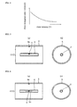
- the first and second flow paths 2, 3 comprise a flow path structure wherein the flow path resistances R1, R2 change passively as shown in FIG. 3 according to the fluid flow rate (flow velocity) V through the main flow path 1, for example, and the fluid is diverted into flow rates 11, 12 that flow through the respective flow paths according to the aforementioned flow path resistances R1 and R2, and the flow diversion ratio [I1/(I1 + 12)] thereof changes according to the fluid flow rate (flow velocity) V as shown in FIG. 4 .
- either one of the first or second flow paths 2, 3 may passively change their flow path resistance R1 or flow path resistance R2 according the fluid flow rate (flow velocity) V through the main flow path 1.
- the ratio of flow diversion [I1/(I1 + 12)] among the first and second flow paths will change according to the change in either flow path resistance R1 or R2.
- a thermal type flow rate sensor 4 is incorporated into at least one of the above-described first and second flow paths 2, 3 of a flow meter having this type of flow path structure.
- FIGS.5 (a), (b) The aforementioned first and second flow paths 2, 3 are formed as shown in FIGS.5 (a), (b) , for example, wherein inside a pipe (large diameter pipe) 5 forming the main flow path 1, a small diameter pipe 6 acting as a partition is provided in the direction of flow thereof so as to compartmentalize the interior space of the aforementioned pipe 5 in the cross-sectional direction of the flow path.
- FIG. 5 (a) shows a longitudinal cross-section of the flow path structure
- FIG. 5 (b) shows the transverse cross-sectional structure of that flow path.
- the flow path resistances R1, R2 of the first and second flow paths 2, 3 change differently according to the fluid flow rate (flow velocity) V through the pipe 5.
- the flow path resistance R1 of the first flow path 2 having a minute flow path cross-sectional area and being formed as the space inside the small diameter pipe 6 is only slightly larger than the flow path resistance R2 of the second flow path 3 having a large flow path cross-sectional area and being formed as the space outside the small diameter pipe 6.
- the provision of a flow rate sensor 4 in the first flow path 2 enables the aforementioned minute flow to be detected reliably by that flow rate sensor 4.
- the flow diversion ratio among the first and second flow paths 2, 3 changes according to the increase in flow path resistance R1 of the first flow path 2, and the increase in flow rate of the fluid through the first flow path 2 is constrained so that the flow can be detected without causing the flow rate sensor 4 to saturate.
- the provision of a narrow area (nozzle) 6a that constricts the pipe diameter (flow path cross-sectional area) enables an even greater change in the flow path resistance R1 of the first flow path 2 as the fluid flow rate (flow velocity) V through the pipe 5 increases.
- a narrow area (nozzle) 6a exists at an intermediate location in the small diameter pipe 6, the fluid constricted in the small diameter pipe 6 is compressed while flowing through the interior of the small diameter pipe 6 and flows through the narrow area 6a with an increased flow velocity.
- the flow diversion ratio among the first and second flow paths 2, 3 is caused to change according to the flow, and because the flow through the first flow path 2 can be constrained when the flow is large, flows ranging from small flow rates to large flow rates can be detected reliably, without causing the flow rate sensor 4 to saturate.
- the flow rate sensor 4 in the above-described narrow area 6a, the velocity of fluid flow through the first flow path 2 at the narrow area 6a can be increased so that even minute flow rates can be detected with high sensitively.
- each flow rate sensor 4 and the aforementioned second flow rate sensor 4a are provided in the same circumferential direction on the flow path peripheral surface. Consequently, in the prior art, a flow path length necessary for each flow rate region was required along the longitudinal direction for both the large flow rate region and a small flow rate region, but with the present invention, when providing different flow rate regions, each flow rate sensor is provided in the same circumferential direction on the flow path peripheral surface so that only a single flow path length is required in the flow rate regions. Thus, since the flow path length does not become elongated as in the prior art, this configuration enables miniaturization of the flow meter.
- FIGS. 7 (a), (b) for example, the provision of a mesh element 7 in the interior of the pipe 5 that forms the main flow path 1 so as to cover the flow path cross-sectional areas of the aforementioned first and second flow paths 2, 3 enables the space at the downstream side of the mesh element 7 to be compartmentalized in the flow path cross-sectional direction of the aforementioned pipe 5.
- FIG. 7(a) shows the longitudinal cross-section of the flow path structure
- FIG. 7 (b) shows the transverse cross-sectional structure of that flow path.
- a mesh-free area (notch) 7a In a portion of the aforementioned mesh element 7 is formed a mesh-free area (notch) 7a, and this mesh-free area 7a is positioned on a portion of the flow path cross-section surface of the aforementioned pipe 5, and is provided perpendicularly to the direction of fluid flow in the aforementioned pipe 5.
- the aforementioned mesh-free area 7a acts as a region in which the flow path resistance R1 is zero [0], and the mesh element 7 itself functions as a passive body that changes the flow path resistance R2 thereof according to the flow rate (flow velocity) V of fluid flowing through the pipe 5.
- the fluid flows formed in regions downstream from the mesh element 7 are formed as different sites by equivalently compartmentalizing the interior of the pipe 5 into the aforementioned first and second flow paths 2, 3.
- the first flow path 2 passes through the mesh-free area 7a and is realized as a laminar flow region formed downstream of the mesh-free area 7a.
- the second flow path 3 is realized as the region outside the aforementioned laminar flow region downstream of the aforementioned mesh element 7, or in other words, as the throughflow region of fluid that has passed through the mesh element 7.
- the fluid flowing through pipe 5 receives different flow path resistances according to whether that fluid passes through the mesh-free area 7a or passes through the mesh element 7.
- a minute fluid flow rate (flow velocity) V through the pipe 5 since there is a large flow path resistance (pressure drop) at the mesh element 7, nearly all of the aforementioned fluid flows through the mesh-free area 7a which has no flow path resistance. Accordingly, there is an increase in the flow rate through the region formed by the first flow path 2 downstream of the mesh-free area 7a, while the flow rate through the region formed by the second flow path 3 downstream of the mesh element 7 becomes essentially zero.
- the aforementioned flow rate sensor 4 since in the case of a minute fluid flow rate (flow velocity) V through the pipe 5 nearly all of that minute flow will be in the first flow path 2 (mesh-free area 7a), the aforementioned flow rate sensor 4 will be able to detect reliably that minute flow rate. Moreover, in the case where the fluid flow rate (flow velocity) V through the pipe 5 has increased, some of the aforementioned fluid will flow through the mesh element 7 and into the second flow path 3, and by that portion, the flow rate through the aforementioned first flow path 2 (mesh-free area 7a) is constrained.
- the flow divergence ratio among the first and second flow paths 2, 3 changes, and because the increase in fluid flow rate through the first flow path 2 is constrained, as in the above-described embodiment, the flow rate can be detected without causing the aforementioned flow rate sensor 4 to saturate.
- FIGS. 8 (a), (b) show the above-described first and second flow paths 2, 3 as shown in FIGS. 8 (a), (b) for example.
- FIG. 8 (a) shows the longitudinal cross-section of the flow path structure
- FIG. 8 (b) shows the transverse cross-sectional structure of that flow path.
- This flow path structure is configured in the interior of the pipe 5 that comprises the main flow path 1 by providing, along the fluid flow direction thereof, a plate-shaped partition 8 to compartmentalize the interior space of the main flow path 1 into the first and second flow paths 2, 3, and also by providing a paddle mechanism 9 by partitioning the second flow path 3 in the fluid flow direction thereof.
- This paddle mechanism 9 is equipped, for example, with a valve element 9a supported so as to be freely tilting via a hinge and provided so as to obstruct the second flow path 3, and upon receiving pressure from fluid flowing through the second flow path 3, tilts to form a gap in the second flow path 3, thus comprising a flow path resistor that functions so as to allow fluid to flow through this gap.
- this paddle mechanism 9 causes the size (degree of opening) of the gap formed by the aforementioned valve element 9a to change according to the fluid flow rate (flow velocity) V through the second flow path 3, and exhibits the function of a variable resistive element that passively changes its flow path resistance.
- a flow meter having a flow path structure equipped with this type of paddle mechanism 9, in the case where the fluid flow rate through the main flow path 1 minute, the paddle mechanism 9 provided in the second flow path 3 obstructs the second flow path 3 and therefore the aforementioned fluid with the minute flow rate flows exclusively through the first flow path 2. Then, in accordance with an increase in the fluid flow rate through the main flow path 1, upon receiving the fluid pressure thereof, the aforementioned valve element 9a of the paddle mechanism 9 opens and the flow path resistance thereof decreases so that the aforementioned fluid diverges and flows through the first and second flow paths 2,3.
- the provision of the flow rate sensor 4 in the first flow path 2 enables minute flow rates to be detected reliably since nearly all the fluid flows through the first flow path 2 when the flow rate is minute. Moreover, if the flow rate is increased, the valve element 9a of the paddle mechanism 9 opens as the flow rate is increased, and consequently, the flow diverges among the first and second flow paths so that the increase in fluid flow rate through the first flow path 2 is constrained. As a result, the flow rate can be detected while constraining saturation of the flow rate sensor 4, thus enabling the continuous detection of flows ranging from the above-described minute flow rate to a large flow rate.
- the flow rate through the first flow path 2 is constrained as described above, and by that portion, the accuracy of flow rate detection by the flow rate sensor 4 decreases. Therefore, compensation for the deterioration in large flow detection accuracy by the flow rate sensor 4 provided in the first flow path 2 can be achieved by providing a second flow rate sensor 4a, capable of detecting large flow rates with high accuracy, in the second flow path 3.
- a minute flow rate (flow velocity) V there is hardly any fluid flow to the second flow path 3 so that detection of the aforementioned minute flow rate with the second flow rate sensor 4a is nearly impossible. Accordingly, the detection of minute flow rates is relegated to the flow rate sensor 4 provided in the first flow path 2.
- the flow meter of the present invention is configured with a flow rate sensor 4 incorporated into at least one of the first and second flow paths 2, 3 which have a flow diversion ratio that changes passively when a minute flow rate or a large flow rate is flowing.
- incorporation of the flow rate sensor 4 in the flow path side where the diversion ratio increases during a minute flow rate and decreases during a large flow rate enables the continuous detection of flows ranging from minute flow rates to large flow rates by the flow rate sensor 4.
- the flow velocity (the apparent flow rate) thereof is increased substantially, and consequently, the minute flow rate can be detected reliably.
- the flow rate guided to the flow path (the first flow path 2) provided with the aforementioned flow rate sensor 4 an increase in flow velocity thereof is constrained, and consequently, the flow rate thereof is detected without saturating the aforementioned flow rate sensor 4.
- a single flow rate sensor 4 is continuously able to measure flow rates ranging from minute flow rates of approximately 5 [L/h] caused for example by gas leaks due to cracking or damage of the pipe 5 to large flow rates of approximately 30,000 [L/h] maximum during the state of normal gas usage, and this has many practical advantages.
- compensation for the deterioration in large flow detection accuracy by the above described flow rate sensor 4 can be achieved by providing in the other flow path (the second flow path 3 in the above-described example) a large flow rate-use second flow rate sensor 4a that is capable of detecting with high accuracy the flow rate during the state of normal gas usage, thus enabling the problem-free measurement of gas flow rates in practical applications.
- the aforementioned flow rate sensor 4 and the aforementioned flow rate sensor 4a are provided on the same circumferential direction on the flow path peripheral surface, and the large flow rate region and the small flow rate region are each formed with a predetermined flow path length. Accordingly, the flow path length required for forming the large flow rate measuring region and the small flow rate measuring region can be standardized. Consequently, a configuration that miniaturizes the size of the flow meter can be employed.
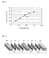
- FIG. 9 shows the flow path structure of a flow meter in a first embodiment of the present invention, in an exploded diagrammatic view in the fluid throughflow direction
- FIG. 10 shows a relevant part thereof in a diagrammatic view.
- This flow meter is configured with a grid element 12 as a main element that compartmentalizes the interior space of a pipe 11 having a rectangular shaped flow path cross-section into a plurality of minute flow paths in the flow path cross-sectional direction thereof.
- the abovementioned grid element 12 is configured with a plurality of plate-shaped partitions provided in parallel along the throughflow direction of the pipe 11 and assembled into a grid shape.
- the grid element 12 used in this embodiment includes, for example, a sensor grid element 12a that incorporates a flow rate sensor, as will be described later, first and second front grid elements 12b, 12c provided upstream from the sensor grid element 12a, and first and second rear grid elements 12d, 12d provided downstream from the sensor grid element 12a.
- these grid elements 12 (12a, 12b to 12e), for example, arrange a plurality (multiplicity) of minute flow paths 13 constituting approximately square shaped flow path cross-sectional shapes into a matrix, and form two minute flow paths 14 each constituting an approximately rectangular flow path cross-sectional shape and having a flow path cross-sectional area of approximately two times that of the aforementioned minute flow paths 13.
- These two minute flow paths 14 are formed, for example, at the sides of the grid element 12, by removing the plate-shaped partitions that compartmentalize two adjacent minute flow paths 13. Also, as shown in FIG.
- mesh elements (wire netting) 15 (15a, 15b, 15c, 15d) sandwiched between each of the grid elements 12 (12a, 12b to 12e) and superimposed in the fluid throughflow direction form a plurality of flow paths extending in the fluid throughflow direction. Furthermore, each of the aforementioned mesh elements (wire netting) 15 exclusively performs the role of straightening the flow of fluid through the above-described grid element 12.
- the abovementioned plurality (multiplicity) of minute flow paths 13 compartmentalized by the grid elements 12 (12a, 12b to 12e), if perceived collectively, can be considered as forming a flow path having a large flow path cross-sectional area.
- these minute flow paths 13, 14 exhibit different flow path resistances to the flow of fluid according to differences in their respective flow path cross-sectional areas. Accordingly, the minute flow paths 13 collectively can be considered as corresponding to the above-described second flow path 3, and the above-described two minute flow paths 14 can be considered as corresponding to the above-described first flow path 2.
- a nozzle 14a at one of the two minute flow paths 14 formed in the sensor grid element 12 is provided a nozzle 14a at an approximately intermediate location of the flow path, and the flow path cross-sectional area thereof is constricted.
- the minute flow path 14 provided with this nozzle 14a is used for minute flow rate detection (low velocities), and a low velocity-use flow rate sensor 16a is incorporated at the location where the abovementioned nozzle 14a constricts the flow path cross-sectional area.
- the other minute flow path 14 is used for large flow rate detection (high velocity-use) and a high velocity-use flow rate sensor 16b is incorporated at an approximately intermediate location thereof.
- the flow path cross-sectional area of each of the plurality of minute flow paths 13 that constitute the second flow path 3 is narrower than that of the minute flow paths 14 which incorporate flow rate sensors 16a, 16b, and due to their higher flow path resistance, in the case of a minute flow rate of fluid through the pipe 11, the fluid flows primarily to the minute flow paths 14 having smaller flow path resistance. Moreover, as the flow rate of fluid through the pipe 11 increases, the fluid overcomes the flow resistance of the abovementioned minute flow paths 13 and also flows into the minute flow paths 13.
- a nozzle 14a that constricts the flow path cross-sectional area thereof is provided as described above. Then, the aforementioned first and second front grid elements 12b, 12c provided upstream from the sensor grid element 12a providing with this nozzle 14a form an inlet zone for the fluid flowing into the minute flow path 14, and all the fluid that has flowed into this inlet zone is fed to the aforementioned nozzle 14a.
- the flow velocity of fluid having flowed into the minute flow path 14 increases due to the constriction of the flow path cross-sectional area by the aforementioned nozzle 14a, and the low velocity-use flow rate sensor 16a provided in the nozzle 14a of the aforementioned minute flow path 14 is able to detect minute flow rates with higher accuracy.
- the aforementioned low velocity-use flow rate sensor 16a is able to detect minute flow rates with higher accuracy than the high velocity-use flow rate sensor 16b provided in the other minute flow path 14 wherein the nozzle 14a is not formed.
- FIG. 11 shows experimental data that verifies the improvement in flow rate detection sensitivity in a flow path structure provided with the above-described grid element 12 and having a flow path compartmentalized into a plurality of minute flow paths 13, 14, and contrasts the flow rate sensor output in the case when the grid element 12 is not provided to the case where the grid element 12 is provided.
- This experimental data substantiates the improvement in sensitivity of flow rate detection by the flow rate sensors 16a, 16b in the case in which the grid element 12 is provided and the flow path is compartmentalized into minute flow paths 13, 14 compared to the case in which the flow path not provided with the grid element 12.
- the experimental data reveals that a longer length of the grid element 12 attains a greater improvement in detection sensitivity, and the reason for such is believed to be due to the increasing difference in change in flow path resistance among the aforementioned plurality of minute flow paths 13, 14 as the length (flow path length) of the grid element 12 increases.
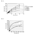
- FIG. 12 shows the change in flow rate sensor output for minute flow rates when the ratio of flow path cross-sectional areas (width of openings) of the plurality of minute flow paths 13, 14 formed by the grid element 12 is changed.
- the reference benchmark in FIG. 11 shows the case in which the opening widths (flow rate cross-sectional areas) of the minute flow paths 14 provided with the flow rate sensors 16 are equal to the opening widths (flow rate cross-sectional areas) of the other minute flow paths 13.
- the parameters indicated as 4 X and 8 X show the cases in which the opening widths (flow rate cross-sectional areas) of the minute flow paths 14 provided with the flow rate sensors 16 are set to 4 X and 8 X, respectively, of the opening widths (flow rate cross-sectional areas) of the minute flow paths 13.
- the experimental data shown in FIG. 12 substantiates the improvement in sensitivity of minute flow rate detection by the flow rate sensors 16 achieved by making the opening widths (flow rate cross-sectional areas) of the minute flow paths 14 provided with flow rate sensors 16 larger than the opening widths (flow rate cross-sectional areas) of the other minute flow paths 13 so that fluid in a minute flow rate region encounters difficulty in flowing into the aforementioned minute flow paths 13, and correspondingly, a larger flow rate will flow into the aforementioned minute flow paths 14 provided with the flow rate sensors 16.
- FIG. 13 verifies the effect of the presence of the above-described mesh element (wire netting) 15, and contrasts the change in sensor output over the range from a minute flow rate to a large flow rate. Furthermore, the case shown in which the mesh element (wire netting) 15 is not provided is the case in which the mesh element (wire netting) 15 has been omitted from the above-described flow path structure shown in FIG. 9 , or in other words, the case in which the flow path structure is configured with only the grid element 12.
- the provision of the mesh element (wire netting) 15 causes the straightening effect on the flows passing through each of the minute flow paths 13, 14 to become more prominent, enabling not only the detection of a stabilized flow rate, but also increased instantaneous flow rate measurement accuracy.
- the sensor output changes abruptly in response to changes in the flow rate in the minute flow rate region, and the detection sensitivity by the aforementioned flow rate sensors 16 in the minute flow rate region is high.
- the change in sensor output in response to the flow rate change broadens, indicating that the detection sensitivity by the aforementioned flow rate sensors 16 in the large flow rate region is gradually constrained lower.
- the constraining of detection sensitivity of the aforementioned flow rate sensors 16 in this large flow rate region is due to the pressure drop at the above-described nozzle 14a which increases proportionally to the square of the flow velocity (flow rate), and as a result thereof, the flow rate passing through the nozzle 14a (minute flow paths 14) is limited and the flow rate into the minute flow paths 13 increases. Also, with a flow meter that has adopted the abovementioned flow path structure, flows ranging from a minute flow rate to a large flow rate can be measured continuously, without causing the flow rate sensors 16 to saturate.
- FIG. 14 shows the change in sensor output in response to the flow rate at the low velocity-use flow rate sensor 16a and the high velocity-use flow rate sensor 16b provided in the above-described two minute flow paths 14 respectively.
- the rate of change of the output of the low velocity-use flow rate sensor 16a which is provided in the minute flow path 14 that is provided with the nozzle 14a and has a constricted flow path cross-sectional area, is constrained and a broad rate of change is exhibited. This phenomenon is caused by constraining the flow rate of fluid through the nozzle 14 which accompanies the pressure drop at the aforementioned nozzle 14a.
- FIG. 15 shows sensor output characteristics that change according to differences in the length (flow path length) of the grid element 12.
- This experimental data indicates that the longer the length of the grid element 12, the less effective the pressure drop at the nozzle 14a becomes, and the sensor output can be increased.
- This phenomenon is believed to be caused by the comparatively smaller change in the flow rate flowing into the minute flow paths 14 than the change in flow rate through the main flow path due to the greater compressibility of the fluid (gas) for longer flow path lengths of the minute flow paths 13, 14 compartmentalized by the grid element 12, and particularly for a longer inlet zone on the upstream side of the nozzle 14a.
- FIG. 16 shows an exploded diagrammatic view in the fluid throughflow direction of the flow path structure of a flow meter in a second embodiment of the present invention realized with this type of perspective
- FIG. 17 shows the cross-sectional structure of a relevant part thereof in a diagrammatic view.
- the grid elements 12 (12a, 12b to 12e) are similar to those of the above-described embodiment.
- this second embodiment differs from the above-described first embodiment in that a mesh element (wire netting) 17 formed with a rectangular shaped mesh-free area 17a is used as the mesh element sandwiched between each of the aforementioned grid elements 12 (12a, 12b to 12e), and particularly in that the location of the rectangular shaped mesh-free area 17a corresponds to the location at which the minute flow path 14 provided with the nozzle 14a is formed.
- a mesh element (wire netting) 17 formed with a rectangular shaped mesh-free area 17a is used as the mesh element sandwiched between each of the aforementioned grid elements 12 (12a, 12b to 12e)
- the location of the rectangular shaped mesh-free area 17a corresponds to the location at which the minute flow path 14 provided with the nozzle 14a is formed.
- FIG. 19 shows output characteristics of the low velocity-use flow rate sensor 16a and the high velocity-use flow rate sensor 16b in a flow meter configured as described above.
- a low velocity-use flow rate sensor 16a incorporated into the minute flow path 14 provided with the nozzle 14a and positioned at the location where the mesh-free area 17a is formed enables the detection sensitivity to be increased sufficiently in the minute flow rate region.
- the detection sensitivity in the large flow rate region decreases by the amount that the detection sensitivity has been increased sufficiently in the minute flow rate region.
- a high velocity-use flow rate sensor 16b incorporated into the minute flow path 14 provided with the mesh element 17 and not having a nozzle 14a
- the detection sensitivity across the entire measurement range, from the minute flow rate region to the large flow rate region can be made approximately uniform. Accordingly, by monitoring the output of each of the low velocity-use flow rate sensor 16a and the high velocity-use flow rate sensor 16b, the flow rate can be detected with good accuracy over the entire measurement range from minute flow rates of approximately 5 [L/h] caused by leaks to large flow rates of approximately 30,000 [L/h] maximum during the normal usage state, and this has many practical advantages. Moreover, by contrasting the output of each of these flow rate sensors 16a, 16b, the deterioration over time of the sensor characteristics can be monitored and other advantages provided.
- the present invention is not limited to the above-described embodiments.
- the ratio of the flow rate cross-sectional areas of the first and second flow paths 2, 3 may be determined according to measurement specifications or the like, or may be determined according the viscosity or the like that differs according to the type of fluid.
- grid elements are provided upstream and downstream from the sensor grid element 12a so that the flow path structure is symmetrical in the fluid throughflow direction.
- the fluid throughflow direction may invert, but in the case where the fluid throughflow direction is determined in a unified way, only on the upstream side of the sensor grid element 12a may grid elements 12b, 12c may be provided.
- the length of the flow path formed thusly with grid elements 12 may also be determined according to the specifications.
- the above-described mesh elements 7, 15, 17 are not only wire netting and may also be elements such as a honeycomb structure or perforated metal. Furthermore, the above-described grid elements 12, instead of forming a rectangular shaped flow path cross-sectional area, may also form a so-called honeycomb-type hexagonally shaped flow path cross-sectional area or triangular shaped flow path cross-sectional area. Moreover, various modifications can be made without departing from the scope of the invention.
Landscapes
- Physics & Mathematics (AREA)
- Fluid Mechanics (AREA)
- General Physics & Mathematics (AREA)
- Measuring Volume Flow (AREA)
Applications Claiming Priority (1)
| Application Number | Priority Date | Filing Date | Title |
|---|---|---|---|
| JP2007178359A JP2009014601A (ja) | 2007-07-06 | 2007-07-06 | 流量計 |
Publications (2)
| Publication Number | Publication Date |
|---|---|
| EP2012095A2 true EP2012095A2 (de) | 2009-01-07 |
| EP2012095A3 EP2012095A3 (de) | 2011-03-02 |
Family
ID=39776423
Family Applications (1)
| Application Number | Title | Priority Date | Filing Date |
|---|---|---|---|
| EP20080252305 Withdrawn EP2012095A3 (de) | 2007-07-06 | 2008-07-04 | Durchflusssensor |
Country Status (5)
| Country | Link |
|---|---|
| US (1) | US7614295B2 (de) |
| EP (1) | EP2012095A3 (de) |
| JP (1) | JP2009014601A (de) |
| KR (1) | KR100998293B1 (de) |
| CN (1) | CN100595524C (de) |
Cited By (1)
| Publication number | Priority date | Publication date | Assignee | Title |
|---|---|---|---|---|
| CN102322907A (zh) * | 2011-05-17 | 2012-01-18 | 重庆梅安森科技股份有限公司 | 双流量测量头一体化智能气体流量计 |
Families Citing this family (31)
| Publication number | Priority date | Publication date | Assignee | Title |
|---|---|---|---|---|
| JP5014178B2 (ja) * | 2008-01-24 | 2012-08-29 | アズビル株式会社 | ガスメータ |
| JP2010207394A (ja) * | 2009-03-10 | 2010-09-24 | Shimizu Corp | 防煙設備の風量計測装置 |
| US9393006B2 (en) | 2009-10-28 | 2016-07-19 | Smith & Nephew, Inc. | Threaded suture anchor |
| JP5458820B2 (ja) * | 2009-11-16 | 2014-04-02 | 富士通株式会社 | 感温抵抗素子の計測値を風速に変換する方法及び風速センサシステム |
| EP2455724B1 (de) * | 2010-11-18 | 2016-09-21 | Axetris AG | Flusssensor |
| US9273986B2 (en) * | 2011-04-14 | 2016-03-01 | Trane International Inc. | Water flow measurement device |
| JP6382237B2 (ja) | 2013-03-06 | 2018-08-29 | スミス アンド ネフュー インコーポレーテッドSmith & Nephew,Inc. | マイクロアンカー |
| US10260775B2 (en) * | 2013-03-15 | 2019-04-16 | Green Matters Technologies Inc. | Retrofit hot water system and method |
| DE102013006670A1 (de) * | 2013-04-18 | 2014-10-23 | Hydrometer Gmbh | Durchflussmesser |
| US9080908B2 (en) * | 2013-07-24 | 2015-07-14 | Jesse Yoder | Flowmeter design for large diameter pipes |
| CN103528635A (zh) * | 2013-11-01 | 2014-01-22 | 苏州市凯业金属制品有限公司 | 一种工业水表检测用分流道金属折弯管 |
| US10139259B2 (en) * | 2014-12-05 | 2018-11-27 | General Electric Company | System and method for metering gas based on amplitude and/or temporal characteristics of an electrical signal |
| CN104819751A (zh) * | 2015-04-01 | 2015-08-05 | 宁波杭州湾新区祥源动力供应有限公司 | 压缩空气流量测试装置 |
| CN105300460A (zh) * | 2015-11-19 | 2016-02-03 | 卓度计量技术(深圳)有限公司 | 气体流量计及气体流量显示方法 |
| CN105651350B (zh) * | 2016-04-19 | 2019-03-19 | 成都瑞途电子有限公司 | 一种远程还原炉流量监控系统 |
| CN105698885B (zh) * | 2016-04-19 | 2019-09-17 | 九江市杰尼新材料有限公司 | 还原炉流量监控方法 |
| JP6844874B2 (ja) * | 2017-03-30 | 2021-03-17 | 株式会社フジキン | 質量流量センサ、その質量流量センサを備えるマスフローメータ及びその質量流量センサを備えるマスフローコントローラ |
| US10520344B2 (en) * | 2017-04-20 | 2019-12-31 | Itron, Inc. | Proportional flow comparative metering |
| JP6885803B2 (ja) | 2017-06-27 | 2021-06-16 | ゼネラル・エレクトリック・カンパニイ | 放射線撮影装置及び撮影方法 |
| WO2019031056A1 (ja) * | 2017-08-09 | 2019-02-14 | Ckd株式会社 | 流量計 |
| KR102268452B1 (ko) * | 2017-12-19 | 2021-06-25 | 주식회사 원익아이피에스 | 유량 제어 장치 |
| CN108759969B (zh) * | 2018-05-24 | 2024-04-26 | 新疆中元天能油气科技股份有限公司 | 气液两相流量计 |
| CN110727294A (zh) * | 2018-07-17 | 2020-01-24 | 北京七星华创流量计有限公司 | 流体传感器及质量流量控制器 |
| CN109211349B (zh) * | 2018-08-31 | 2020-10-30 | 温州福鑫仪表有限公司 | 一种基于势能分流水流量自动检测水表装置 |
| CN109855691B (zh) * | 2019-01-14 | 2020-06-09 | 中国计量大学 | 一种差分式层流流量测量方法及装置 |
| US11280655B2 (en) * | 2019-01-16 | 2022-03-22 | Flo Technologies, Inc. | Use of multiple flow metering devices in parallel to monitor and control fluids through a pipe |
| US10982985B2 (en) * | 2019-03-04 | 2021-04-20 | Hitachi Metals, Ltd. | High flow tubular bypass |
| CN212722497U (zh) * | 2019-09-12 | 2021-03-16 | 雅玛信过滤器株式会社 | 测定装置 |
| US12520778B2 (en) | 2019-10-23 | 2026-01-13 | Larry C. Sarver | Flow valve system with flow sensor, fluid valve, and radio module |
| US11307068B2 (en) * | 2019-10-23 | 2022-04-19 | Larry C. Sarver | Flow valve system with ultrasonic flow sensor |
| CN111881599B (zh) * | 2020-06-24 | 2024-11-19 | 深圳万知达技术转移中心有限公司 | 一种基于有限元法的流量测量装置与方法 |
Citations (8)
| Publication number | Priority date | Publication date | Assignee | Title |
|---|---|---|---|---|
| EP0330233A1 (de) | 1988-02-25 | 1989-08-30 | Japan Electronic Control Systems Co., Ltd. | Heissdraht-Luftdurchflussmengenmesser für die Überwachung der Ansaugluftmenge von Verbrennungskraftmaschinen |
| JPH0469521A (ja) | 1990-07-10 | 1992-03-04 | Yamatake Honeywell Co Ltd | 流量計 |
| WO1994010540A1 (en) | 1992-11-02 | 1994-05-11 | Albertus Theodorus Huiberts | Method and apparatus for measuring the flow rate of a medium flow |
| US5546794A (en) | 1993-12-01 | 1996-08-20 | Robert Bosch Gmbh | Device for measuring the mass of a flowing medium |
| JPH0953966A (ja) * | 1995-08-17 | 1997-02-25 | Hitachi Ltd | 発熱抵抗体式空気流量測定装置 |
| JPH11173896A (ja) | 1997-12-15 | 1999-07-02 | Tokyo Gas Co Ltd | 流量計 |
| DE19959159A1 (de) | 1999-12-08 | 2001-06-21 | Siemens Ag | Luftmassenmesser |
| DE102004019521A1 (de) | 2004-04-22 | 2005-11-10 | Abb Patent Gmbh | Durchflussmessgerät |
Family Cites Families (12)
| Publication number | Priority date | Publication date | Assignee | Title |
|---|---|---|---|---|
| JPS5710414A (en) * | 1980-06-23 | 1982-01-20 | Toshiba Corp | Thermal type flow meter |
| JPS6047973B2 (ja) * | 1981-01-26 | 1985-10-24 | 株式会社豊田中央研究所 | 流量計 |
| JPS60183825U (ja) * | 1984-04-28 | 1985-12-06 | トヨタ自動車株式会社 | 感熱抵抗型流量検出装置 |
| US4936144A (en) * | 1986-05-23 | 1990-06-26 | Djorup Robert Sonny | Directional thermal anemometer transducer |
| JPH01257221A (ja) * | 1988-04-06 | 1989-10-13 | Japan Electron Control Syst Co Ltd | 内燃機関の熱線式空気流量検出装置 |
| US4981035A (en) * | 1989-08-07 | 1991-01-01 | Siemens Automotive L.P. | Dust defelector for silicon mass airflow sensor |
| JP2538852B2 (ja) * | 1991-03-20 | 1996-10-02 | 三菱電機株式会社 | 感熱式流量センサ |
| JP2956805B2 (ja) * | 1991-12-28 | 1999-10-04 | 東京瓦斯株式会社 | 超音波流量計 |
| DE19827375A1 (de) * | 1998-06-19 | 1999-12-23 | Bosch Gmbh Robert | Vorrichtung zum Messen der Masse eines strömenden Mediums |
| US6352011B1 (en) * | 2000-08-11 | 2002-03-05 | Fruehm Hermann | Two-ended screwdriver bits |
| US7107834B2 (en) * | 2004-11-12 | 2006-09-19 | Mks Instruments, Inc. | Thermal mass flow rate sensor including bypass passageways and a sensor passageway having similar entrance effects |
| JP4341645B2 (ja) * | 2006-06-06 | 2009-10-07 | 株式会社日立製作所 | 流量測定装置,流量測定通路及び空気流量測定装置 |
-
2007
- 2007-07-06 JP JP2007178359A patent/JP2009014601A/ja active Pending
-
2008
- 2008-05-30 KR KR1020080050921A patent/KR100998293B1/ko not_active Expired - Fee Related
- 2008-06-30 US US12/164,204 patent/US7614295B2/en not_active Expired - Fee Related
- 2008-07-03 CN CN200810131878A patent/CN100595524C/zh not_active Expired - Fee Related
- 2008-07-04 EP EP20080252305 patent/EP2012095A3/de not_active Withdrawn
Patent Citations (8)
| Publication number | Priority date | Publication date | Assignee | Title |
|---|---|---|---|---|
| EP0330233A1 (de) | 1988-02-25 | 1989-08-30 | Japan Electronic Control Systems Co., Ltd. | Heissdraht-Luftdurchflussmengenmesser für die Überwachung der Ansaugluftmenge von Verbrennungskraftmaschinen |
| JPH0469521A (ja) | 1990-07-10 | 1992-03-04 | Yamatake Honeywell Co Ltd | 流量計 |
| WO1994010540A1 (en) | 1992-11-02 | 1994-05-11 | Albertus Theodorus Huiberts | Method and apparatus for measuring the flow rate of a medium flow |
| US5546794A (en) | 1993-12-01 | 1996-08-20 | Robert Bosch Gmbh | Device for measuring the mass of a flowing medium |
| JPH0953966A (ja) * | 1995-08-17 | 1997-02-25 | Hitachi Ltd | 発熱抵抗体式空気流量測定装置 |
| JPH11173896A (ja) | 1997-12-15 | 1999-07-02 | Tokyo Gas Co Ltd | 流量計 |
| DE19959159A1 (de) | 1999-12-08 | 2001-06-21 | Siemens Ag | Luftmassenmesser |
| DE102004019521A1 (de) | 2004-04-22 | 2005-11-10 | Abb Patent Gmbh | Durchflussmessgerät |
Cited By (2)
| Publication number | Priority date | Publication date | Assignee | Title |
|---|---|---|---|---|
| CN102322907A (zh) * | 2011-05-17 | 2012-01-18 | 重庆梅安森科技股份有限公司 | 双流量测量头一体化智能气体流量计 |
| CN102322907B (zh) * | 2011-05-17 | 2012-10-31 | 重庆梅安森科技股份有限公司 | 双流量测量头一体化智能气体流量计 |
Also Published As
| Publication number | Publication date |
|---|---|
| KR20090004487A (ko) | 2009-01-12 |
| US20090007654A1 (en) | 2009-01-08 |
| EP2012095A3 (de) | 2011-03-02 |
| CN101339063A (zh) | 2009-01-07 |
| JP2009014601A (ja) | 2009-01-22 |
| CN100595524C (zh) | 2010-03-24 |
| US7614295B2 (en) | 2009-11-10 |
| KR100998293B1 (ko) | 2010-12-03 |
Similar Documents
| Publication | Publication Date | Title |
|---|---|---|
| US7614295B2 (en) | Flow sensor | |
| EP2098834B1 (de) | Gasmessgerät | |
| US6322247B1 (en) | Microsensor housing | |
| US6361206B1 (en) | Microsensor housing | |
| US5804717A (en) | Mass flow transducer having extended flow rate measurement range | |
| EP2482043B1 (de) | Durchflusssensoranordnung mit integralem Umgehungskanal | |
| US8613228B2 (en) | Coriolis mass flowmeter | |
| JP5188826B2 (ja) | 流量計および流量制御装置 | |
| KR101622541B1 (ko) | 유체의 파라미터를 검출하는 센서 장치 | |
| JPH02263117A (ja) | 流量計 | |
| CN103674128A (zh) | 带有具有一体旁通通道的多位置层流元件的流量传感器 | |
| CN210123295U (zh) | 流量测定装置 | |
| JP5422015B2 (ja) | 流量計 | |
| CN111693105A (zh) | 流量测定装置 | |
| US12061106B2 (en) | Thermal gas flow meter that corrects fluid flow based on tendency of a detected flow value detected by a temperature sensor | |
| JP3874515B2 (ja) | 流量計 | |
| JP2548998Y2 (ja) | ガスメータ | |
| JP4993352B2 (ja) | 流量計 | |
| JP2003149024A (ja) | 流量測定装置 | |
| JPH11258020A (ja) | 流量計 | |
| JP5123231B2 (ja) | 流量計、流量計測方法、及び流量計測プログラム |
Legal Events
| Date | Code | Title | Description |
|---|---|---|---|
| PUAI | Public reference made under article 153(3) epc to a published international application that has entered the european phase |
Free format text: ORIGINAL CODE: 0009012 |
|
| AK | Designated contracting states |
Kind code of ref document: A2 Designated state(s): AT BE BG CH CY CZ DE DK EE ES FI FR GB GR HR HU IE IS IT LI LT LU LV MC MT NL NO PL PT RO SE SI SK TR |
|
| AX | Request for extension of the european patent |
Extension state: AL BA MK RS |
|
| PUAL | Search report despatched |
Free format text: ORIGINAL CODE: 0009013 |
|
| AK | Designated contracting states |
Kind code of ref document: A3 Designated state(s): AT BE BG CH CY CZ DE DK EE ES FI FR GB GR HR HU IE IS IT LI LT LU LV MC MT NL NO PL PT RO SE SI SK TR |
|
| AX | Request for extension of the european patent |
Extension state: AL BA MK RS |
|
| 17P | Request for examination filed |
Effective date: 20110630 |
|
| AKX | Designation fees paid |
Designated state(s): CH DE LI NL |
|
| RAP1 | Party data changed (applicant data changed or rights of an application transferred) |
Owner name: AZBIL CORPORATION |
|
| 17Q | First examination report despatched |
Effective date: 20140908 |
|
| STAA | Information on the status of an ep patent application or granted ep patent |
Free format text: STATUS: THE APPLICATION IS DEEMED TO BE WITHDRAWN |
|
| 18D | Application deemed to be withdrawn |
Effective date: 20180201 |