EP2011838B1 - Composition de revetement comprenant des nanofibres de carbone multicouches traités en surface - Google Patents
Composition de revetement comprenant des nanofibres de carbone multicouches traités en surface Download PDFInfo
- Publication number
- EP2011838B1 EP2011838B1 EP07742853.0A EP07742853A EP2011838B1 EP 2011838 B1 EP2011838 B1 EP 2011838B1 EP 07742853 A EP07742853 A EP 07742853A EP 2011838 B1 EP2011838 B1 EP 2011838B1
- Authority
- EP
- European Patent Office
- Prior art keywords
- coating composition
- carbon nanofiber
- coating film
- surface treatment
- multilayer carbon
- Prior art date
- Legal status (The legal status is an assumption and is not a legal conclusion. Google has not performed a legal analysis and makes no representation as to the accuracy of the status listed.)
- Active
Links
- VNWKTOKETHGBQD-UHFFFAOYSA-N methane Chemical class C VNWKTOKETHGBQD-UHFFFAOYSA-N 0.000 title claims description 119
- 239000002134 carbon nanofiber Substances 0.000 title claims description 113
- 239000008199 coating composition Substances 0.000 title claims description 91
- 239000011248 coating agent Substances 0.000 claims description 109
- 238000000576 coating method Methods 0.000 claims description 106
- 238000004381 surface treatment Methods 0.000 claims description 47
- 238000000034 method Methods 0.000 claims description 41
- OKTJSMMVPCPJKN-UHFFFAOYSA-N Carbon Chemical compound [C] OKTJSMMVPCPJKN-UHFFFAOYSA-N 0.000 claims description 39
- 229920003002 synthetic resin Polymers 0.000 claims description 37
- 239000000057 synthetic resin Substances 0.000 claims description 37
- 229920005989 resin Polymers 0.000 claims description 36
- 239000011347 resin Substances 0.000 claims description 36
- 239000000126 substance Substances 0.000 claims description 36
- 239000011230 binding agent Substances 0.000 claims description 28
- 239000002612 dispersion medium Substances 0.000 claims description 28
- 229910052799 carbon Inorganic materials 0.000 claims description 25
- 238000011282 treatment Methods 0.000 claims description 23
- 150000003839 salts Chemical class 0.000 claims description 19
- 239000000758 substrate Substances 0.000 claims description 18
- YCKRFDGAMUMZLT-UHFFFAOYSA-N Fluorine atom Chemical compound [F] YCKRFDGAMUMZLT-UHFFFAOYSA-N 0.000 claims description 16
- 239000003093 cationic surfactant Substances 0.000 claims description 16
- 239000011737 fluorine Substances 0.000 claims description 16
- 229910052731 fluorine Inorganic materials 0.000 claims description 16
- SECXISVLQFMRJM-UHFFFAOYSA-N N-Methylpyrrolidone Chemical compound CN1CCCC1=O SECXISVLQFMRJM-UHFFFAOYSA-N 0.000 claims description 14
- 239000007921 spray Substances 0.000 claims description 12
- JEIPFZHSYJVQDO-UHFFFAOYSA-N iron(III) oxide Inorganic materials O=[Fe]O[Fe]=O JEIPFZHSYJVQDO-UHFFFAOYSA-N 0.000 claims description 11
- 239000005011 phenolic resin Substances 0.000 claims description 11
- 238000012360 testing method Methods 0.000 claims description 11
- ZWEHNKRNPOVVGH-UHFFFAOYSA-N 2-Butanone Chemical compound CCC(C)=O ZWEHNKRNPOVVGH-UHFFFAOYSA-N 0.000 claims description 9
- 239000004962 Polyamide-imide Substances 0.000 claims description 9
- 229920002312 polyamide-imide Polymers 0.000 claims description 9
- -1 trimethoxysilyl group Chemical group 0.000 claims description 8
- 229910052751 metal Inorganic materials 0.000 claims description 7
- 239000002184 metal Substances 0.000 claims description 7
- 238000004519 manufacturing process Methods 0.000 claims description 6
- 239000002798 polar solvent Substances 0.000 claims description 6
- 229920001187 thermosetting polymer Polymers 0.000 claims description 6
- XLYOFNOQVPJJNP-UHFFFAOYSA-N water Substances O XLYOFNOQVPJJNP-UHFFFAOYSA-N 0.000 claims description 6
- 239000003822 epoxy resin Substances 0.000 claims description 4
- 229920000647 polyepoxide Polymers 0.000 claims description 4
- 229920005749 polyurethane resin Polymers 0.000 claims description 4
- 238000007789 sealing Methods 0.000 claims description 4
- 239000004065 semiconductor Substances 0.000 claims description 4
- 229920002050 silicone resin Polymers 0.000 claims description 4
- NTIZESTWPVYFNL-UHFFFAOYSA-N Methyl isobutyl ketone Chemical compound CC(C)CC(C)=O NTIZESTWPVYFNL-UHFFFAOYSA-N 0.000 claims description 3
- UIHCLUNTQKBZGK-UHFFFAOYSA-N Methyl isobutyl ketone Natural products CCC(C)C(C)=O UIHCLUNTQKBZGK-UHFFFAOYSA-N 0.000 claims description 3
- FXHOOIRPVKKKFG-UHFFFAOYSA-N N,N-Dimethylacetamide Chemical compound CN(C)C(C)=O FXHOOIRPVKKKFG-UHFFFAOYSA-N 0.000 claims description 3
- 150000001298 alcohols Chemical class 0.000 claims description 3
- 229940043265 methyl isobutyl ketone Drugs 0.000 claims description 3
- OKTJSMMVPCPJKN-YPZZEJLDSA-N carbon-10 atom Chemical compound [10C] OKTJSMMVPCPJKN-YPZZEJLDSA-N 0.000 claims description 2
- 239000010408 film Substances 0.000 description 94
- 239000010410 layer Substances 0.000 description 31
- 238000005260 corrosion Methods 0.000 description 25
- 230000007797 corrosion Effects 0.000 description 25
- 230000000052 comparative effect Effects 0.000 description 22
- 238000011156 evaluation Methods 0.000 description 16
- 239000000049 pigment Substances 0.000 description 15
- 229920003229 poly(methyl methacrylate) Polymers 0.000 description 15
- 239000004926 polymethyl methacrylate Substances 0.000 description 15
- 239000002041 carbon nanotube Substances 0.000 description 11
- 238000005507 spraying Methods 0.000 description 11
- 239000004094 surface-active agent Substances 0.000 description 11
- 229910021393 carbon nanotube Inorganic materials 0.000 description 10
- 238000003756 stirring Methods 0.000 description 10
- 238000005452 bending Methods 0.000 description 8
- 239000000463 material Substances 0.000 description 8
- 239000000203 mixture Substances 0.000 description 8
- 239000006185 dispersion Substances 0.000 description 7
- 230000000694 effects Effects 0.000 description 7
- 125000000524 functional group Chemical group 0.000 description 7
- 239000000314 lubricant Substances 0.000 description 7
- 239000002356 single layer Substances 0.000 description 7
- 239000007787 solid Substances 0.000 description 7
- 238000006243 chemical reaction Methods 0.000 description 6
- 239000002131 composite material Substances 0.000 description 6
- 238000001035 drying Methods 0.000 description 5
- 238000010438 heat treatment Methods 0.000 description 5
- 239000002245 particle Substances 0.000 description 5
- 229920000642 polymer Polymers 0.000 description 5
- HCHKCACWOHOZIP-UHFFFAOYSA-N Zinc Chemical compound [Zn] HCHKCACWOHOZIP-UHFFFAOYSA-N 0.000 description 4
- 239000000654 additive Substances 0.000 description 4
- 239000006229 carbon black Substances 0.000 description 4
- 238000005516 engineering process Methods 0.000 description 4
- 239000007788 liquid Substances 0.000 description 4
- 238000002156 mixing Methods 0.000 description 4
- 238000007747 plating Methods 0.000 description 4
- 229920000049 Carbon (fiber) Polymers 0.000 description 3
- 206010040844 Skin exfoliation Diseases 0.000 description 3
- 239000003945 anionic surfactant Substances 0.000 description 3
- 239000004917 carbon fiber Substances 0.000 description 3
- 239000010960 cold rolled steel Substances 0.000 description 3
- 238000005520 cutting process Methods 0.000 description 3
- 238000009826 distribution Methods 0.000 description 3
- 235000019441 ethanol Nutrition 0.000 description 3
- 238000005259 measurement Methods 0.000 description 3
- 238000010526 radical polymerization reaction Methods 0.000 description 3
- 239000002109 single walled nanotube Substances 0.000 description 3
- 239000011701 zinc Substances 0.000 description 3
- 229910052725 zinc Inorganic materials 0.000 description 3
- 229910000975 Carbon steel Inorganic materials 0.000 description 2
- LFQSCWFLJHTTHZ-UHFFFAOYSA-N Ethanol Chemical compound CCO LFQSCWFLJHTTHZ-UHFFFAOYSA-N 0.000 description 2
- MCMNRKCIXSYSNV-UHFFFAOYSA-N Zirconium dioxide Chemical compound O=[Zr]=O MCMNRKCIXSYSNV-UHFFFAOYSA-N 0.000 description 2
- 238000005299 abrasion Methods 0.000 description 2
- 239000002253 acid Substances 0.000 description 2
- 230000000996 additive effect Effects 0.000 description 2
- 230000006399 behavior Effects 0.000 description 2
- 239000010962 carbon steel Substances 0.000 description 2
- 239000007795 chemical reaction product Substances 0.000 description 2
- 230000003247 decreasing effect Effects 0.000 description 2
- 230000007774 longterm Effects 0.000 description 2
- 150000002739 metals Chemical class 0.000 description 2
- 239000012860 organic pigment Substances 0.000 description 2
- 229920001721 polyimide Polymers 0.000 description 2
- 239000009719 polyimide resin Substances 0.000 description 2
- 239000000843 powder Substances 0.000 description 2
- 238000002360 preparation method Methods 0.000 description 2
- 239000000047 product Substances 0.000 description 2
- 229920003987 resole Polymers 0.000 description 2
- 239000012791 sliding layer Substances 0.000 description 2
- 239000002904 solvent Substances 0.000 description 2
- 238000002411 thermogravimetry Methods 0.000 description 2
- 229920005992 thermoplastic resin Polymers 0.000 description 2
- RNFJDJUURJAICM-UHFFFAOYSA-N 2,2,4,4,6,6-hexaphenoxy-1,3,5-triaza-2$l^{5},4$l^{5},6$l^{5}-triphosphacyclohexa-1,3,5-triene Chemical compound N=1P(OC=2C=CC=CC=2)(OC=2C=CC=CC=2)=NP(OC=2C=CC=CC=2)(OC=2C=CC=CC=2)=NP=1(OC=1C=CC=CC=1)OC1=CC=CC=C1 RNFJDJUURJAICM-UHFFFAOYSA-N 0.000 description 1
- 239000004925 Acrylic resin Substances 0.000 description 1
- 229920000178 Acrylic resin Polymers 0.000 description 1
- 238000007547 Knoop hardness test Methods 0.000 description 1
- 239000004640 Melamine resin Substances 0.000 description 1
- 229920000877 Melamine resin Polymers 0.000 description 1
- RTAQQCXQSZGOHL-UHFFFAOYSA-N Titanium Chemical compound [Ti] RTAQQCXQSZGOHL-UHFFFAOYSA-N 0.000 description 1
- WGLPBDUCMAPZCE-UHFFFAOYSA-N Trioxochromium Chemical compound O=[Cr](=O)=O WGLPBDUCMAPZCE-UHFFFAOYSA-N 0.000 description 1
- 229920000180 alkyd Polymers 0.000 description 1
- 239000000956 alloy Substances 0.000 description 1
- 229910045601 alloy Inorganic materials 0.000 description 1
- 229910052782 aluminium Inorganic materials 0.000 description 1
- XAGFODPZIPBFFR-UHFFFAOYSA-N aluminium Chemical compound [Al] XAGFODPZIPBFFR-UHFFFAOYSA-N 0.000 description 1
- PNEYBMLMFCGWSK-UHFFFAOYSA-N aluminium oxide Inorganic materials [O-2].[O-2].[O-2].[Al+3].[Al+3] PNEYBMLMFCGWSK-UHFFFAOYSA-N 0.000 description 1
- 150000008064 anhydrides Chemical group 0.000 description 1
- 238000010539 anionic addition polymerization reaction Methods 0.000 description 1
- 239000002518 antifoaming agent Substances 0.000 description 1
- 239000003963 antioxidant agent Substances 0.000 description 1
- 230000003078 antioxidant effect Effects 0.000 description 1
- 229920006231 aramid fiber Polymers 0.000 description 1
- 229910021383 artificial graphite Inorganic materials 0.000 description 1
- 229920001400 block copolymer Polymers 0.000 description 1
- 230000001680 brushing effect Effects 0.000 description 1
- 125000004432 carbon atom Chemical group C* 0.000 description 1
- 230000015556 catabolic process Effects 0.000 description 1
- 239000003054 catalyst Substances 0.000 description 1
- 238000010538 cationic polymerization reaction Methods 0.000 description 1
- 239000000919 ceramic Substances 0.000 description 1
- NCEXYHBECQHGNR-UHFFFAOYSA-N chembl421 Chemical compound C1=C(O)C(C(=O)O)=CC(N=NC=2C=CC(=CC=2)S(=O)(=O)NC=2N=CC=CC=2)=C1 NCEXYHBECQHGNR-UHFFFAOYSA-N 0.000 description 1
- 239000013043 chemical agent Substances 0.000 description 1
- 239000003795 chemical substances by application Substances 0.000 description 1
- 229910000423 chromium oxide Inorganic materials 0.000 description 1
- 239000004020 conductor Substances 0.000 description 1
- 238000012718 coordination polymerization Methods 0.000 description 1
- 229920001577 copolymer Polymers 0.000 description 1
- 238000004132 cross linking Methods 0.000 description 1
- 239000003431 cross linking reagent Substances 0.000 description 1
- 238000006731 degradation reaction Methods 0.000 description 1
- 229910003460 diamond Inorganic materials 0.000 description 1
- 239000010432 diamond Substances 0.000 description 1
- 230000007613 environmental effect Effects 0.000 description 1
- 239000000835 fiber Substances 0.000 description 1
- 239000003063 flame retardant Substances 0.000 description 1
- 239000006260 foam Substances 0.000 description 1
- 238000007306 functionalization reaction Methods 0.000 description 1
- 239000011521 glass Substances 0.000 description 1
- 229910021389 graphene Inorganic materials 0.000 description 1
- 239000003112 inhibitor Substances 0.000 description 1
- 239000001023 inorganic pigment Substances 0.000 description 1
- 239000002563 ionic surfactant Substances 0.000 description 1
- 239000004611 light stabiliser Substances 0.000 description 1
- 239000011159 matrix material Substances 0.000 description 1
- 239000002609 medium Substances 0.000 description 1
- 239000007769 metal material Substances 0.000 description 1
- CWQXQMHSOZUFJS-UHFFFAOYSA-N molybdenum disulfide Chemical compound S=[Mo]=S CWQXQMHSOZUFJS-UHFFFAOYSA-N 0.000 description 1
- 229910052982 molybdenum disulfide Inorganic materials 0.000 description 1
- 239000011858 nanopowder Substances 0.000 description 1
- 239000012454 non-polar solvent Substances 0.000 description 1
- 239000002736 nonionic surfactant Substances 0.000 description 1
- 239000003960 organic solvent Substances 0.000 description 1
- 150000001282 organosilanes Chemical class 0.000 description 1
- 239000008188 pellet Substances 0.000 description 1
- 229920003023 plastic Polymers 0.000 description 1
- 239000004033 plastic Substances 0.000 description 1
- 239000004014 plasticizer Substances 0.000 description 1
- 238000012643 polycondensation polymerization Methods 0.000 description 1
- 229920001225 polyester resin Polymers 0.000 description 1
- 239000004645 polyester resin Substances 0.000 description 1
- 238000006116 polymerization reaction Methods 0.000 description 1
- 229920005990 polystyrene resin Polymers 0.000 description 1
- 239000004800 polyvinyl chloride Substances 0.000 description 1
- 229920000915 polyvinyl chloride Polymers 0.000 description 1
- 239000011342 resin composition Substances 0.000 description 1
- 238000005096 rolling process Methods 0.000 description 1
- 239000010935 stainless steel Substances 0.000 description 1
- 229910001220 stainless steel Inorganic materials 0.000 description 1
- 239000012756 surface treatment agent Substances 0.000 description 1
- 230000002195 synergetic effect Effects 0.000 description 1
- 238000010998 test method Methods 0.000 description 1
- 238000009210 therapy by ultrasound Methods 0.000 description 1
- 239000003017 thermal stabilizer Substances 0.000 description 1
- 239000002562 thickening agent Substances 0.000 description 1
- 239000010409 thin film Substances 0.000 description 1
- 239000010936 titanium Substances 0.000 description 1
- 229910052719 titanium Inorganic materials 0.000 description 1
- 239000006097 ultraviolet radiation absorber Substances 0.000 description 1
- 229920001567 vinyl ester resin Polymers 0.000 description 1
- 239000011800 void material Substances 0.000 description 1
Images


Classifications
-
- C—CHEMISTRY; METALLURGY
- C09—DYES; PAINTS; POLISHES; NATURAL RESINS; ADHESIVES; COMPOSITIONS NOT OTHERWISE PROVIDED FOR; APPLICATIONS OF MATERIALS NOT OTHERWISE PROVIDED FOR
- C09D—COATING COMPOSITIONS, e.g. PAINTS, VARNISHES OR LACQUERS; FILLING PASTES; CHEMICAL PAINT OR INK REMOVERS; INKS; CORRECTING FLUIDS; WOODSTAINS; PASTES OR SOLIDS FOR COLOURING OR PRINTING; USE OF MATERIALS THEREFOR
- C09D5/00—Coating compositions, e.g. paints, varnishes or lacquers, characterised by their physical nature or the effects produced; Filling pastes
- C09D5/08—Anti-corrosive paints
- C09D5/082—Anti-corrosive paints characterised by the anti-corrosive pigment
-
- C—CHEMISTRY; METALLURGY
- C04—CEMENTS; CONCRETE; ARTIFICIAL STONE; CERAMICS; REFRACTORIES
- C04B—LIME, MAGNESIA; SLAG; CEMENTS; COMPOSITIONS THEREOF, e.g. MORTARS, CONCRETE OR LIKE BUILDING MATERIALS; ARTIFICIAL STONE; CERAMICS; REFRACTORIES; TREATMENT OF NATURAL STONE
- C04B14/00—Use of inorganic materials as fillers, e.g. pigments, for mortars, concrete or artificial stone; Treatment of inorganic materials specially adapted to enhance their filling properties in mortars, concrete or artificial stone
- C04B14/38—Fibrous materials; Whiskers
- C04B14/386—Carbon
-
- C—CHEMISTRY; METALLURGY
- C04—CEMENTS; CONCRETE; ARTIFICIAL STONE; CERAMICS; REFRACTORIES
- C04B—LIME, MAGNESIA; SLAG; CEMENTS; COMPOSITIONS THEREOF, e.g. MORTARS, CONCRETE OR LIKE BUILDING MATERIALS; ARTIFICIAL STONE; CERAMICS; REFRACTORIES; TREATMENT OF NATURAL STONE
- C04B26/00—Compositions of mortars, concrete or artificial stone, containing only organic binders, e.g. polymer or resin concrete
- C04B26/02—Macromolecular compounds
-
- C—CHEMISTRY; METALLURGY
- C09—DYES; PAINTS; POLISHES; NATURAL RESINS; ADHESIVES; COMPOSITIONS NOT OTHERWISE PROVIDED FOR; APPLICATIONS OF MATERIALS NOT OTHERWISE PROVIDED FOR
- C09D—COATING COMPOSITIONS, e.g. PAINTS, VARNISHES OR LACQUERS; FILLING PASTES; CHEMICAL PAINT OR INK REMOVERS; INKS; CORRECTING FLUIDS; WOODSTAINS; PASTES OR SOLIDS FOR COLOURING OR PRINTING; USE OF MATERIALS THEREFOR
- C09D133/00—Coating compositions based on homopolymers or copolymers of compounds having one or more unsaturated aliphatic radicals, each having only one carbon-to-carbon double bond, and at least one being terminated by only one carboxyl radical, or of salts, anhydrides, esters, amides, imides, or nitriles thereof; Coating compositions based on derivatives of such polymers
- C09D133/04—Homopolymers or copolymers of esters
- C09D133/06—Homopolymers or copolymers of esters of esters containing only carbon, hydrogen and oxygen, the oxygen atom being present only as part of the carboxyl radical
- C09D133/10—Homopolymers or copolymers of methacrylic acid esters
- C09D133/12—Homopolymers or copolymers of methyl methacrylate
-
- C—CHEMISTRY; METALLURGY
- C09—DYES; PAINTS; POLISHES; NATURAL RESINS; ADHESIVES; COMPOSITIONS NOT OTHERWISE PROVIDED FOR; APPLICATIONS OF MATERIALS NOT OTHERWISE PROVIDED FOR
- C09D—COATING COMPOSITIONS, e.g. PAINTS, VARNISHES OR LACQUERS; FILLING PASTES; CHEMICAL PAINT OR INK REMOVERS; INKS; CORRECTING FLUIDS; WOODSTAINS; PASTES OR SOLIDS FOR COLOURING OR PRINTING; USE OF MATERIALS THEREFOR
- C09D179/00—Coating compositions based on macromolecular compounds obtained by reactions forming in the main chain of the macromolecule a linkage containing nitrogen, with or without oxygen, or carbon only, not provided for in groups C09D161/00 - C09D177/00
- C09D179/04—Polycondensates having nitrogen-containing heterocyclic rings in the main chain; Polyhydrazides; Polyamide acids or similar polyimide precursors
- C09D179/08—Polyimides; Polyester-imides; Polyamide-imides; Polyamide acids or similar polyimide precursors
-
- C—CHEMISTRY; METALLURGY
- C09—DYES; PAINTS; POLISHES; NATURAL RESINS; ADHESIVES; COMPOSITIONS NOT OTHERWISE PROVIDED FOR; APPLICATIONS OF MATERIALS NOT OTHERWISE PROVIDED FOR
- C09D—COATING COMPOSITIONS, e.g. PAINTS, VARNISHES OR LACQUERS; FILLING PASTES; CHEMICAL PAINT OR INK REMOVERS; INKS; CORRECTING FLUIDS; WOODSTAINS; PASTES OR SOLIDS FOR COLOURING OR PRINTING; USE OF MATERIALS THEREFOR
- C09D7/00—Features of coating compositions, not provided for in group C09D5/00; Processes for incorporating ingredients in coating compositions
- C09D7/40—Additives
- C09D7/48—Stabilisers against degradation by oxygen, light or heat
-
- C—CHEMISTRY; METALLURGY
- C09—DYES; PAINTS; POLISHES; NATURAL RESINS; ADHESIVES; COMPOSITIONS NOT OTHERWISE PROVIDED FOR; APPLICATIONS OF MATERIALS NOT OTHERWISE PROVIDED FOR
- C09D—COATING COMPOSITIONS, e.g. PAINTS, VARNISHES OR LACQUERS; FILLING PASTES; CHEMICAL PAINT OR INK REMOVERS; INKS; CORRECTING FLUIDS; WOODSTAINS; PASTES OR SOLIDS FOR COLOURING OR PRINTING; USE OF MATERIALS THEREFOR
- C09D7/00—Features of coating compositions, not provided for in group C09D5/00; Processes for incorporating ingredients in coating compositions
- C09D7/40—Additives
- C09D7/60—Additives non-macromolecular
- C09D7/61—Additives non-macromolecular inorganic
- C09D7/62—Additives non-macromolecular inorganic modified by treatment with other compounds
-
- C—CHEMISTRY; METALLURGY
- C09—DYES; PAINTS; POLISHES; NATURAL RESINS; ADHESIVES; COMPOSITIONS NOT OTHERWISE PROVIDED FOR; APPLICATIONS OF MATERIALS NOT OTHERWISE PROVIDED FOR
- C09D—COATING COMPOSITIONS, e.g. PAINTS, VARNISHES OR LACQUERS; FILLING PASTES; CHEMICAL PAINT OR INK REMOVERS; INKS; CORRECTING FLUIDS; WOODSTAINS; PASTES OR SOLIDS FOR COLOURING OR PRINTING; USE OF MATERIALS THEREFOR
- C09D7/00—Features of coating compositions, not provided for in group C09D5/00; Processes for incorporating ingredients in coating compositions
- C09D7/40—Additives
- C09D7/70—Additives characterised by shape, e.g. fibres, flakes or microspheres
-
- C—CHEMISTRY; METALLURGY
- C04—CEMENTS; CONCRETE; ARTIFICIAL STONE; CERAMICS; REFRACTORIES
- C04B—LIME, MAGNESIA; SLAG; CEMENTS; COMPOSITIONS THEREOF, e.g. MORTARS, CONCRETE OR LIKE BUILDING MATERIALS; ARTIFICIAL STONE; CERAMICS; REFRACTORIES; TREATMENT OF NATURAL STONE
- C04B2111/00—Mortars, concrete or artificial stone or mixtures to prepare them, characterised by specific function, property or use
- C04B2111/20—Resistance against chemical, physical or biological attack
- C04B2111/26—Corrosion of reinforcement resistance
-
- C—CHEMISTRY; METALLURGY
- C08—ORGANIC MACROMOLECULAR COMPOUNDS; THEIR PREPARATION OR CHEMICAL WORKING-UP; COMPOSITIONS BASED THEREON
- C08K—Use of inorganic or non-macromolecular organic substances as compounding ingredients
- C08K3/00—Use of inorganic substances as compounding ingredients
- C08K3/02—Elements
- C08K3/04—Carbon
- C08K3/046—Carbon nanorods, nanowires, nanoplatelets or nanofibres
-
- C—CHEMISTRY; METALLURGY
- C08—ORGANIC MACROMOLECULAR COMPOUNDS; THEIR PREPARATION OR CHEMICAL WORKING-UP; COMPOSITIONS BASED THEREON
- C08K—Use of inorganic or non-macromolecular organic substances as compounding ingredients
- C08K7/00—Use of ingredients characterised by shape
- C08K7/02—Fibres or whiskers
- C08K7/04—Fibres or whiskers inorganic
- C08K7/06—Elements
-
- C—CHEMISTRY; METALLURGY
- C08—ORGANIC MACROMOLECULAR COMPOUNDS; THEIR PREPARATION OR CHEMICAL WORKING-UP; COMPOSITIONS BASED THEREON
- C08L—COMPOSITIONS OF MACROMOLECULAR COMPOUNDS
- C08L2312/00—Crosslinking
- C08L2312/08—Crosslinking by silane
-
- Y—GENERAL TAGGING OF NEW TECHNOLOGICAL DEVELOPMENTS; GENERAL TAGGING OF CROSS-SECTIONAL TECHNOLOGIES SPANNING OVER SEVERAL SECTIONS OF THE IPC; TECHNICAL SUBJECTS COVERED BY FORMER USPC CROSS-REFERENCE ART COLLECTIONS [XRACs] AND DIGESTS
- Y10—TECHNICAL SUBJECTS COVERED BY FORMER USPC
- Y10T—TECHNICAL SUBJECTS COVERED BY FORMER US CLASSIFICATION
- Y10T428/00—Stock material or miscellaneous articles
- Y10T428/249921—Web or sheet containing structurally defined element or component
Definitions
- the present invention relates to a coating composition and a coated article. More specifically, the present invention relates to a coating composition capable of forming a coating film having excellent mechanical strength and corrosion resistance at the same time and a coated article having the coating film.
- a method of coating a material containing a fluorine resin which has excellent long-term corrosion resistance is proposed.
- the fluorine resin has a small friction coefficient, and exhibits satisfactory friction properties, and thereby being used for coating a sliding material. Further, the fluorine resin has a low tightening torque, and has therefore been used for a fastening member such as a bolt/nut.
- a fluorine resin coating film is soft and weak, and hence in the case of using the fluorine resin coating film to the sliding material, the fastening member, and the like, there are problems in that damage in the coating film which is applied to the surface of the metal material and the like is likely to occur, and that abrasion of the coating film is remarkable under severe sliding (friction) conditions.
- Patent Document 1 As means for solving the problems of the fluorine resin coating film, a technology involving adding a fibrillated aramid fiber to the fluorine resin has been proposed (refer to Patent Document 1). Further, in order to retain peeling resistance even under severe friction conditions, a two-layer coating system has been proposed, in which a sliding layer formed of a resin including a fluorine resin and a resin-bonding layer including a polyimide resin and/or a polyamideimide resin and a fluorine resin between the surface of a coated material and the sliding layer has been proposed (refer to Patent Document 2).
- a conformal coating comprises an insulating layer and a conducting layer containing electrically conductive material.
- the insulating layer comprises materials for protecting a coated object.
- the conducting layer comprises materials that provide EMI shielding such as carbon black, carbon buckeyballs, carbon nanotubes, chemically-modified carbon nanotubes and combinations thereof.
- the insulating layer and the conductive layer may be the same or different, and may be applied to an object simultaneously or sequentially. Accordingly, the invention is also directed to objects that are partially or completely coated with a conformal coating that provides EMI shielding.
- carbon nanofibers may be modified at their surface, strictly speaking at dangling bonds of the surface carbon atoms thereof, with a synthetic resin at a graft ratio of 1 to 200 %.
- Resin compositions containing such surface-modified carbon nanofibers are obtained by dispersing said surface-modified carbon nanofibers into a resin Moreover, coating compositions are disclosed, which coating compositions are obtained by dispersing the surface-modified carbon nanofiber into a solvent.
- the document WO 2005/108 485 A2 discloses a composite material based on a polymer matrix in which carbon nanotubes are dispersed, and also a process for obtaining such a material.
- the process disclosed therein is based on the use, as compatibilizer, of a block copolymer obtained by controlled radical polymerization and having at least one block bearing acid and/or anhydride functions.
- WO 2005/012171 A2 discloses methods of functionalizing carbon nanotubes, particularly single-wall carbon nanotubes, with organosilane species, wherein such functionalization enables fabrication of advanced polymer composites. It also discloses advanced CNT-polymer composites made with functionalized CNTs, and methods of making advanced CNT-polymer composites.
- the document EP 1 243 677 A2 discloses a carbon fiber product comprising a coaxial stacking morphology of truncated conical tubular graphene layers.
- a coating agent including a carbon nanofiber incorporated in a synthetic resin binder is proposed (refer to Patent Document 3). According to the technology, the damage resistance is largely improved. However, the coating film formed by the coating agent has such a problem that the corrosion resistance thereof is insufficient.
- the coating agent which satisfies mechanical properties such as the damage resistance and the corrosion resistance at the same time is not yet obtained.
- the present invention has been accomplished to solve the above-mentioned problems, and an object of the present invention is to provide: a coating composition capable of forming a coating film which has excellent long-term corrosion resistance and mechanical properties such as impact resistance, ductility, hardness, and bending resistance, and also has excellent damage resistance against sliding; and a coated article having the coating film.
- a coating composition according to the present invention comprises: a synthetic resin binder; a multilayer carbon nanofiber subjected to surface treatment with a non-conductive substance; and a dispersion medium, wherein the multilayer carbon nanofiber is imparted with appropriate non-conductivity by the surface treatment with the non-conductive substance, wherein the surface treatment is physical treatment with a cationic surfactant, wherein the cationic surfactant is Disperbyk-130, and wherein the multilayer carbon nanofiber has a structure in which a plurality of tubular carbon network layers each having a different diameter are arranged coaxially.
- the coating composition according to the present invention comprises: a synthetic resin binder; a multilayer carbon nanofiber subjected to surface treatment with a non-conductive substance; and a dispersion medium, wherein the multilayer carbon nanofiber is imparted with appropriate non-conductivity by the surface treatment with the non-conductive substance, wherein the surface treatment is chemical surface treatment, wherein the multilayer carbon nanofiber is grafted at least one part of a surface thereof in a graft-to method by a low or high molecular weight substance having a trimethoxysilyl group and/or wherein the surface treatment is physical treatment with a cationic surfactant, wherein the cationic surfactant is Disperbyk-130, wherein the multilayer carbon nanofiber has a structure in which a plurality of carbon network layers each having a bottomless cup shape are laminated in a nested manner, and wherein a coating film to be obtained has a Knoop hardness (JIS Z 2251) of 20 Hk or more and a Knoop
- the multilayer carbon nanofiber is grafted at least at one part of a surface thereof.
- the multilayer carbon nanofiber has a structure in which a plurality of carbon network layers each having a bottomless cup shape are laminated in a nested manner.
- the multilayer carbon nanofiber has a structure in which a plurality of tubular carbon network layers each having a different diameter are arranged coaxially.
- the coating composition includes 3 to 15 parts by weight of the multilayer carbon nanofiber and 10 to 300 parts by weight of the dispersion medium with respect to 100 parts by weight of the synthetic resin binder.
- the synthetic resin binder includes a thermosetting resin.
- the synthetic resin binder includes at least one selected from the group consisting of a phenol resin, an epoxy resin, a polyurethane resin, a silicone resin, a polyamideimide resin, and a water-based fluorine resin.
- the dispersion medium includes a polar solvent.
- the dispersion medium includes at least one selected from the group consisting of water, alcohols, N-methyl-2-pyrrolidone, dimethylacetamide, methylethyl ketone, and methylisobutyl ketone.
- a coating film to be obtained has a Knoop hardness (JIS Z 2251) of 20 Hk or more and a rust preventing ability determined by a salt spray test of 200 hours or more.
- a coated article includes a coating film formed of the above-described coating composition at least at one part of a surface of a substrate.
- the substrate is selected from the group consisting of a metal industrial part, a bolt/nut, a shaft bearing, a sealing part, a fastening flange, a washer, a brake shoe, a jack part, and a sliding part of semiconductor manufacturing equipment.
- the coating composition capable of forming the coating film which satisfies the mechanical strength and the corrosion resistance at the same time can be provided, by using the multilayer carbon nanofiber whose surface is treated with the non-conductive substance. That is, according to the present invention, while maintaining the effect of the coating agent of improving the mechanical strength by using the so-called carbon nanotube, a problem of corrosion of the coating film caused by the electrical conductivity of the carbon nanotube can be solved.
- a coating composition of the present invention includes a synthetic resin binder, a multilayer carbon nanofiber subjected to surface treatment with a non-conductive substance, and a dispersion medium, wherein the multilayer carbon nanofiber is imparted with appropriate non-conductivity by the surface treatment with the non-conductive substance, wherein the surface treatment is physical treatment with a cationic surfactant, wherein the cationic surfactant is Disperbyk-130, and wherein the multilayer carbon nanofiber has a structure in which a plurality of tubular carbon network layers each having a different diameter are arranged coaxially.
- the coating composition according to the present invention comprises: a synthetic resin binder; a multilayer carbon nanofiber subjected to surface treatment with a non-conductive substance; and a dispersion medium, wherein the multilayer carbon nanofiber is imparted with appropriate non-conductivity by the surface treatment with the non-conductive substance, wherein the surface treatment is chemical surface treatment, wherein the multilayer carbon nanofiber is grafted at least one part of a surface thereof in a graft-to method by a low or high molecular weight substance having a trimethoxysilyl group and/or wherein the surface treatment is physical treatment with a cationic surfactant, wherein the cationic surfactant is Disperbyk-130, wherein the multilayer carbon nanofiber has a structure in which a plurality of carbon network layers each having a bottomless cup shape are laminated in a nested manner, and wherein a coating film to be obtained has a Knoop hardness (JIS Z 2251) of 20 Hk or more and a Knoop
- the synthetic resin binder any appropriate synthetic resin may be adopted depending on its purpose and the kind of a substrate to be coated.
- the synthetic resin binder may be any of thermoplastic resins and thermosetting resins.
- Specific examples of the synthetic resins include: a phenol resin, an epoxy resin, a polyurethane resin, a silicone resin, a polyamideimide resin, a fluorine resin, a polyimide resin, a polyvinyl chloride resin, an alkyd resin, an acrylic resin, a melamine resin, a polystyrene resin, a vinyl ester resin, and a polyester resin; a blend thereof; a copolymer thereof; and a modified product thereof.
- a preferred synthetic resin is a thermosetting resin, because the thermosetting resin can form a coating film which has excellent mechanical properties (in particular, hardness).
- a preferred synthetic resin is any one of a phenol resin, an epoxy resin, a polyurethane resin, a silicone resin, a polyamideimide resin, and a water-based fluorine resin, because those resins have particularly excellent dispersibility of the carbon nanofiber.
- a particularly preferred synthetic resin is a phenol resin or a polyamideimide resin.
- a form of the synthetic resin is not particularly limited.
- the synthetic resin may be in a form of powder, pellet, or liquid composition containing the synthetic resin.
- multilayer carbon nanofiber includes all carbon nanofibers other than a single-layer carbon nanofiber. More specifically, the multilayer carbon nanofiber is a carbon nanofiber having, in a structure thereof, two or more carbon network layers. Owing to this structure, the multilayer carbon nanofiber may have an extremely large number of functional groups on a surface thereof and/or may introduce an extremely large number of functional groups to a surface thereof. Accordingly, a surface treatment described below is performed extremely satisfactorily.
- the multilayer carbon nanofiber contributes to an improvement to a large extent of the mechanical strength of the coating film as a carbon nanofiber and can solve the problem of the corrosion resistance of the coating film, which has been the problem with conventional carbon nanotubes, because the multilayer carbon nanofiber is made non-conductive by simple surface treatment.
- a shape and/or a size of the multilayer carbon nanofiber is appropriately selected as long as the effect of the present invention can be achieved.
- a length of the multilayer carbon nanofiber is preferably 5 nm to 100 ⁇ m and more preferably 20 nm to 10 ⁇ m.
- a fiber diameter is preferably 5 nm to 300 nm and more preferably 5 nm to 250 nm.
- typical examples of the multilayer carbon nanofiber include: a carbon nanofiber having a structure in which a plurality of carbon network layers each having a bottomless cup shape are laminated in a nested manner; and a carbon nanofiber having a structure in which a plurality of tubular carbon network layers each having a different diameter are arranged coaxially.
- the detail of the carbon nanofiber having a structure in which a plurality of carbon network layers each having a bottomless cup shape are laminated in a nested manner is described in JP 2003-147644 A (disclosure of which is herein incorporated by reference), and the carbon nanofiber is available from GSI Creos Corporation under the trade name of Carbere (registered trademark).
- a typical example of the carbon nanofiber having a structure in which a plurality of tubular carbon network layers each having a different diameter are arranged coaxially includes a vapor growth carbon fiber (VGCF).
- the vapor growth carbon fiber is commercially available from, for example, SHOWA DENKO K.K., under the trade name of VGCF(R).
- the multilayer carbon nanofibers described above are subjected to surface treatment with a non-conductive substance at least at one part of a surface thereof.
- a coating film in which corrosion resistance is remarkably improved while maintaining excellent mechanical strength thereof can be obtained.
- Those excellent effects are the findings which are obtained for the first time by incorporating the multilayer carbon nanofiber subjected to surface treatment into the coating composition, and such excellent effects are unexpected. It is presumed that the surface of the multilayer carbon nanofiber is electrically isolated by performing appropriate surface treatment, with a result that electrical conductivity of the coating film is suppressed and the corrosion resistance is remarkably improved. It is one of the great yields of the present invention that both of the mechanical strength and the corrosion resistance of the coating film are realized at the same time by using the multilayer carbon nanofiber subjected to surface treatment.
- chemical surface treatment refers to a treatment which modifies surface properties by a chemical change
- physical surface treatment refers to a treatment which modifies the surface properties without chemical reaction.
- non-conductive substance any appropriate non-conductive substance may be adopted depending on the kind of the surface treatment to be adopted.
- the chemical surface treatment is grafting.
- graft-from method and “graft-to method” are typically exemplified.
- the graft-from method is a method including chemically introducing a functional group having polymerization-initiating ability at least to one part of a surface of the multilayer carbon nanofiber and growing low molecular weight substances or polymers from the functional group as a starting point.
- the graft-to method is a method of bonding, by chemical reaction, a low or high molecular weight substance having a functional group at a terminal and/or side chain of the molecule with the surface of the multilayer carbon nanofiber.
- the low or high molecular weight substance growth method (typically polymerization method) to be used in the graft-from method.
- a radical polymerization method, an anion polymerization method, a cation polymerization method, a condensation polymerization method, and a coordination polymerization method can be used.
- the grafting of the carbon nanofiber by the radical polymerization method can be performed in accordance with a method described in JP 2005-29696 A , disclosure of which is herein incorporated by reference.
- the functional group of the low or high molecular weight substance to be used in the graft-to method As a specific example of a useful functional group, a trimethoxysilyl group is used.
- any appropriate substance may be adopted as long as the effect of the present invention can be achieved.
- a specific example thereof includes polymethyl methacrylate (PMMA).
- PMMA polymethyl methacrylate
- the number, the kind, the molecular weight, the molecular weight distribution, the introducing amount, and the coating thickness of the non-conductive substance to be introduced may be appropriately set depending on its purpose.
- Typical examples of the physical surface treatment include mixing, coating, and treatment with a surfactant.
- the treatment with a surfactant is preferred, because the treatment not only imparts appropriate non-conductivity to the multilayer carbon nanofiber, but also improves the dispersibility of the multilayer carbon nanofiber in the coating composition.
- the surfactant any appropriate surfactant may be adopted as long as the effects of the surface treatment described above can be achieved. Therefore, the surfactant may be any of an anionic surfactant, a cationic surfactant, a nonionic surfactant, and an ampholytic surfactant.
- the cationic surfactant is preferred, because an improvement of corrosion resistance of a coating film to be obtained is prominent.
- a specific example of the surfactant includes Disperbyk-130 manufactured by BYK-Chemie.
- An amount of the surfactant to be used is preferably 2 to 20 parts by weight and more preferably 2 to 5 parts by weight with respect to 100 parts by weight of the synthetic resin binder.
- the multilayer carbon nanofiber is preferably treated with the surfactant and by grafting.
- a synergistic effect can be achieved by performing the both treatments; therefore, the dispersibility in the composition and the mechanical strength and the corrosion resistance of the coating film become extremely excellent.
- the multilayer carbon nanofiber may be subjected to any appropriate treatment depending on its purpose.
- a cutting treatment of the multilayer carbon nanofiber can be given.
- a method using ultrasonic waves and a method using an acid solution can be exemplified.
- an average aspect ratio thereof can be made small.
- the dispersibility of the multilayer carbon nanofiber in the coating composition can be improved.
- the mechanical properties of the coating film can be appropriately adjusted.
- the multilayer carbon nanofiber is contained in the coating composition at a ratio of preferably 3 to 15 parts by weight and more preferably 4 to 12 parts by weight with respect to 100 parts by weight of the synthetic resin binder.
- a coating film having desired mechanical properties may not be obtained.
- a rusting preventing ability of the coating film may not be sufficient.
- any appropriate liquid substance may be adopted as long as the synthetic resin and the multilayer carbon nanofiber are appropriately dissolved and/or dispersed therein to give a homogeneous coating composition.
- the dispersion medium is preferably a polar solvent, because the carbon nanofiber can be dispersed therein extremely satisfactorily.
- the polar solvent include water, alcohols, N-methyl-2-pyrrolidone, dimethylacetamide, methylethyl ketone, and methylisobutyl ketone. They may be used alone or in combination. Further, it is needless to say that the polar solvent and a non-polar solvent (organic solvent and/or inorganinc solvent) may be used in combination depending on the kinds of the synthetic resin binder and the multilayer carbon nanofiber.
- the amount of the dispersion medium to be used may be appropriately set depending on the kind of the dispersion medium, the kind and amount of the multilayer carbon nanofiber, the viscosity desired for the coating composition, and the like.
- the dispersion medium is contained in the coating composition at a ratio of preferably 10 to 300 parts by weight and more preferably 30 to 150 parts by weight with respect to 100 parts by weight of the synthetic resin binder.
- the coating composition of the present invention may further include a pigment if required.
- the pigment may be any of a natural pigment, a synthetic organic pigment, and a synthetic inorganic pigment.
- the pigment is preferably a rust preventing pigment.
- a coating film which has more excellent corrosion resistance can be formed.
- Specific examples of the rust preventing pigment include a composite oxide-based pigment, a chromium oxide-based pigment, and an organic pigment.
- An amount of the pigment to be used may be changed depending on its purpose.
- the pigment may be contained in the coating composition at a ratio of preferably 1 to 30 parts by weight and more preferably 5 to 20 parts by weight with respect to 100 parts by weight of the synthetic resin binder.
- a particle diameter of the pigment may be appropriately set depending on dispersibility and aggregability thereof in the composition, and is preferably as fine as possible.
- an average particle diameter of the pigment is in a range of 4 to 6 ⁇ m and a particle distribution thereof is in a range of 0.5 to 10 ⁇ m.
- the coating composition of the present invention may further include a lubricant if required.
- a friction coefficient of the surface of the coated article can be controlled.
- the lubricant include fluorine resin powder, molybdenum disulfide, and diamond nanopowder. They may be used alone or in combination. An amount of the lubricant to be used may be changed depending on its purpose (e.g., use environment of the coated article).
- the lubricant may be contained in the coating composition at a ratio of preferably 0.5 to 10 parts by weight with respect to 100 parts by weight of the synthetic resin binder.
- An average particle diameter of the lubricant is preferably 0.01 to 4 ⁇ m and a substantially maximum value of the particle diameter is preferably 4 to 6 ⁇ m.
- the coating composition of the present invention may further include any appropriate additive.
- the additive include a plasticizer, a thermal stabilizer, a light stabilizer, an antioxidant, an ultraviolet absorber, a flame retardant, an antistat, a compatibilizer, a cross-linking agent, a leveling agent, a thickener, an antifoaming agent, an electrostatic auxiliary, a catalyst, and a slip inhibitor.
- the number, the kind, and an amount of the additives to be added are appropriately selected depending on its purpose.
- a predetermined amount of a dispersion medium (preferably, a polar solvent) is charged in any appropriate container.
- a predetermined amount of the multilayer carbon nanofiber subjected to surface treatment with a non-conductive substance is loaded.
- the grafted multilayer carbon nanofiber may be loaded thereinto, the multilayer carbon nanofiber and the surfactant may be loaded thereinto, or the grafted multilayer carbon nanofiber and the surfactant may be loaded thereinto in combination. It is preferred that the multilayer carbon nanofiber be gradually loaded into the dispersion medium. By such operation, the multilayer carbon nanofiber can be dispersed in the dispersion medium further homogeneously.
- the treatment which homogeneously disperses the multilayer carbon nanofiber in the dispersion medium is performed.
- Specific examples of the dispersion treatment include a mechanically stirring method and a method utilizing ultrasonic waves.
- a mechanically stirring method a method of dispersing the multilayer carbon nanofiber in the dispersion medium through revolutions of a stirring blade or a stirring rod by using a commercially available homogenizer, for example, can be given.
- the number of revolutions may be appropriately set depending on the kind of the dispersion medium, the amount of carbon nanofiber, and the like. For example, the number of revolutions is 2,000 to 10,000 rpm.
- a commercially available ultrasonic generator can be used. Those two methods may be used in combination.
- a dispersing element of dispersion medium/multilayer carbon nanofiber is prepared.
- the dispersing element of dispersion medium/multilayer carbon nanofiber can be dispersed homogeneously in the coating composition.
- the dispersing element and the synthetic resin binder are mixed with each other.
- the mixing may be performed in the same manner as in the dispersion treatment.
- the pigment, the lubricant and/or any other additives may be added thereto at an appropriate time depending on the kind and the amount thereof.
- the pigment may be added to the dispersing element together with the synthetic resin binder, or may be added to the dispersing element followed by the mixing of the synthetic resin binder.
- the ultrasonic waves are imparted to the mixture by using a commercially available ultrasonic generator, for example, whereby the foams generated at the time of dispersion and mixing can be removed.
- the coating composition of the present invention is prepared.
- a coated article includes a coating film formed of the coating composition at least at one part of a surface of a substrate.
- the substrate include a metal industrial part, a bolt/nut, a shaft bearing, a sealing part, a fastening flange, a washer, a brake shoe, a jack part, and a sliding part of semiconductor manufacturing equipment.
- metals such as carbon steel, stainless steel, aluminum, titanium, and various alloys; ceramics such as alumina, zirconia, artificial graphite, and glass; various plastics; and various composite materials.
- a method of forming the coating film on the surface of the substrate a method of applying the coating composition and a method of immersing the substrate in the coating composition are exemplified.
- Specific examples of application means include spraying, brushing, and rolling.
- a highly homogeneous coating film is formed by heat treatment or drying at appropriate temperature after the application.
- the temperature of the heat treatment or drying may be changed depending on the kind of the synthetic resin binder.
- the heat treatment temperature is preferably 100 to 300°C.
- the binder is cured through cross-linking by the heat treatment, and a coating film which has an extremely high hardness may be formed.
- the drying temperature is preferably 30 to 100°C.
- the dispersion medium in the coating composition is evaporated by the drying treatment, and a highly homogeneous coating film may be formed.
- a thickness of the coating film to be formed may be appropriately set depending on its purpose.
- the thickness may be controlled by adjusting an application amount of the coating composition.
- the coating film may be a thick film having a thickness of 1 mm or more or a thin film having a thickness of 5 to 50 ⁇ m, for example.
- the thickness of the coating film is adjusted to 5 to 50 ⁇ m to thereby make it easy for the thickness thereof to be within a dimensional tolerance in the case where the substrate is formed of a metal and is used as a machine part.
- a Knoop hardness of the coating film is preferably 20 Hk or more, more preferably 30 Hk or more, and most preferably 60 Hk or more.
- a Knoop hardness of a coating film formed of an inorganic coating medium of zinc powder is about 30 Hk and a Knoop hardness of zinc plating is about 150 Hk.
- the coating film formed of the coating composition is extremely useful, because the coating film can realize a Knoop hardness equivalent to the Knoop hardness of zinc plating, and the corrosion resistance of the coating film is remarkably excellent compared with that of a plating film as described below.
- An upper limit of practical Knoop hardness is about 200 Hk.
- Knoop hardness used in the present specification refers to a value obtained in accordance with "Knoop hardness test - Test method" described in JIS Z 2251.
- a torque coefficient of the coating film is preferably 0.15 or less and more preferably 0.10 or less.
- torque coefficient used in the present specification refers to a value obtained in accordance with "Torque coefficient of set” described in JIS B 1186.
- rust preventing ability of the coating film is preferably 200 hours or more, more preferably 450 hours or more, and most preferably 1,000 hours or more. The longer the rust preventing ability is maintained, the more preferred. It is one of the major yields of the present invention that the foregoing remarkably excellent rust preventing ability (i.e., corrosion resistance) has been realized while maintaining the mechanical strength (e.g., Knoop hardness and torque coefficient).
- rust preventing ability used in the present specification refers to a value obtained in accordance with "Methods of salt spray testing" described in JIS Z 2371.
- TMSP-PMMA 5 g was dissolved per 90 g of N-methyl-2-pyrrolidone at room temperature to prepare a solution.
- TMSP-PMMA represents poly(methyl methacrylate) having a 3-(trimethoxysilyl)propyl group at a molecular terminal thereof.
- TMSP-PMMA had a number average molecular weight of 2,700 and a molecular weight distribution of 1.2.
- 5 g of a carbon nanofiber having a structure in which a plurality of carbon network layers each having a bottomless cup shape are laminated in a nested manner manufactured by GSI Creos Corporation, trade name: Carbere (registered trademark) was gradually added.
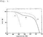
- Fig. 1 is a graph showing a result of a thermogravimetric analysis of a reaction product.
- a solid line A in the graph represents a behavior of the reaction product and broken lines B and C represent behaviors of the carbon nanofiber alone and TMSP-PMMA alone, respectively.
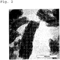
- TMSP-PMMA As a result of analyzing the graph, it was considered that about 5 parts by weight of TMSP-PMMA was grafted with respect to 100 parts by weight of the carbon nanofiber. Further, Fig. 2 is an electron microscope photograph of the grafted carbon nanofiber. As is clear from the photograph, it can be seen that a tubular carbon nanofiber at the center is coated with PMMA.
- unreacted TMSP-PMMA (about 95% of the added amount) was present in the reaction solution, but the unreacted TMSP-PMMA might be removed by an appropriate means.
- the reaction solution obtained above was used as it is for a preparation of the following coating composition.
- the unreacted TMSP-PMMA may have functions as a physical surface treatment agent.
- a predetermined amount of a liquid resol type phenol resin was gradually added at room temperature.
- ultrasonic treatment was performed in the same manner as described above, followed by stirring treatment at 10,000 rpm for about 20 minutes by using a commercially available homogenizer stirring apparatus (having 4 stirring blades), whereby the coating composition was obtained.
- 100 parts by weight of N-methyl-2-pyrrolidone, 5 parts by weight of the carbon nanofiber, and 5 parts by weight of (total of unreacted and reacted) TMSP-PMMA with respect to 100 parts by weight of the solid content of the phenol resin were used.
- an SPCC cold-rolled steel sheet degreased with ethyl alcohol (length: 150 mm, width: 70 mm, thickness: 0.8 mm) was used as a substrate.
- the coating composition was applied onto a whole surface of the substrate by spray method, and the resultant was subjected to heat treatment at about 200°C, whereby a coating film having a thickness of 40 to 50 ⁇ m was formed.
- the spray application was performed by using a pressure feed-type air spray gun (WIDER-61 manufactured by Iwata Tosoki K.K., nozzle diameter: 1.3 mm) under the following conditions: an air pressure of 0.29 to 0.34 MPa; and a coating composition discharge rate of 95 to 200 ml/min.
- the thickness of the coating film was measured in accordance with JIS K 5600-1-7 by using an electromagnetic coating thickness tester (LZ-330 manufactured by Kett Electric Laboratory). Further, a cross section of the coated article was observed by a scanning microscope and it was confirmed that there were no notable void and the like at an interface of the substrate and the coating film.
- an M20 bolt having a thread length of 100 mm and an M20 hexagonal nut having a height of 16 mm were used as the substrates, and a coating film was formed on a whole surface of each of the substrates in the same manner as described above.
- a cationic surfactant (Disperbyk-130 manufactured by BYK-Chemie) was used per 100 ml of N-methyl-2-pyrrolidone to prepare a surface treatment solution of the carbon nanofiber.
- a predetermined amount of the carbon nanofiber having a structure in which a plurality of carbon network layers each having a bottomless cup shape are laminated in a nested manner (manufactured by GSI Creos Corporation, trade name: Carbere (registered trademark)) was gradually added.
- the mixture was stirred for 2 to 3 minutes by using a stainless stirring rod, and surface treatment (surfactant treatment) of the carbon nanofiber was performed.
- ultrasonic waves are imparted to the mixture for about 30 minutes by using a commercially available ultrasonic generator (100 kHz), whereby dispersion and the surface treatment of the carbon nanofiber were promoted. Further, the resultant was stirred at 10,000 rpm for about 20 minutes by using the commercially available homogenizer stirring apparatus (having 4 stirring blades), whereby the dispersion and the surface treatment of the carbon nanofiber were further promoted. Thus, a dispersing element of dispersion medium/multilayer carbon nanofiber was prepared.
- a predetermined amount of the liquid resol type phenol resin was gradually added.
- the dispersion treatment was performed by the ultrasonic waves and the homogenizer in the same manner as described above, whereby a coating composition was obtained.
- 100 parts by weight of N-methyl-2-pyrrolidone and 4.73 parts by weight of the carbon nanofiber with respect to 100 parts by weight of the solid content of the phenol resin were used.
- the coating composition was used to form a coating film in the same manner as in Example 1.
- the obtained coating film was subjected to the same evaluation as in Example 1. Results thereof are shown in Table 1.
- a coating composition was prepared in the same manner as in Example 2 except that 11.05 parts by weight of the carbon nanofiber with respect to 100 parts by weight of the solid content of the phenol resin was used.
- the coating composition was used to form a coating film in the same manner as in Example 1.
- the obtained coating film was subjected to the same evaluation as in Example 1. Results thereof are shown in Table 1.
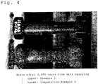
- a photograph showing a comparison between a state after 2,000 hours from salt spraying of the coated article obtained in Example 3 and a state after 2,000 hours from salt spraying of a coated article of Comparative Example 4 to be described below is shown in Fig. 4 .
- a coating composition was prepared in the same manner as in Example 2 except that 100 parts by weight of a polyamideimide resin (solid content) was used instead of 100 parts by weight of the phenol resin (solid content) and 4.55 parts by weight of the carbon nanofiber with respect to 100 parts by weight of the solid content of the polyamideimide resin was used.
- the coating composition was used to form a coating film in the same manner as in Example 1 except that the drying temperature was set to 180°C.
- the obtained coating film was subjected to the same evaluation as in Example 1. Results thereof are shown in Table 1.
- a coating composition was prepared in the same manner as in Example 4 except that 10.64 parts by weight of the carbon nanofiber with respect to 100 parts by weight of the solid content of the polyamideimide resin was used.
- the coating composition was used to form a coating film in the same manner as in Example 4.
- the obtained coating film was subjected to the same evaluation as in Example 1. Results thereof are shown in Table 1.
- a coating composition was prepared in the same manner as in Example 2 except that an anionic surfactant (manufactured by BYK-Chemie, trade name: Anti-Terre-206) was used instead of the cationic surfactant.
- the coating composition was used to form a coating film in the same manner as in Example 1.
- the obtained coating film was subjected to the same evaluation as in Example 1. Results thereof are shown in Table 1.
- a coating composition was prepared in the same manner as in Example 4 except that the anionic surfactant was used instead of the cationic surfactant.
- the coating composition was used to form a coating film in the same manner as in Example 1.
- the obtained coating film was subjected to the same evaluation as in Example 1. Results thereof are shown in Table 1.
- a coating composition was prepared in the same manner as in Example 2 except that 4.73 parts by weight of a carbon nanofiber having a structure in which a plurality of tubular carbon network layers each having a different diameter are arranged coaxially (VGCF (R) manufactured by SHOWA DENKO K.K.) was used instead of the carbon nanofiber having a structure in which a plurality of carbon network layers each having a bottomless cup shape are laminated in a nested manner.
- the coating composition was used to form a coating film in the same manner as in Example 1.
- the obtained coating film was subjected to the same evaluation as in Example 1. Results thereof are shown in Table 1.
- a coating composition was prepared in the same manner as in Example 4 except that 4.55 parts by weight of a carbon nanofiber having a structure in which a plurality of tubular carbon network layers each having a different diameter are arranged coaxially (VGCF (R) manufactured by SHOWA DENKO K.K.) was used instead of the carbon nanofiber having a structure in which a plurality of carbon network layers each having a bottomless cup shape are laminated in a nested manner.
- the coating composition was used to form a coating film in the same manner as in Example 4.
- the obtained coating film was subjected to the same evaluation as in Example 1. Results thereof are shown in Table 1.
- a coating composition was prepared in the same manner as in Example 2 except that 4.73 parts by weight of an ordinary single-layer carbon nanotube (SWCNT manufactured by CORENET INTERNATIONAL Corporation) was used instead of the carbon nanofiber having a structure in which a plurality of carbon network layers each having a bottomless cup shape are laminated in a nested manner.
- the coating composition was used to form a coating film in the same manner as in Example 1.
- the obtained coating film was subjected to the same evaluation as in Example 1. Results thereof are shown in Table 1.
- a coating composition was prepared in the same manner as in Comparative Example 1 except that 11.05 parts by weight of a single-layer carbon nanotube was used.
- the coating composition was used to form a coating film in the same manner as in Example 1.
- the obtained coating film was subjected to the same evaluation as in Example 1. Results thereof are shown in Table 1.
- a coating composition was prepared in the same manner as in Example 4 except that 4.55 parts by weight of the ordinary single-layer carbon nanotube (SWCNT manufactured by CORENET INTERNATIONAL Corporation) was used instead of the carbon nanofiber having a structure in which a plurality of carbon network layers each having a bottomless cup shape are laminated in a nested manner.
- the coating composition was used to form a coating film in the same manner as in Example 1.
- the obtained coating film was subjected to the same evaluation as in Example 1. Results thereof are shown in Table 1.
- a coating composition was prepared in the same manner as in Comparative Example 3 except that 10.64 parts by weight of the single-layer carbon nanotube was used.
- the coating composition was used to form a coating film in the same manner as in Example 1.
- the obtained coating film was subjected to the same evaluation as in Example 1. Results thereof are shown in Table 1.
- a photograph showing a state after 2,000 hours from salt spraying of the coated article obtained in Comparative Example 4 together with the state after 2,000 hours from salt spraying of the coated article of Example 3 is shown in Fig. 4
- a photograph showing a state after 24 hours from salt spraying of the coated article obtained in Comparative Example 4 is shown in Fig. 5 .
- a coating composition was prepared in the same manner as in Example 2 except that 4.73 parts by weight of carbon black was used instead of the carbon nanofiber having a structure in which a plurality of carbon network layers each having a bottomless cup shape are laminated in a nested manner.
- the coating composition was used to form a coating film in the same manner as in Example 1.
- the obtained coating film was subjected to the same evaluation as in Example 1. Results thereof are shown in Table 1.
- a coating composition was prepared in the same manner as in Example 4 except that 4.55 parts by weight of the carbon black was used instead of the carbon nanofiber having a structure in which a plurality of carbon network layers each having a bottomless cup shape are laminated in a nested manner.
- the coating composition was used to form a coating film in the same manner as in Example 4.
- the obtained coating film was subjected to the same evaluation as in Example 1. Results thereof are shown in Table 1.
- the coating compositions of the examples of the present invention each form a coating film which satisfies both the mechanical properties (in particular, pencil hardness and Knoop hardness) and the corrosion resistance (salt spray test) at the same time. More specifically, the improvement in the corrosion resistance of the coating compositions of the examples of the present invention is more remarkable compared with that of the coating compositions of Comparative Examples 1 to 4 each using the single-layer carbon nanofiber.
- Example 1 in which the carbon nanofiber having a structure in which a plurality of carbon network layers each having a bottomless cup shape are laminated in a nested manner and being grafted with PMMA is used and the coating compositions of Examples 2 to 5 which are subjected to the surface treatment with the cationic surfactant are incommensurably improved in the corrosion resistance compared with the coating compositions of Comparative Examples 1 to 4 each using the single-layer carbon nanofiber.
- the coating compositions of the examples of the present invention are remarkably improved in the mechanical properties (in particular, Knoop hardness, bending property, impact resistance, and rupture of coating film) compared with the coating compositions of Comparative Examples 5 and 6 each of which does not use the carbon nanofiber (and does use the carbon black).
- the coating composition of the present invention may be appropriately utilized for coating machine parts such as the metal industrial part, various fastening parts such as the bolt/nut, the shaft bearing, various sealing parts, the fastening flange, the washer, the brake shoe, the jack part, and the sliding part of semiconductor manufacturing equipment. Further, the coating composition of the present invention is also applicable to lining coating of various environmental deprivations.
Landscapes
- Chemical & Material Sciences (AREA)
- Engineering & Computer Science (AREA)
- Materials Engineering (AREA)
- Organic Chemistry (AREA)
- Wood Science & Technology (AREA)
- Life Sciences & Earth Sciences (AREA)
- Ceramic Engineering (AREA)
- Structural Engineering (AREA)
- Inorganic Chemistry (AREA)
- Nanotechnology (AREA)
- Civil Engineering (AREA)
- Chemical Kinetics & Catalysis (AREA)
- Laminated Bodies (AREA)
- Paints Or Removers (AREA)
- Chemical Or Physical Treatment Of Fibers (AREA)
- Treatments For Attaching Organic Compounds To Fibrous Goods (AREA)
Claims (9)
- Composition de revêtement, comprenant :• un liant en résine synthétique ;• une nanofibre de carbone multicouche soumise à un traitement de surface au moyen d'une substance non conductrice ; et• un milieu de dispersion,où la nanofibre de carbone multicouche est dotée d'une non-conductivité adéquate par le traitement de surface au moyen de la substance non conductrice, où le traitement de surface est un traitement physique au moyen d'un tensioactif cationique,
et
où la nanofibre de carbone multicouche présente une structure telle qu'une pluralité de couches de réseaux de carbone tubulaire ayant chacun un diamètre différent sont agencées de manière coaxiale. - Composition de revêtement, comprenant :• un liant en résine synthétique ;• une nanofibre de carbone multicouche soumise à un traitement de surface au moyen d'une substance non conductrice ; et• un milieu de dispersion,où la nanofibre de carbone multicouche est dotée d'une non-conductivité adéquate par le traitement de surface au moyen de la substance non conductrice,
où le traitement de surface est un traitement de surface chimique, où la nanofibre de carbone multicouche est greffée sur au moins une partie de sa surface par un procédé de greffage au moyen d'une substance à masse moléculaire faible ou élevée ayant un groupe trimethoxysilyl, et/ou
où le traitement de surface est un traitement physique au moyen d'un tensioactif cationique,
où la nanofibre de carbone multicouche présente une structure telle qu'une pluralité de couches de réseaux de carbone ayant chacun la forme d'une coupelle sans fond sont laminées de manière imbriquée, et
où une pellicule de revêtement à obtenir a une dureté Knoop (JIS Z 2251) de 20 Hk ou plus et une capacité de résistance à la corrosion déterminée par un essai au brouillard salin de 1000 heures ou plus. - Composition de revêtement selon la revendication 1 ou la revendication 2, où la composition de revêtement comprend 3 à 15 parties en poids de nanofibres de carbone multicouche et 10 à 300 parties en poids du milieu de dispersion pour 100 parties en poids du liant en résine synthétique.
- Composition de revêtement selon l'une quelconque des revendications 1 à 3, où le liant en résine synthétique comprend une résine thermodurcissable.
- Composition de revêtement selon l'une quelconque des revendications 1 à 4, où le liant en résine synthétique comprend au moins une résine choisie parmi le groupe comprenant une résine de phénol, une résine époxy, une résine polyuréthane, une résine de silicone, une résine polyamideimide et une résine fluorée à base d'eau.
- Composition de revêtement selon l'une quelconque des revendications 1 à 5, où le milieu de dispersion comprend un solvant polaire.
- Composition de revêtement selon la revendication 6, où le milieu de dispersion comprend au moins un élément choisi parmi le groupe comprenant l'eau, les alcools, la N-méthyl-2-pyrrolidone, le diméthylacétamide, la méthyléthylecétone, et la méthylisobutylcétone.
- Article revêtu, comprenant une pellicule de revêtement composée de la composition de revêtement selon l'une quelconque des revendications 1 à 7 sur au moins une partie d'une surface d'un substrat.
- Article revêtu selon la revendication 8, où le substrat est sélectionné parmi le groupe comprenant une pièce industrielle métallique, un boulon/écrou, un roulement d'arbre, une pièce d'étanchéité, une bride de fixation, une rondelle, un sabot de frein, une pièce de vérin et une pièce coulissante d'une installation de fabrication de semi-conducteurs.
Applications Claiming Priority (2)
| Application Number | Priority Date | Filing Date | Title |
|---|---|---|---|
| JP2006122801A JP4536031B2 (ja) | 2006-04-27 | 2006-04-27 | 被覆組成物および被覆物 |
| PCT/JP2007/059418 WO2007132684A1 (fr) | 2006-04-27 | 2007-04-25 | Composition de revetement et article revetu |
Publications (3)
| Publication Number | Publication Date |
|---|---|
| EP2011838A1 EP2011838A1 (fr) | 2009-01-07 |
| EP2011838A4 EP2011838A4 (fr) | 2010-04-14 |
| EP2011838B1 true EP2011838B1 (fr) | 2016-12-21 |
Family
ID=38693782
Family Applications (1)
| Application Number | Title | Priority Date | Filing Date |
|---|---|---|---|
| EP07742853.0A Active EP2011838B1 (fr) | 2006-04-27 | 2007-04-25 | Composition de revetement comprenant des nanofibres de carbone multicouches traités en surface |
Country Status (5)
| Country | Link |
|---|---|
| US (1) | US20100239838A1 (fr) |
| EP (1) | EP2011838B1 (fr) |
| JP (1) | JP4536031B2 (fr) |
| TW (1) | TW200800600A (fr) |
| WO (1) | WO2007132684A1 (fr) |
Families Citing this family (13)
| Publication number | Priority date | Publication date | Assignee | Title |
|---|---|---|---|---|
| FI20070886A0 (fi) * | 2007-11-21 | 2007-11-21 | Noella Oy | Menetelmä korroosion estämiseksi |
| FR2924133B1 (fr) * | 2007-11-26 | 2012-12-14 | Porcher Ind | Element de renfort longitudinal a base de fibres minerales ou organiques et son procede d'obtention |
| EP2246396B2 (fr) * | 2008-01-24 | 2022-07-13 | Yuken Industry Co., Ltd. | Composition de revêtement anti-corrosion et procédé de production d'élément à film de revêtement anti-corrosion utilisant la composition |
| CN102030987B (zh) * | 2009-09-30 | 2013-12-04 | E.I.内穆尔杜邦公司 | 抗腐蚀膜和包含该抗腐蚀膜的制品 |
| ITBS20100147A1 (it) * | 2010-08-31 | 2012-03-01 | Lucchini Rs Spa | Rivestimento protettivo per sale montate ferroviarie e metodo di applicazione |
| CZ2010913A3 (cs) * | 2010-12-09 | 2012-02-08 | Výzkumný ústav anorganické chemie, a. s. | Tekutá geopolymerní pryskyrice s nanovlákny a zpusob její výroby |
| CN102288352B (zh) * | 2011-07-20 | 2012-12-19 | 三一电气有限责任公司 | 一种测定螺栓扭矩系数的方法和装置 |
| JP2018002789A (ja) * | 2016-06-29 | 2018-01-11 | 株式会社東芝 | 複合材料および硬化性樹脂組成物 |
| CN106085137A (zh) * | 2016-08-04 | 2016-11-09 | 浙江无奇涂料有限公司 | 一种新型高硬度防腐涂料 |
| CN108532291A (zh) * | 2018-03-30 | 2018-09-14 | 陕西科技大学 | 一种碳布表面原位生长二氧化锰纳米片增强树脂基摩擦材料的制备方法 |
| CN110643255A (zh) * | 2019-09-05 | 2020-01-03 | 天恒涂料有限公司 | 一种环氧富锌石墨烯防腐涂料及其制备方法 |
| CN115368769A (zh) * | 2020-12-10 | 2022-11-22 | 熊秀 | 静电放电溶液及其制备方法和静电放电装置 |
| CN115160909B (zh) * | 2022-08-17 | 2023-01-06 | 广东邦固化学科技有限公司 | 一种五金表面仿搪瓷效果的水性耐高温涂料及其制备方法 |
Citations (1)
| Publication number | Priority date | Publication date | Assignee | Title |
|---|---|---|---|---|
| WO2005012171A2 (fr) * | 2003-07-28 | 2005-02-10 | William Marsh Rice University | Fonctionnalisation des parois laterales de nanotubes de carbone a l'aide d'organosilanes pour des composites a base de polymeres |
Family Cites Families (19)
| Publication number | Priority date | Publication date | Assignee | Title |
|---|---|---|---|---|
| JPH06122785A (ja) | 1991-12-10 | 1994-05-06 | Nikkiso Co Ltd | 導電性組成物、導電性塗料、導電性インク及び電気回路基板 |
| US6203814B1 (en) * | 1994-12-08 | 2001-03-20 | Hyperion Catalysis International, Inc. | Method of making functionalized nanotubes |
| JPH11263916A (ja) * | 1998-03-17 | 1999-09-28 | Fujitsu Ltd | 低誘電率の回路配線用絶縁材料及びこれを用いた電子部品 |
| US7264876B2 (en) * | 2000-08-24 | 2007-09-04 | William Marsh Rice University | Polymer-wrapped single wall carbon nanotubes |
| JP2002276665A (ja) | 2001-03-14 | 2002-09-25 | Ndc Co Ltd | 樹脂被覆摺動材 |
| JP3981567B2 (ja) | 2001-03-21 | 2007-09-26 | 守信 遠藤 | 炭素繊維の長さ調整方法 |
| CN1543399B (zh) * | 2001-03-26 | 2011-02-23 | 艾考斯公司 | 含碳纳米管的涂层 |
| US7118693B2 (en) * | 2001-07-27 | 2006-10-10 | Eikos, Inc. | Conformal coatings comprising carbon nanotubes |
| WO2003024798A1 (fr) * | 2001-09-18 | 2003-03-27 | Eikos, Inc. | Revetements dissipateurs d'electrostatique destines a etre utilises sur des engins spatiaux |
| JP3879991B2 (ja) * | 2002-06-03 | 2007-02-14 | 独立行政法人農業・食品産業技術総合研究機構 | ポリマー被覆カーボンナノチューブ |
| JP2004183127A (ja) * | 2002-12-02 | 2004-07-02 | Achilles Corp | 変性カーボンナノ繊維並びにこれを含む樹脂組成物及び塗料 |
| JP4005048B2 (ja) * | 2003-04-09 | 2007-11-07 | 日信工業株式会社 | 炭素繊維複合材料およびその製造方法 |
| JP2005007622A (ja) * | 2003-06-17 | 2005-01-13 | Takenaka Seisakusho:Kk | 機能性被膜が形成された被覆物及び機能性被覆剤並びに機能性被覆剤の製造方法 |
| JP4129209B2 (ja) | 2003-07-04 | 2008-08-06 | 株式会社Gsiクレオス | カーボンナノ材料 |
| JP4340489B2 (ja) | 2003-07-09 | 2009-10-07 | 株式会社竹中製作所 | 耐損傷性被膜が形成された被覆物及び耐損傷性被覆剤並びに耐損傷性被覆剤の製造方法 |
| JP2005163203A (ja) * | 2003-12-01 | 2005-06-23 | Norio Tsubokawa | 変性炭素繊維およびこれを含む樹脂組成物、塗料 |
| US20050186378A1 (en) * | 2004-02-23 | 2005-08-25 | Bhatt Sanjiv M. | Compositions comprising carbon nanotubes and articles formed therefrom |
| FR2870251B1 (fr) * | 2004-05-11 | 2010-09-17 | Arkema | Materiaux composites a base de nanotubes de carbone et matrices polymeres et leurs procedes d'obtention |
| JP4805820B2 (ja) * | 2004-05-13 | 2011-11-02 | 国立大学法人北海道大学 | 微小カーボン分散物 |
-
2006
- 2006-04-27 JP JP2006122801A patent/JP4536031B2/ja active Active
-
2007
- 2007-04-25 EP EP07742853.0A patent/EP2011838B1/fr active Active
- 2007-04-25 WO PCT/JP2007/059418 patent/WO2007132684A1/fr active Application Filing
- 2007-04-25 US US12/298,178 patent/US20100239838A1/en not_active Abandoned
- 2007-04-27 TW TW096114970A patent/TW200800600A/zh unknown
Patent Citations (1)
| Publication number | Priority date | Publication date | Assignee | Title |
|---|---|---|---|---|
| WO2005012171A2 (fr) * | 2003-07-28 | 2005-02-10 | William Marsh Rice University | Fonctionnalisation des parois laterales de nanotubes de carbone a l'aide d'organosilanes pour des composites a base de polymeres |
Also Published As
| Publication number | Publication date |
|---|---|
| TW200800600A (en) | 2008-01-01 |
| TWI377129B (fr) | 2012-11-21 |
| JP2007291280A (ja) | 2007-11-08 |
| WO2007132684A1 (fr) | 2007-11-22 |
| US20100239838A1 (en) | 2010-09-23 |
| EP2011838A4 (fr) | 2010-04-14 |
| JP4536031B2 (ja) | 2010-09-01 |
| EP2011838A1 (fr) | 2009-01-07 |
Similar Documents
| Publication | Publication Date | Title |
|---|---|---|
| EP2011838B1 (fr) | Composition de revetement comprenant des nanofibres de carbone multicouches traités en surface | |
| Ding et al. | A long-term anticorrsive coating through graphene passivation | |
| US9683109B2 (en) | Self healing anti corrosive coatings and a process for the preparation thereof | |
| EP2360216B1 (fr) | Composition de résine pour le traitement de tôle d'acier et tôle d'acier traitée en surface comprenant cette composition de résine | |
| EP2931818B1 (fr) | Procédé pour doter des substrats métalliques d'une résistance à la corrosion | |
| JP2012520355A (ja) | カーボンナノチューブを充填した、uv硬化性で耐摩耗性の帯電防止コーティング | |
| CN108624195B (zh) | 一种g-C3N4-G/水性环氧复合涂料的制备方法 | |
| DE102009052399A1 (de) | Korrosionsschutzbeschichtungen, insbesondere für Aluminium, und Mischungen zu ihrer Herstellung | |
| Beryl et al. | Electrochemical and mechanical studies of epoxy coatings containing eco-friendly nanocomposite consisting of silane functionalized clay–epoxy on mild steel | |
| Dermanaki Farahani et al. | Electrically conductive silver nanoparticles‐filled nanocomposite materials as surface coatings of composite structures | |
| Wang et al. | Designing BN@ CF hybrid to enhance the epoxy resin towards outstanding anti-corrosion and anti-wear performances | |
| Nazarlou et al. | Ti3C2 MXene/polyaniline/montmorillonite nanostructures toward solvent-free powder coatings with enhanced corrosion resistance and mechanical properties | |
| US20220056282A1 (en) | Electrically conductive coating compositions with corrosion resistance | |
| KR20200013841A (ko) | 콘크리트용 에폭시 도료 및 그를 이용한 건설구조물 보수 보강재 | |
| Xavier et al. | Carbon nanotube‐based polymer nanocomposites: Evaluation of barrier, hydrophobic, and mechanical properties for aerospace applications | |
| RU2318851C2 (ru) | Электропроводный лакокрасочный материал для антикоррозионной защиты металлических конструкций | |
| JP2005007622A (ja) | 機能性被膜が形成された被覆物及び機能性被覆剤並びに機能性被覆剤の製造方法 | |
| KR100796157B1 (ko) | 대전방지용 조성물 | |
| Ashok Kumar et al. | An insight on the corrosive performance of acrylic-epoxy based coatings: the significance of its electrochemical impedance evaluations | |
| JP2005028802A (ja) | 耐損傷性被膜が形成された被覆物及び耐損傷性被覆剤並びに耐損傷性被覆剤の製造方法 | |
| Thuy | Effects of additives, pigment and filler on physico-mechanical properties and weather resistance of polyurea coatings | |
| JP2008144185A (ja) | 被覆組成物および被覆物 | |
| CN115612330B (zh) | 一种巯基改性纳米银颗粒分散液的制备及其应用 | |
| Mardani et al. | Influence of MA‐g‐HDPE compatibilizer content on quality and adhesion/bending strength of polyethylene/O‐MMT coating films | |
| KR101165318B1 (ko) | 다이아몬드를 포함한 금속표면 처리용 조성물로 처리된 강판 |
Legal Events
| Date | Code | Title | Description |
|---|---|---|---|
| PUAI | Public reference made under article 153(3) epc to a published international application that has entered the european phase |
Free format text: ORIGINAL CODE: 0009012 |
|
| 17P | Request for examination filed |
Effective date: 20081023 |
|
| AK | Designated contracting states |
Kind code of ref document: A1 Designated state(s): AT BE BG CH CY CZ DE DK EE ES FI FR GB GR HU IE IS IT LI LT LU LV MC MT NL PL PT RO SE SI SK TR |
|
| AX | Request for extension of the european patent |
Extension state: AL BA HR MK RS |
|
| RIN1 | Information on inventor provided before grant (corrected) |
Inventor name: INAGAKI, HIROSHI Inventor name: KUROYAMA, SHOJI |
|
| RIN1 | Information on inventor provided before grant (corrected) |
Inventor name: KUROYAMA, SHOJI Inventor name: INAGAKI, HIROSHI |
|
| A4 | Supplementary search report drawn up and despatched |
Effective date: 20100311 |
|
| RIC1 | Information provided on ipc code assigned before grant |
Ipc: F16B 33/00 20060101ALI20100305BHEP Ipc: B32B 27/20 20060101ALI20100305BHEP Ipc: C09D 5/08 20060101ALI20100305BHEP Ipc: C09D 7/12 20060101AFI20080211BHEP Ipc: B32B 15/08 20060101ALI20100305BHEP |
|
| 17Q | First examination report despatched |
Effective date: 20110512 |
|
| DAX | Request for extension of the european patent (deleted) | ||
| GRAP | Despatch of communication of intention to grant a patent |
Free format text: ORIGINAL CODE: EPIDOSNIGR1 |
|
| INTG | Intention to grant announced |
Effective date: 20160721 |
|
| RIN1 | Information on inventor provided before grant (corrected) |
Inventor name: KUROYAMA, SHOJI Inventor name: INAGAKI, HIROSHI |
|
| GRAS | Grant fee paid |
Free format text: ORIGINAL CODE: EPIDOSNIGR3 |
|
| GRAA | (expected) grant |
Free format text: ORIGINAL CODE: 0009210 |
|
| RAP1 | Party data changed (applicant data changed or rights of an application transferred) |
Owner name: INAGAKI, KAZUKO Owner name: GSI CREOS CORPORATION Owner name: TAKENAKA SEISAKUSHO CO., LTD. |
|
| AK | Designated contracting states |
Kind code of ref document: B1 Designated state(s): AT BE BG CH CY CZ DE DK EE ES FI FR GB GR HU IE IS IT LI LT LU LV MC MT NL PL PT RO SE SI SK TR |
|
| REG | Reference to a national code |
Ref country code: GB Ref legal event code: FG4D |
|
| REG | Reference to a national code |
Ref country code: CH Ref legal event code: EP |
|
| REG | Reference to a national code |
Ref country code: IE Ref legal event code: FG4D |
|
| REG | Reference to a national code |
Ref country code: AT Ref legal event code: REF Ref document number: 855485 Country of ref document: AT Kind code of ref document: T Effective date: 20170115 |
|
| REG | Reference to a national code |
Ref country code: DE Ref legal event code: R096 Ref document number: 602007049232 Country of ref document: DE |
|
| PG25 | Lapsed in a contracting state [announced via postgrant information from national office to epo] |
Ref country code: LV Free format text: LAPSE BECAUSE OF FAILURE TO SUBMIT A TRANSLATION OF THE DESCRIPTION OR TO PAY THE FEE WITHIN THE PRESCRIBED TIME-LIMIT Effective date: 20161221 |
|
| REG | Reference to a national code |
Ref country code: FR Ref legal event code: PLFP Year of fee payment: 11 |
|
| REG | Reference to a national code |
Ref country code: LT Ref legal event code: MG4D |
|
| REG | Reference to a national code |
Ref country code: NL Ref legal event code: MP Effective date: 20161221 |
|
| PG25 | Lapsed in a contracting state [announced via postgrant information from national office to epo] |
Ref country code: GR Free format text: LAPSE BECAUSE OF FAILURE TO SUBMIT A TRANSLATION OF THE DESCRIPTION OR TO PAY THE FEE WITHIN THE PRESCRIBED TIME-LIMIT Effective date: 20170322 Ref country code: SE Free format text: LAPSE BECAUSE OF FAILURE TO SUBMIT A TRANSLATION OF THE DESCRIPTION OR TO PAY THE FEE WITHIN THE PRESCRIBED TIME-LIMIT Effective date: 20161221 Ref country code: LT Free format text: LAPSE BECAUSE OF FAILURE TO SUBMIT A TRANSLATION OF THE DESCRIPTION OR TO PAY THE FEE WITHIN THE PRESCRIBED TIME-LIMIT Effective date: 20161221 |
|
| REG | Reference to a national code |
Ref country code: AT Ref legal event code: MK05 Ref document number: 855485 Country of ref document: AT Kind code of ref document: T Effective date: 20161221 |
|
| PG25 | Lapsed in a contracting state [announced via postgrant information from national office to epo] |
Ref country code: FI Free format text: LAPSE BECAUSE OF FAILURE TO SUBMIT A TRANSLATION OF THE DESCRIPTION OR TO PAY THE FEE WITHIN THE PRESCRIBED TIME-LIMIT Effective date: 20161221 |
|
| PG25 | Lapsed in a contracting state [announced via postgrant information from national office to epo] |
Ref country code: NL Free format text: LAPSE BECAUSE OF FAILURE TO SUBMIT A TRANSLATION OF THE DESCRIPTION OR TO PAY THE FEE WITHIN THE PRESCRIBED TIME-LIMIT Effective date: 20161221 |
|
| PG25 | Lapsed in a contracting state [announced via postgrant information from national office to epo] |
Ref country code: CZ Free format text: LAPSE BECAUSE OF FAILURE TO SUBMIT A TRANSLATION OF THE DESCRIPTION OR TO PAY THE FEE WITHIN THE PRESCRIBED TIME-LIMIT Effective date: 20161221 Ref country code: RO Free format text: LAPSE BECAUSE OF FAILURE TO SUBMIT A TRANSLATION OF THE DESCRIPTION OR TO PAY THE FEE WITHIN THE PRESCRIBED TIME-LIMIT Effective date: 20161221 Ref country code: EE Free format text: LAPSE BECAUSE OF FAILURE TO SUBMIT A TRANSLATION OF THE DESCRIPTION OR TO PAY THE FEE WITHIN THE PRESCRIBED TIME-LIMIT Effective date: 20161221 Ref country code: IS Free format text: LAPSE BECAUSE OF FAILURE TO SUBMIT A TRANSLATION OF THE DESCRIPTION OR TO PAY THE FEE WITHIN THE PRESCRIBED TIME-LIMIT Effective date: 20170421 Ref country code: SK Free format text: LAPSE BECAUSE OF FAILURE TO SUBMIT A TRANSLATION OF THE DESCRIPTION OR TO PAY THE FEE WITHIN THE PRESCRIBED TIME-LIMIT Effective date: 20161221 |
|
| PG25 | Lapsed in a contracting state [announced via postgrant information from national office to epo] |
Ref country code: BE Free format text: LAPSE BECAUSE OF FAILURE TO SUBMIT A TRANSLATION OF THE DESCRIPTION OR TO PAY THE FEE WITHIN THE PRESCRIBED TIME-LIMIT Effective date: 20161221 Ref country code: BG Free format text: LAPSE BECAUSE OF FAILURE TO SUBMIT A TRANSLATION OF THE DESCRIPTION OR TO PAY THE FEE WITHIN THE PRESCRIBED TIME-LIMIT Effective date: 20170321 Ref country code: ES Free format text: LAPSE BECAUSE OF FAILURE TO SUBMIT A TRANSLATION OF THE DESCRIPTION OR TO PAY THE FEE WITHIN THE PRESCRIBED TIME-LIMIT Effective date: 20161221 Ref country code: PT Free format text: LAPSE BECAUSE OF FAILURE TO SUBMIT A TRANSLATION OF THE DESCRIPTION OR TO PAY THE FEE WITHIN THE PRESCRIBED TIME-LIMIT Effective date: 20170421 Ref country code: PL Free format text: LAPSE BECAUSE OF FAILURE TO SUBMIT A TRANSLATION OF THE DESCRIPTION OR TO PAY THE FEE WITHIN THE PRESCRIBED TIME-LIMIT Effective date: 20161221 Ref country code: IT Free format text: LAPSE BECAUSE OF FAILURE TO SUBMIT A TRANSLATION OF THE DESCRIPTION OR TO PAY THE FEE WITHIN THE PRESCRIBED TIME-LIMIT Effective date: 20161221 Ref country code: AT Free format text: LAPSE BECAUSE OF FAILURE TO SUBMIT A TRANSLATION OF THE DESCRIPTION OR TO PAY THE FEE WITHIN THE PRESCRIBED TIME-LIMIT Effective date: 20161221 |
|
| REG | Reference to a national code |
Ref country code: DE Ref legal event code: R097 Ref document number: 602007049232 Country of ref document: DE |
|
| PLBE | No opposition filed within time limit |
Free format text: ORIGINAL CODE: 0009261 |
|
| STAA | Information on the status of an ep patent application or granted ep patent |
Free format text: STATUS: NO OPPOSITION FILED WITHIN TIME LIMIT |
|
| REG | Reference to a national code |
Ref country code: DE Ref legal event code: R079 Ref document number: 602007049232 Country of ref document: DE Free format text: PREVIOUS MAIN CLASS: C09D0007120000 Ipc: C09D0007400000 |
|
| 26N | No opposition filed |
Effective date: 20170922 |
|
| PG25 | Lapsed in a contracting state [announced via postgrant information from national office to epo] |
Ref country code: DK Free format text: LAPSE BECAUSE OF FAILURE TO SUBMIT A TRANSLATION OF THE DESCRIPTION OR TO PAY THE FEE WITHIN THE PRESCRIBED TIME-LIMIT Effective date: 20161221 |
|
| REG | Reference to a national code |
Ref country code: CH Ref legal event code: PL |
|
| REG | Reference to a national code |
Ref country code: IE Ref legal event code: MM4A |
|
| PG25 | Lapsed in a contracting state [announced via postgrant information from national office to epo] |
Ref country code: MC Free format text: LAPSE BECAUSE OF FAILURE TO SUBMIT A TRANSLATION OF THE DESCRIPTION OR TO PAY THE FEE WITHIN THE PRESCRIBED TIME-LIMIT Effective date: 20161221 |
|
| PG25 | Lapsed in a contracting state [announced via postgrant information from national office to epo] |
Ref country code: SI Free format text: LAPSE BECAUSE OF FAILURE TO SUBMIT A TRANSLATION OF THE DESCRIPTION OR TO PAY THE FEE WITHIN THE PRESCRIBED TIME-LIMIT Effective date: 20161221 Ref country code: LI Free format text: LAPSE BECAUSE OF NON-PAYMENT OF DUE FEES Effective date: 20170430 Ref country code: LU Free format text: LAPSE BECAUSE OF NON-PAYMENT OF DUE FEES Effective date: 20170425 Ref country code: CH Free format text: LAPSE BECAUSE OF NON-PAYMENT OF DUE FEES Effective date: 20170430 |
|
| REG | Reference to a national code |
Ref country code: FR Ref legal event code: PLFP Year of fee payment: 12 |
|
| PG25 | Lapsed in a contracting state [announced via postgrant information from national office to epo] |
Ref country code: IE Free format text: LAPSE BECAUSE OF NON-PAYMENT OF DUE FEES Effective date: 20170425 |
|
| PG25 | Lapsed in a contracting state [announced via postgrant information from national office to epo] |
Ref country code: MT Free format text: LAPSE BECAUSE OF NON-PAYMENT OF DUE FEES Effective date: 20170425 |
|
| PG25 | Lapsed in a contracting state [announced via postgrant information from national office to epo] |
Ref country code: HU Free format text: LAPSE BECAUSE OF FAILURE TO SUBMIT A TRANSLATION OF THE DESCRIPTION OR TO PAY THE FEE WITHIN THE PRESCRIBED TIME-LIMIT; INVALID AB INITIO Effective date: 20070425 |
|
| PG25 | Lapsed in a contracting state [announced via postgrant information from national office to epo] |
Ref country code: CY Free format text: LAPSE BECAUSE OF NON-PAYMENT OF DUE FEES Effective date: 20161221 |
|
| PG25 | Lapsed in a contracting state [announced via postgrant information from national office to epo] |
Ref country code: TR Free format text: LAPSE BECAUSE OF FAILURE TO SUBMIT A TRANSLATION OF THE DESCRIPTION OR TO PAY THE FEE WITHIN THE PRESCRIBED TIME-LIMIT Effective date: 20161221 |
|
| PGFP | Annual fee paid to national office [announced via postgrant information from national office to epo] |
Ref country code: FR Payment date: 20230420 Year of fee payment: 17 Ref country code: DE Payment date: 20230420 Year of fee payment: 17 |
|
| PGFP | Annual fee paid to national office [announced via postgrant information from national office to epo] |
Ref country code: GB Payment date: 20230419 Year of fee payment: 17 |