EP2008545B1 - Applicateur pour liquide - Google Patents
Applicateur pour liquide Download PDFInfo
- Publication number
- EP2008545B1 EP2008545B1 EP07737811A EP07737811A EP2008545B1 EP 2008545 B1 EP2008545 B1 EP 2008545B1 EP 07737811 A EP07737811 A EP 07737811A EP 07737811 A EP07737811 A EP 07737811A EP 2008545 B1 EP2008545 B1 EP 2008545B1
- Authority
- EP
- European Patent Office
- Prior art keywords
- liquid
- application
- applying part
- main body
- applying
- Prior art date
- Legal status (The legal status is an assumption and is not a legal conclusion. Google has not performed a legal analysis and makes no representation as to the accuracy of the status listed.)
- Active
Links
Images


Classifications
-
- B—PERFORMING OPERATIONS; TRANSPORTING
- B43—WRITING OR DRAWING IMPLEMENTS; BUREAU ACCESSORIES
- B43K—IMPLEMENTS FOR WRITING OR DRAWING
- B43K1/00—Nibs; Writing-points
-
- A—HUMAN NECESSITIES
- A45—HAND OR TRAVELLING ARTICLES
- A45D—HAIRDRESSING OR SHAVING EQUIPMENT; EQUIPMENT FOR COSMETICS OR COSMETIC TREATMENTS, e.g. FOR MANICURING OR PEDICURING
- A45D34/00—Containers or accessories specially adapted for handling liquid toiletry or cosmetic substances, e.g. perfumes
- A45D34/04—Appliances specially adapted for applying liquid, e.g. using roller or ball
-
- B—PERFORMING OPERATIONS; TRANSPORTING
- B43—WRITING OR DRAWING IMPLEMENTS; BUREAU ACCESSORIES
- B43K—IMPLEMENTS FOR WRITING OR DRAWING
- B43K8/00—Pens with writing-points other than nibs or balls
Definitions
- the present invention relates to a liquid applicator which is provided with liquid pressing means for pressurizing an application liquid within a main body, and feeds an applying part at the front end of the main body with the application liquid by pressing of the liquid pressing means, and particularly relates to a liquid applicator for applying an application liquid to a soft object to be applied such as skin and oral cavity.
- a liquid applicator for applying an application liquid such as cosmetics and a chemical liquid
- a liquid pressing mechanism or liquid pressing means which has a piston for pressurizing the application liquid in an application liquid reservoir provided within the main body to store the application liquid in the main body and appropriately supply an applying part provided at the front end with the application liquid, and an advance mechanism thereof
- Japanese Patent No. 3081834 Patent Document 1
- Japanese Utility Model Registration No. 2603088 Patent Document 2
- an applying part of an applicator for cosmetics that is provided with an application spatula being projected frontward from a discharge port (an ejection port) of an application liquid is disclosed (Japanese Utility Model Application Laid-Open Sho 61 No.
- Patent Document 3 Patent Document 3
- an application liquid for cosmetics is supplied to the application spatula from the discharge port and the application liquid is applied and spread with the application spatula being elastically deformed.
- an applicator for liquid cosmetics is proposed, that a main body of an application portion composed of a flexible silicone resin is provided with a contact surface so as to be inclined with respect to an outer end surface of the application portion (Japanese Utility Model Registration No. 3109917 : Patent Document 4).
- Japanese Utility Model Registration No. 3109917 Patent Document 4
- the ejection port in the main body of the application portion is deformed with a pressure of pressurized and fed cosmetics to discharge the cosmetic liquid, and the flexible main body of the application portion provides comfortable contact feeling at the time of application and enables uniform spreading.
- the present invention has been made to solve such problems, and it is an object of the invention to provide a liquid applicator in which an applying part has an appropriate hardness and bending elastic force, having no application unevenness and excellent application characteristics.
- the present invention provides a liquid applicator which comprises liquid pressing means for pressurizing an application liquid within a main body, and supplies an applying part at a front end of the main body with the application liquid by pressing of the liquid pressing means, wherein the applying part is made of an elastic material, formed with a communication channel for connecting inside and outside of the main body, and is provided with an application portion further protruding to a front end from an ejection port of the communication path, and the application portion has a vertical-direction repulsion force of 0.01 to 1.40 (N) at a portion 3 (mm) from the front end.
- a distance L from the ejection port to the front end is within a dimension range of 1 ⁇ L ⁇ 20 (mm), and a width W from the ejection port to the front end is within a dimension range of 2 ⁇ W ⁇ 20 (mm).
- the applying part is made of a transparent or translucent material so that an application liquid (such as an ink) in the communication channel can be visually observed. Further, by making the applying part colored translucent, an application liquid can be visually viewed, as well as, following effects (i) or (ii) can be attained.
- an applying part made of an elastic material is formed with a communication channel for connecting the inside and the outside of a main body, and is provided with an application portion so as to further protrude to a front end from an ejection port of the communication path, wherein the application portion has a vertical-direction repulsion force of 0.01 to 1.4 (N) at a portion 3 (mm) from the front end, and thereby an excellent operative effect that the applying part is provided so as to have an excellent usability and no application unevenness, can be obtained.
- the application portion of the applying part is provided so that a portion 3 (mm) from the front end thereof has a vertical-direction repulsion force of 0.01 to 0.70 (N), and thereby it is possible to provide an applying part having further excellent usability and less application unevenness.
- the application liquid has viscosity in the range of 1,000 (mPs) to 100,000 (mPs)
- an applying part having no application unevenness and excellent application characteristics can be provided.
- the application portion of the applying part when exceeding conditions that a distance L from the ejection port to the front end is in a dimension range of 1 ⁇ L ⁇ 20 (mm) and a width W from the ejection port to the front end is within a dimension range of 2 ⁇ W ⁇ 20 (mm), it is difficult to perform application to a surface of a target object, and, by contraries, when being within the conditions, the application characteristics become excellent.
- the width and the length of the applying part are appropriately selected within the above conditions.
- the applying part is made of a transparent or translucent material so that the application liquid in the communication channel can be visually observed, resulting that even when the application liquid tank in the main body can not be observed, the color of the application liquid supplied to the applying part can be observed by seeing through the transparent or translucent applying part. Moreover, it is possible to visually confirm the state of the application liquid being fed and prevent overfeed of the application liquid at the start of use.
- FIGS. 1 to 16 are illustrative diagrams of each example of embodiments of a liquid applicator according to the present invention, where parts to which same reference numerals are given represent same parts.
- FIG. 1 is an overall view of a liquid applicator according to an embodiment 1
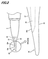
- FIG. 2 is a detailed illustrative view of an applying part.
- a liquid applicator 1 is provided with a liquid pressing mechanism (liquid pressing means) 6 for pressurizing an application liquid 4 within a main body 2, and in the liquid applicator 1 which is provided so that the application liquid 4 is supplied to an applying part 10 at the front end of the main body by pressing of the liquid pressing mechanism 6, the applying part 10 is made of an elastic material, is formed with a communication channel 24 for connecting the inside and the outside of the main body, and is provided with an application portion 10a so as to further protrude toward the front end from an ejection port 24a of the communication channel 24, and the application portion 10a has vertical-direction repulsion force of 0.01 to 1.40 (N) at a portion 3 mm from the front end.
- a liquid pressing mechanism liquid pressing means
- a distance L from the ejection port 24a to the front end is within a dimension range of 1 ⁇ L ⁇ 20 (mm), and a width W from the ejection port 24a to the front end is within a dimension range of 2 ⁇ W ⁇ 20 (mm).
- the applying part 10 is made of a transparent or translucent material so that ink in the communication channel 24 can be visually observed.
- the liquid applicator 1 is provided with the applying part 10 at the front end of the cylindrical main body 2, wherein the application liquid 4 stored in the reservoir space (reservoir tank) 2b within the main body 2 is pressurized by the liquid pressing mechanism 6 attached to the main body so that the application liquid 4 is supplied to the applying part 10 at the front end.
- the liquid pressing mechanism 6 is added with a function of capable of depressurizing so as to be a liquid pressurizing/depressurizing mechanism, by which the application liquid 4 can be selectively pushed out and returned.
- the liquid pressing mechanism 6 has a piston part 35 for reducing and increasing the volume in the reservoir space by moving back and forth toward the application liquid reservoir space 2b within the main body 2, and a driving mechanism (composed of a rotary operation member 31, a barrel member 32, a screw part 34, an advance part and the like) for engaging a front portion of the barrel member (referred to also as "the thread rod") 32 with a rear portion of the piston part 35 so that the piston part 35 is caused to advance and retreat by moving the barrel member 32 back and force with operation force of a user.
- a driving mechanism composed of a rotary operation member 31, a barrel member 32, a screw part 34, an advance part and the like
- the liquid applicator 1 is constituted by the outer cylindrical main body 2, a front barrel 3, the application liquid 4, the liquid pressing mechanism 6, a cap 7, and the applying part 10, as main members.
- the applying part 10 is molded with an elastic resin material, such as a rubber, an elastomer, or closed-cell foam objects, so as to be able to obtain required application characteristics, and members other than the applying part 10 are set so as to have a density and rigidity capable of obtaining required hermetic performance and supporting performance, and are made of a resinous material or a metalic material.
- an elastic resin material such as a rubber, an elastomer, or closed-cell foam objects
- a tapered small-diametric portion 2a of the main body is formed at the front end thereof, and the cap 7 is mated with the small-diametric portion 2a of the main body so as to be attachable and detachable.
- a space portion surrounded by a rear end of the front barrel 3 and the piston part 35 within the main body 2 serves as the application liquid reservoir space (ink tank) 2b.
- the piston part 35 is moved back and forth within the main body 2 by the liquid pressing mechanism 6, and thereby the volume in the application liquid reservoir space 2b is reduced and the pressure is increased so that the application liquid 4 is fed out in a direction of the application part.
- the liquid pressing mechanism 6 is constituted by the rotary operation member 31, the barrel member 32, the screw part 34 of the barrel member 32, and the aforementioned piston part 35, as main members.
- the rotary operation member 31 (in which a front end of the advance part 37 is fitted into the rear end of the main body 2 and a cylindrical knob 31a for operation is fitted into the rear end of the advance part 37 so as to be able to relatively rotate with a rotating force not less than a predetermined rotating force) is provided in the main body 2 so as to be rotatable entirely, and the annular screw part 34 is provided in the main body 2 so as not to be rotatable.
- An engaging portion 38 of the screw part 34 and the rotary operation member 31 (the advance part 37) is formed with a toothed ratchet, and rotation is regulated so that the rotary operation member 31 rotates in only one direction with respect to the screw part 34. Moreover, in the case of serving as the pressurizing/depressurizing mechanism, the rotation regulation is not performed so as to produce click feeling.
- a male thread in an outer periphery of the barrel member 32 is fitted with a female thread which is formed at a center hole of the screw part 34.
- the barrel member 32 has a dissimilar cam shape in a cross-sectional view, a center hole at an engagement portion 39 of the advance part 37 in the rotary operation member 31 is formed into a dissimilar cam shape corresponding to the outer periphery of the barrel member 32, and the barrel member 32 is inserted into the center hole of the engagement portion 39 so that barrel member 32 is slidable and relatively unrotatable in an axial direction with respect to the rotary operation member 31.
- the front end of the barrel member 32 is joined to the piston part 35, and when being rotated in a predetermined direction of the rotary operation member (a right rotating direction in the embodiment), the barrel member 32 advances with the piston part 35 by way of the screw part 34 toward the direction of the front end of the main body 2, and the application liquid 4 within (the application liquid reservoir space 2b of) the main body 2 is pressurized by the advance of the piston part 35 to be fed to the applying part 10.
- a predetermined direction of the rotary operation member a right rotating direction in the embodiment
- the front barrel 3 is formed so as to have a cylindrical structure where the diameter is reduced to taper, and the applying part 10 is stored in the internal space which is opened in its front and rear in a state where the front end thereof is being protruded and fixed to the main body 2 in this storage state.
- An annular fitting recess 3a which is formed on the outer periphery in the rear part of the front barrel 3 is press fitted into a fitting projection which is formed on the inner surface of a small-diametric portion of the main body 2a so as to prevent the front barrel 3 from dropping off from the main body 2.
- a flange 3b on the outer periphery of the front barrel 3 abuts the front end face of the small-diametric portion of the main body 2a.
- a pipe joint 12 is fitted into the inside of the rear part of the front barrel 3, and the front end of the pipe joint 12 and the step part inside the front barrel holds a flange-like portion in the rear end of the applying part 10 therebetween so as to position the applying part 10.
- a hollow pipe part 13 is fitted from the hollow inner peripheral part of the pipe joint 12 into the hollow part of the applying part 10, and the front end of the hollow part in the applying part 10 is connected to the communication channel 24.
- the applying part 10 of the liquid applicator 1 is made of an elastic material, and as shown in FIGS. 1 to 2 , the applying part 10 is formed with the communication channel 24 for connecting the inside of the main body 2 and the outside, and when the application liquid 4 is pressurized by the liquid pressing mechanism 6, the application liquid is fed from the pipe joint 12 and the pipe part 13 through the communication channel 24 to the application portion 10a.
- the front end which protrudes from the frontward of the front barrel 3 to be exposed has both-sided (upper-face and lower-face) taper portions 21 and 22 with a flat and tapered shape.
- the ejection port 24a of the communication channel 24 is opened in the upper-face taper portion 21.
- the application portion 10a of the applying part 10 is provided so as to further protrude toward the front end from the ejection port 24a of the communication channel 24.
- the applying part 10 may be an elastic body as a whole, or only the application portion 10a may be constituted by an elastic body.
- a material which is made of an elastic material including elastic materials such as a rubber and an elastomer, can be mentioned.
- any elastic body having no open cell can be used as long as it has liquid tightness.
- Examples thereof include:
- the application portion 10a is a portion which extends further frontward from the opening position of the ejection port 24a, and is formed as a flat portion 25.
- the communication channel 24 extends straightly in the axial direction from the front barrel 3 and is bent into a "projected V-shape" in the side of the upper-face taper portion 21 in the vicinity of the upper-face taper portion 21 to be exposed, and the ejection port 24a is opened.
- the communication channel 24 and the ejection port 24a have a semicircular cross sectional shape.
- the application liquid 4 in the application liquid reservoir space 2b is pressurized. With the pressure, the application liquid 4 is ejected from the ejection port 24a of the communication channel 24. The ejected application liquid 4 is once ejected to the side of the upper-face taper portion 21, and flows to the side of the flat portion 25 to be held in the flat portion 25 temporarily.
- the holding amount of the application liquid 4 in the flat portion 25 depends on a kind of cosmetics used.
- the applying part 10 is made of a transparent or colored translucent material so that ink in the communication channel 24 can be visually observed.
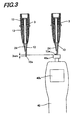
- FIG. 3 is an illustrative view of setting repulsion force of the applying part 10
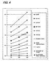
- FIG. 4 is an illustrative view of measuring repulsion force in comparative examples 1 to 2 and examples 1 to 9 where various kinds of materials are used for the applying part 10
- FIG. 5 is a view illustrating an example of measurement result in feeling of use and application unevenness in the comparative examples 1 to 2 and examples 1 to 8,
- FIG. 6 is an illustrative view of a method for evaluating application unevenness
- FIG. 7 is an illustrative view of a reference for evaluating application unevenness
- FIG. 8 is an illustrative view of a width W of the applying part and a length from an application portion
- FIG. 9 is an illustrative view of an evaluation of application unevenness.
- the applying part 10 of the embodiment is set so that the application portion 10a thereof has vertical-direction repulsion force of 0.01 to 1.40 (N) at a portion 3 mm from the front end thereof.
- the repulsion force of the application portion 10a was, as shown in FIG. 3 , detected by a force gauge 40.
- a detection edge 40a with a tray retreats by the strength of applied force to detect the force (display a numeric value (N) on a display portion 40b).
- each applying part was formed using each resin product (Q100F to an elastomer trial material) as a material.
- a portion 3 mm from the front end of the application portion is made contact with the detection edge 40a by sliding from a lateral direction (a vertical direction in advancing/retreating directions of the detection edge 40a), and under the state of which the force N that the application portion receives from the detection edge 40a was measured.
- each applying part was created by changing a material (a shape) as well.
- Comparative example 1 flexible polypropylene (flexible PP: trade name of Catalloy, and grade name of Q100F manufactured by SunAllomer Ltd., was used)
- Comparative example 2 Data 5 (thermoplastic resin product)
- thermoplastic resin product to create an applying part so that elastic force positioned between resin products used for each example is obtained in the force (N) applied from an application portion.
- a bulk 44 was dropped on a non-absorbent surface 42 having a thickness of 3 (mm) and an applying part was moved along the non-absorbent surface at constant speed, and thereby the bulk is applied and spread by the the applying part 10.
- the applying part was moved at a higher speed (150mm / sec) and at a lower speed (50mm / sec).
- the application portion is provided so that a portion 3 (mm) from the front end thereof has vertical-direction repulsion force of 0,01 to 1,4 (N), and thereby it is possible to provide an applying part having good usability and less application unevenness.
- the application portion of the applying part is provided so that a portion 3 (mm) from the front end thereof has vertical-direction repulsion force of 0.01 to 0.70 (N), and thereby it is possible to provide an applying part with further good usability and less application unevenness.
- the application liquid has viscosity in the range of 1,000 (mPs) to 100.000 (mPs)
- an applying part having no application unevenness and good application characteristics is provided.
- width W and the length L of the application part 10a are appropriately selected in accordance with application objects within the above ranges.
- the applying part 10 is made of a transparent or translucent material so that ink in the communication channel can be visually observed. It is more preferable to make translucent by coloring in a color different from that of an application liquid.
- the color of the application liquid supplied to the applying part can be viewed by seeing through the transparent or translucent applying part. Moreover, it is possible to visually confirm the state of the application liquid being fed and prevent overfeed of the application liquid at the start of use.
- the applying part 10 of the liquid applicator in the aforementioned embodiment can be variously modified and carried out as the modification examples 1 to 8 shown in FIGS. 10 to 14 in addition to FIGS. 1 and 2 . Further, the overall structure of the liquid applicator is same as that of the embodiment of FIGS. 1 to 2 and same reference numerals are given to same parts.
- An applying part 10A according to the modification example 1 of FIG.10 has the upper-face taper portion 21 having no steps, and is integrally formed flat from rearward of the ejection port 24a to the flat portion 25.
- the ejection port 24a is in an open state at all times.
- the upper-face taper portion 21 is formed with a step by a shoulder portion 23 and the ejection port 24a is opened in the shoulder portion 23 as the step.
- the shoulder portion 23 has an inclination angle larger than that of the upper-face taper portion 21 and is faced frontward.
- the communication channel 24 extends straightly and frontward in an axial direction of the applying part 10, and is narrowed in a slit shape near the ejection port 24a.
- the slit-shaped part is usually narrow or closely contacting to be closed, and forms a valve mechanism which is opened when ejection pressure of the application liquid 4 rises. Since the applying part 10a is partitioned by the shoulder portion 23, the application liquid fed from the slit valve mechanism is concentrated into the applying part 10a and is difficult to escape, thus the application liquid can be applied without waste.
- the upper-face taper portion 21 has no step
- the upper-face taper portion 21 and the lower-face taper portion 22 get narrower as if being peeled off in a rear side near the front barrel 3 and, in the front therefrom, are integrally formed flat from rearward of the ejection port 24a to the flat portion 25.
- the ejection port 24a is in an open state at all times.
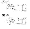
- An applying part 10D according to the modification example 4 of FIG. 13 has the upper-face taper portion 21 having no steps and is integrally formed flat from rearward of the ejection port 24a to the flat portion 25, but the lower-face taper portion 22 is formed in an arc shape with lower ends opened, and the applying part 10 is warped downwardly as a whole from the rear to the front in a side view.
- the ejection port 24a is in an open state at all times.
- the application liquid 4 fed from the ejection port 24a remains including in the rear side and a larger quantity of application liquid than that of the aforementioned modification example 3 is easily held by the upper-face taper portion 21 and is also easily close-contacted and widely spread in a wide range from the base end to the front end of the applying part at the time of application for objective parts.
- the lower-face taper portion 22 is set as being in an arc shape, it is possible to obtain a milder elasticity in the whole of the applying part 10D.
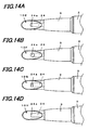
- FIGS. 14(a) to (d) are applying parts 10E to 10H according to the modification examples 5 to 8, which show each example where the ejection port 24a which is opened in the upper-face taper portion 21 is variously changed.
- the ejection port 24a has a semicircular shape and an application liquid is easily fed frontward.
- the ejection port 24a has a circular shape and an application liquid is easily fed frontward and rearward.
- the applying part 10G of the modification example 7 shown in FIG. 14(c) has the ejection portion 24a in a rectangular shape.
- the ejection port 24a is formed with a slit, is opened with a pressure by elastic force of the applying part 10G, and is closed when there is no pressure or pressure is reduced, thus making it possible to prevent that undesirable substances such as external dirt and various germs are mixed in the application liquid 4 in the communication channel 24 and the application liquid reservoir space 2b.
- the communication channel 24 is bent into a "projected V-shape" to the upper-face taper portion 21 in the vicinity of the upper-face taper portion 21, it is also possible to extend the communication channel 24 straightly in an axial direction to form the ejection port 24a.
- FIGS. 15 to 16 are embodiments 2 to 3 in which the liquid pressing mechanism 6 of the liquid applicator of the embodiment is changed. Note that, same reference numerals are given to same parts as those of embodiments in the aforementioned FIGS. 1 to 2 .
- the applying parts 10A to 10H according to the modification examples 1 to 8 shown in FIGS. 10 to 14 can be employed as the applying part 10 of the embodiments 2 to 3.
- an introducing path for an application liquid is opened and closed in the main body 2 for storing the application liquid 4 therein, and the valve-type liquid pressing mechanism (referred to also as the valve device) 6 for pushing out the application liquid toward the applying part 10 is incorporated.
- the valve-type liquid pressing mechanism referred to also as the valve device 6 for pushing out the application liquid toward the applying part 10 is incorporated.
- the main body 2 is provided with an outer barrel 46 in which both of front and rear ends are opened; a liquid introducing pipe 47 which is press fitted into a front end of the outer barrel 46 in a water-tight state; an inner barrel 48 which stores an application liquid, is disposed so as to be movable in an axial direction within the outer barrel 46, and is mated with a rear part of the liquid introducing pipe 47 so as to be slidable in a water-tight state; the liquid pressing mechanism (the valve device) 6 which is incorporated in a front part of the inner barrel 48, and pushes out the application liquid in the inner barrel 48 toward the liquid introducing pipe 47 by opening a valve when the inner barrel 48 is clicked in an axial direction from the side of a rear-end opening 46a of the outer barrel 46; a front barrel 49 which is fitted in the outer side of the liquid introducing pipe 47, and is fixed to an outer periphery of a front-end opening 46b of the outer barrel 46 so as to fasten the liquid introducing pipe 47 in an
- the inner barrel 48 is formed into a cylindrical shape with a bottom, and is made of a tank 48b in which a substantially cylindrical application liquid reservoir space extending rearward from a rear end of a male thread 48a in a front end is formed.
- the predetermined application liquid 4 and an agitation ball 52 for agitating the same are stored.
- the liquid pressing mechanism 6 is provided with a spring receiver 53 which is press fitted into an inner periphery of the male thread 48a in the inner barrel 48, and has a window 53a on a peripheral wall; a valve rod 54 including a piston vane 54a which has a rear end supported slidably in a water-tight state by a rear end of the spring receiver 53, and slidingly contacts with an inner periphery of the spring receiver 53 in the vicinity of a front end of the window 53a; a valve spring 55 which urges the valve rod 54 forward in the spring receiver 53; and a valve seat 56 including a valve port 56a being press fitted into an inner periphery of the spring receiver 53, in which a front end of the valve spring 55 comes into contact therewith so as to be attachable and detachable.
- the spring receiver 53 and the valve seat 56 are fastened in an axial direction by an inner front barrel 57 which is threaded to the male thread 48a of the inner barrel 48, and the inner front barrel 57 and the valve seat 56 are fitted with the outer periphery of the liquid introducing pipe 47 so as to be movable in an axial direction through a ring-shaped sealing part 58 which is sandwiched teherebetween.
- the cap 7 is fit on the front barrel 3 to cover the applying part 10 at a time of nonuse.
- FIG. 16 is a vertical sectional view of the liquid applicator according to the embodiment 3.
- the liquid pressing mechanism 6 is made of a tube part 60
- the tube part 60 is a hollow cylindrical package in which a flexible thin film body which is made of a resinous material or a metallic material is made a single layer or is layered (laminate etc.,), a rear end 60a is closed by welding or adhering, and the applying part 10 is fixed by a front barrel 61 into which a tube part front end 60b which is cylindrically protruded and opened is screwed.
- the inside of the tube part 60 serves as an application liquid reservoir space 60c in which the application liquid 4 is injected and stored from a front end, and by reducing the internal volume of the tube part 60, the application liquid 4 can be pushed out from the front end 60b side.
- the tube part front end 60b is provided with a liquid introducing pipe 62 which is press fitted in a water-tight state; the front barrel 61 which is fitted in the outer side of the liquid introducing pipe 62, and is fixed to an outer periphery of a front-end opening of the tube part front end 60b so as to fasten the liquid introducing pipe 62 in an axial direction; and a pipe 63 in which, in a state where the front end of the applying part 10 is exposed from the front barrel 61, a front end is connected to the communication channel 24 and a rear end is press fitted into the front end of the liquid introducing pipe 62 in a water-tight state, wherein a flange-shaped portion of the rear end in the applying part 10 is fixed by threading the front barrel 61 to the tube part front end 60b by interposing a sealing ring 64.
- the pipe 63 is not always necessary depending on the viscosity of the application liquid and the hardness of the applying part.
- a liquid applicator of the present invention is used as a liquid applicator for applying an application liquid such as cosmetics and a chemical liquid to a soft object such as skin and oral cavity, thus it is possible to provide a liquid applicator having no application unevenness and good application property.
Landscapes
- Coating Apparatus (AREA)
- Containers And Packaging Bodies Having A Special Means To Remove Contents (AREA)
Abstract
Claims (2)
- Applicateur pour liquide (1) comprenant :un corps principal cylindrique (2) ;une partie d'application (10) prévue sur l'extrémité avant dudit corps principal cylindrique ; et un chapeau (7) couvrant au moins ladite partie d'application, dans lequelledit corps principal cylindrique est doté d'un espace réservoir de liquide d'application (2b) pour le stockage d'un liquide d'application (4) présentant une viscosité comprise entre 1 000 (mPs) et 100 000 (mPs), etdes moyens de compression de liquide (6) pour la compression dudit liquide d'application dans le corps principal de sorte à fournir le liquide d'application (4) à la partie d'application (10) prévue sur l'extrémité avant du corps principal en comprimant lesdits moyens de compression de liquide (6), dans lequel la partie d'application (10) est fabriquée en un matériau élastique, formé avec un canal de communication (24) pour la liaison entre l'intérieur du corps principal (2) etl'extérieur, et la portion d'application (10a) de la partie d'application (10) est prévue pour faire saillie encore plus vers l'extrémité avant depuis la partie d'éjection (24a) du canal de communication (24), dans lequel l'extrémité avant de la partie d'application (10) présente une forme plate et effilée, dans lequel ledit orifice d'éjection (24a) est disposé approximativement vers le haut dans un état normalement ouvert dans une partie approximativement centrale de ladite portion d'application plate (10a), dans lequeldans la partie d'application (10), une distance L entre ledit orifice d'éjection (24a) etl'extrémité avant est comprise dans une plage de dimension de 1 < L < 20 (mm), etune largeur W de la partie centrale de la partie d'application (10) est comprise dans une plage de dimension de 2 ≤ W ≤ 20 (mm), et l'extrémité avant de ladite partie d'application (10) lors du pliage par pression du plan vertical au plan horizontal comprenant une force de répulsion dans le sens vertical de 0,01 à 1,40 (N) sur une partie de 3 mm depuis l'extrémité avant, dans lequel la force de répulsion dans le sens vertical est mesurée en amenant une partie de 3 mm depuis l'extrémité avant de la portion d'application en contact avec l'arête de détection (40a) par coulissement depuis une direction latérale, et selon l'état de laquelle la force N que la portion d'application reçoit depuis l'arête de détection (40a), est mesurée.
- Applicateur pour liquide selon la revendication 1, dans lequel la partie d'application est fabriquée en un matériau transparent ou translucide de sorte qu'une encre dans le canal de communication soit visuellement observée.
Applications Claiming Priority (2)
| Application Number | Priority Date | Filing Date | Title |
|---|---|---|---|
| JP2006061190A JP4387365B2 (ja) | 2006-03-07 | 2006-03-07 | 液体塗布具 |
| PCT/JP2007/054236 WO2007102477A1 (fr) | 2006-03-07 | 2007-03-06 | Applicateur pour liquide |
Publications (3)
| Publication Number | Publication Date |
|---|---|
| EP2008545A1 EP2008545A1 (fr) | 2008-12-31 |
| EP2008545A4 EP2008545A4 (fr) | 2010-03-03 |
| EP2008545B1 true EP2008545B1 (fr) | 2012-08-22 |
Family
ID=38474904
Family Applications (1)
| Application Number | Title | Priority Date | Filing Date |
|---|---|---|---|
| EP07737811A Active EP2008545B1 (fr) | 2006-03-07 | 2007-03-06 | Applicateur pour liquide |
Country Status (5)
| Country | Link |
|---|---|
| US (1) | US8282303B2 (fr) |
| EP (1) | EP2008545B1 (fr) |
| JP (1) | JP4387365B2 (fr) |
| CA (1) | CA2644466A1 (fr) |
| WO (1) | WO2007102477A1 (fr) |
Cited By (8)
| Publication number | Priority date | Publication date | Assignee | Title |
|---|---|---|---|---|
| USD753922S1 (en) | 2013-12-16 | 2016-04-19 | Colgate-Palmolive Company | Toothbrush |
| USD760499S1 (en) | 2013-12-16 | 2016-07-05 | Colgate-Palmolive Company | Toothbrush |
| USD764175S1 (en) | 2013-12-16 | 2016-08-23 | Colgate-Palmolive Company | Toothbrush |
| USD764805S1 (en) | 2013-12-16 | 2016-08-30 | Colgate-Palmolive Company | Toothbrush |
| USD765985S1 (en) | 2013-12-16 | 2016-09-13 | Colgate-Palmolive Company | Toothbrush |
| USD765984S1 (en) | 2013-12-16 | 2016-09-13 | Colgate-Palmolive Company | Toothbrush |
| USD765986S1 (en) | 2013-12-16 | 2016-09-13 | Colgate-Palmolive Company | Toothbrush |
| USD765983S1 (en) | 2013-12-16 | 2016-09-13 | Colgate-Palmolive Company | Toothbrush |
Families Citing this family (9)
| Publication number | Priority date | Publication date | Assignee | Title |
|---|---|---|---|---|
| JP5288934B2 (ja) * | 2008-08-08 | 2013-09-11 | 三菱鉛筆株式会社 | 液体塗布具 |
| JP5305815B2 (ja) * | 2008-09-30 | 2013-10-02 | 株式会社 資生堂 | 粘性化粧料用容器 |
| JP5858640B2 (ja) * | 2011-04-28 | 2016-02-10 | 三菱鉛筆株式会社 | 塗布具 |
| JP6016420B2 (ja) * | 2011-04-28 | 2016-10-26 | 三菱鉛筆株式会社 | 塗布具 |
| US9339452B2 (en) | 2012-06-22 | 2016-05-17 | Mitsubishi Pencil Company, Limited | High internal water phase water-in-oil emulsified cosmetic and cosmetic liquid applicator |
| SE537984C2 (sv) * | 2014-02-07 | 2016-01-12 | Cloz Man Ab | Applikator för applicering av en produkt på huvudhår och färgningskit innefattande nämnda applikator |
| JP6424019B2 (ja) * | 2014-06-09 | 2018-11-14 | 株式会社 マリーヌ | 液体塗布具 |
| KR102053019B1 (ko) * | 2018-01-31 | 2019-12-09 | 주식회사 라인프러스 | 펜 형 화장품 용기 |
| DE102018120515A1 (de) * | 2018-08-22 | 2020-02-27 | Viktor Herzog | Vorrichtung und Verfahren zum Speichern und dosierten Auftragen einer Flüssigkeit auf eine Oberfläche |
Family Cites Families (15)
| Publication number | Priority date | Publication date | Assignee | Title |
|---|---|---|---|---|
| US2442503A (en) * | 1946-02-27 | 1948-06-01 | Melnikoff Zachary | Lip rouge applicator |
| US3825021A (en) * | 1973-05-07 | 1974-07-23 | Applicator Brush Co Inc | Cosmetic applicator |
| JPS6167621U (fr) | 1984-10-11 | 1986-05-09 | ||
| JPH0632221Y2 (ja) | 1986-08-30 | 1994-08-24 | ぺんてる株式会社 | 塗布具 |
| JP3109917B2 (ja) | 1992-09-07 | 2000-11-20 | 学校法人東海大学 | 原子炉の崩壊熱除去システム |
| JP2603088Y2 (ja) | 1993-04-23 | 2000-02-14 | 三菱鉛筆株式会社 | 流動体の塗布部材 |
| JP3081834B2 (ja) | 1998-03-20 | 2000-08-28 | 三菱鉛筆株式会社 | 液体塗布具 |
| JP4726279B2 (ja) | 2000-06-30 | 2011-07-20 | 三菱鉛筆株式会社 | 液体塗布具 |
| JP2002067568A (ja) | 2000-08-31 | 2002-03-08 | Pentel Corp | 筆記具用部品 |
| US7201527B2 (en) * | 2004-07-30 | 2007-04-10 | Hct Limited | Twist up pen type dispenser with brush applicator |
| JP2006123305A (ja) | 2004-10-28 | 2006-05-18 | Pentel Corp | 塗布具 |
| US7857538B2 (en) | 2004-11-10 | 2010-12-28 | Tokiwa Corporation | Filler extruding container for coating |
| JP3769585B1 (ja) | 2004-11-10 | 2006-04-26 | 株式会社資生堂 | 塗布用充填物押出容器 |
| JP3796258B2 (ja) * | 2004-11-10 | 2006-07-12 | 株式会社トキワ | 液状充填物押出容器 |
| JP3109917U (ja) | 2005-01-20 | 2005-06-02 | 洽興塑膠廠股▲ふん▼有限公司 | 液体化粧料塗布具の構造 |
-
2006
- 2006-03-07 JP JP2006061190A patent/JP4387365B2/ja active Active
-
2007
- 2007-03-06 EP EP07737811A patent/EP2008545B1/fr active Active
- 2007-03-06 US US12/280,711 patent/US8282303B2/en active Active
- 2007-03-06 CA CA002644466A patent/CA2644466A1/fr not_active Abandoned
- 2007-03-06 WO PCT/JP2007/054236 patent/WO2007102477A1/fr active Application Filing
Cited By (8)
| Publication number | Priority date | Publication date | Assignee | Title |
|---|---|---|---|---|
| USD753922S1 (en) | 2013-12-16 | 2016-04-19 | Colgate-Palmolive Company | Toothbrush |
| USD760499S1 (en) | 2013-12-16 | 2016-07-05 | Colgate-Palmolive Company | Toothbrush |
| USD764175S1 (en) | 2013-12-16 | 2016-08-23 | Colgate-Palmolive Company | Toothbrush |
| USD764805S1 (en) | 2013-12-16 | 2016-08-30 | Colgate-Palmolive Company | Toothbrush |
| USD765985S1 (en) | 2013-12-16 | 2016-09-13 | Colgate-Palmolive Company | Toothbrush |
| USD765984S1 (en) | 2013-12-16 | 2016-09-13 | Colgate-Palmolive Company | Toothbrush |
| USD765986S1 (en) | 2013-12-16 | 2016-09-13 | Colgate-Palmolive Company | Toothbrush |
| USD765983S1 (en) | 2013-12-16 | 2016-09-13 | Colgate-Palmolive Company | Toothbrush |
Also Published As
| Publication number | Publication date |
|---|---|
| WO2007102477A1 (fr) | 2007-09-13 |
| EP2008545A1 (fr) | 2008-12-31 |
| EP2008545A4 (fr) | 2010-03-03 |
| JP4387365B2 (ja) | 2009-12-16 |
| US8282303B2 (en) | 2012-10-09 |
| JP2007236529A (ja) | 2007-09-20 |
| US20100232866A1 (en) | 2010-09-16 |
| CA2644466A1 (fr) | 2007-09-13 |
Similar Documents
| Publication | Publication Date | Title |
|---|---|---|
| EP2008545B1 (fr) | Applicateur pour liquide | |
| US8011847B2 (en) | Extruding container of applying filler | |
| JPH09322819A (ja) | 塗布具 | |
| US4624594A (en) | Fluid dispenser | |
| EP1396210B1 (fr) | Récipient pour un liquide | |
| EP2319358B1 (fr) | Outil d'application de liquide | |
| EP2566630B1 (fr) | Dispositif applicateur de liquide | |
| JP4551914B2 (ja) | 液体塗布具 | |
| WO2006049283A1 (fr) | Applicateur de liquide | |
| JP2007130157A (ja) | 液体塗布具 | |
| WO2007055277A1 (fr) | Applicateur de liquide | |
| JP4607746B2 (ja) | 内容物押出容器 | |
| JP2015042215A (ja) | 化粧料容器 | |
| JP2007236961A (ja) | 液体塗布具 | |
| CN107028328B (zh) | 液状化妆品容器 | |
| JP4028880B2 (ja) | 塗布用充填物押出容器 | |
| JP3991059B2 (ja) | 塗布用充填物押出容器 | |
| JP3149895U (ja) | 液体塗布具 | |
| US9603436B2 (en) | Applicator | |
| JP5164485B2 (ja) | 液体化粧料塗布具 | |
| JP4711995B2 (ja) | 液体塗布具 | |
| JP2007236960A (ja) | 液体塗布具 | |
| JP5037197B2 (ja) | 液体塗布具 | |
| JP4579653B2 (ja) | 塗布用充填物押出容器 | |
| JP2003312185A (ja) | 塗布具 |
Legal Events
| Date | Code | Title | Description |
|---|---|---|---|
| PUAI | Public reference made under article 153(3) epc to a published international application that has entered the european phase |
Free format text: ORIGINAL CODE: 0009012 |
|
| 17P | Request for examination filed |
Effective date: 20080904 |
|
| AK | Designated contracting states |
Kind code of ref document: A1 Designated state(s): AT BE BG CH CY CZ DE DK EE ES FI FR GB GR HU IE IS IT LI LT LU LV MC MT NL PL PT RO SE SI SK TR |
|
| AX | Request for extension of the european patent |
Extension state: AL BA HR MK RS |
|
| DAX | Request for extension of the european patent (deleted) | ||
| RBV | Designated contracting states (corrected) |
Designated state(s): FR |
|
| REG | Reference to a national code |
Ref country code: DE Ref legal event code: 8566 |
|
| A4 | Supplementary search report drawn up and despatched |
Effective date: 20100203 |
|
| 17Q | First examination report despatched |
Effective date: 20101117 |
|
| GRAP | Despatch of communication of intention to grant a patent |
Free format text: ORIGINAL CODE: EPIDOSNIGR1 |
|
| RIC1 | Information provided on ipc code assigned before grant |
Ipc: A45D 34/04 20060101AFI20111229BHEP |
|
| GRAS | Grant fee paid |
Free format text: ORIGINAL CODE: EPIDOSNIGR3 |
|
| GRAA | (expected) grant |
Free format text: ORIGINAL CODE: 0009210 |
|
| AK | Designated contracting states |
Kind code of ref document: B1 Designated state(s): FR |
|
| PLBE | No opposition filed within time limit |
Free format text: ORIGINAL CODE: 0009261 |
|
| STAA | Information on the status of an ep patent application or granted ep patent |
Free format text: STATUS: NO OPPOSITION FILED WITHIN TIME LIMIT |
|
| 26N | No opposition filed |
Effective date: 20130523 |
|
| REG | Reference to a national code |
Ref country code: FR Ref legal event code: PLFP Year of fee payment: 9 |
|
| REG | Reference to a national code |
Ref country code: FR Ref legal event code: PLFP Year of fee payment: 10 |
|
| REG | Reference to a national code |
Ref country code: FR Ref legal event code: PLFP Year of fee payment: 11 |
|
| REG | Reference to a national code |
Ref country code: FR Ref legal event code: PLFP Year of fee payment: 12 |
|
| PGFP | Annual fee paid to national office [announced via postgrant information from national office to epo] |
Ref country code: FR Payment date: 20230208 Year of fee payment: 17 |
|
| P01 | Opt-out of the competence of the unified patent court (upc) registered |
Effective date: 20230419 |