EP2006544A2 - Pompe à pistons avec excentricité variable - Google Patents
Pompe à pistons avec excentricité variable Download PDFInfo
- Publication number
- EP2006544A2 EP2006544A2 EP20080005400 EP08005400A EP2006544A2 EP 2006544 A2 EP2006544 A2 EP 2006544A2 EP 20080005400 EP20080005400 EP 20080005400 EP 08005400 A EP08005400 A EP 08005400A EP 2006544 A2 EP2006544 A2 EP 2006544A2
- Authority
- EP
- European Patent Office
- Prior art keywords
- eccentric
- pump
- elements
- sleeve
- main axis
- Prior art date
- Legal status (The legal status is an assumption and is not a legal conclusion. Google has not performed a legal analysis and makes no representation as to the accuracy of the status listed.)
- Granted
Links
Images


Classifications
-
- F—MECHANICAL ENGINEERING; LIGHTING; HEATING; WEAPONS; BLASTING
- F04—POSITIVE - DISPLACEMENT MACHINES FOR LIQUIDS; PUMPS FOR LIQUIDS OR ELASTIC FLUIDS
- F04B—POSITIVE-DISPLACEMENT MACHINES FOR LIQUIDS; PUMPS
- F04B49/00—Control, e.g. of pump delivery, or pump pressure of, or safety measures for, machines, pumps, or pumping installations, not otherwise provided for, or of interest apart from, groups F04B1/00 - F04B47/00
- F04B49/12—Control, e.g. of pump delivery, or pump pressure of, or safety measures for, machines, pumps, or pumping installations, not otherwise provided for, or of interest apart from, groups F04B1/00 - F04B47/00 by varying the length of stroke of the working members
- F04B49/123—Control, e.g. of pump delivery, or pump pressure of, or safety measures for, machines, pumps, or pumping installations, not otherwise provided for, or of interest apart from, groups F04B1/00 - F04B47/00 by varying the length of stroke of the working members by changing the eccentricity of one element relative to another element
- F04B49/125—Control, e.g. of pump delivery, or pump pressure of, or safety measures for, machines, pumps, or pumping installations, not otherwise provided for, or of interest apart from, groups F04B1/00 - F04B47/00 by varying the length of stroke of the working members by changing the eccentricity of one element relative to another element by changing the eccentricity of the actuation means, e.g. cams or cranks, relative to the driving means, e.g. driving shafts
-
- F—MECHANICAL ENGINEERING; LIGHTING; HEATING; WEAPONS; BLASTING
- F04—POSITIVE - DISPLACEMENT MACHINES FOR LIQUIDS; PUMPS FOR LIQUIDS OR ELASTIC FLUIDS
- F04B—POSITIVE-DISPLACEMENT MACHINES FOR LIQUIDS; PUMPS
- F04B1/00—Multi-cylinder machines or pumps characterised by number or arrangement of cylinders
- F04B1/04—Multi-cylinder machines or pumps characterised by number or arrangement of cylinders having cylinders in star- or fan-arrangement
- F04B1/06—Control
- F04B1/07—Control by varying the relative eccentricity between two members, e.g. a cam and a drive shaft
-
- Y—GENERAL TAGGING OF NEW TECHNOLOGICAL DEVELOPMENTS; GENERAL TAGGING OF CROSS-SECTIONAL TECHNOLOGIES SPANNING OVER SEVERAL SECTIONS OF THE IPC; TECHNICAL SUBJECTS COVERED BY FORMER USPC CROSS-REFERENCE ART COLLECTIONS [XRACs] AND DIGESTS
- Y10—TECHNICAL SUBJECTS COVERED BY FORMER USPC
- Y10T—TECHNICAL SUBJECTS COVERED BY FORMER US CLASSIFICATION
- Y10T83/00—Cutting
- Y10T83/869—Means to drive or to guide tool
Definitions
- the invention relates to an eccentric pump, as described in the preamble of claim 1.
- Displacement pumps in particular radial piston pumps are already known from the prior art, in which the delivery volume can be actively influenced by an adjustable eccentricity of an eccentric element of the radial piston pump.
- a radial piston pump is known in which the variable eccentricity is effected by an adjustable adjusting element in the axial direction in the form of an inclined cylinder body.
- the forces exerted by the radial piston on the adjusting element or its axial portion are compensated by an axially acting on the adjusting spring element and thereby arises depending on the system pressure acting on the pump elements a certain axial displacement of the adjusting against the force of Spring elements.
- a lower eccentricity of the adjusting element and thereby a reduced delivery volume of the radial piston pump is effected with increasing system pressure and thereby caused greater axial displacement of the adjusting element. Since the required drive power of such a pump is proportional to the product of delivery volume and system pressure, the drive power and thus the load of a drive motor remains largely constant at different system pressures by such an arrangement and the drive motor can be designed for lower or largely constant loads, thereby the production of such a radial piston pump becomes more economical.
- the object of the invention is to provide a positive displacement pump, which has largely constant power requirement with variable system pressures, so to speak is self-regulating and yet can be equipped with simple running, inexpensive pumping elements, without being over-stressed.
- the object of the invention is achieved by the features of the characterizing part of claim 1, according to which the eccentric sleeve bearing pump shaft portion is formed as an oblique eccentric pin with a main axis of the pump shaft extending in a helix angle eccentric pin axis and guided on the eccentric eccentric sleeve has a cylindrical outer surface whose Generating parallel to the main axis.
- Due to the oblique eccentric pin is the variable eccentricity of the eccentric sleeve, and thus causes the variable delivery volume of the pump elements; through the cylindrical surface, whose generatrices extend parallel to the main axis of the pump shaft, axial force components are exerted on the eccentric sleeve at the contact point between the pump piston and the lateral surface with respect to the eccentric sleeve only in the form of frictional forces during an axial displacement of the eccentric sleeve on the eccentric pin.
- the transverse forces acting on the pump piston are thereby substantially lower than in the prior art and largely negligible, whereby simply constructed and thus inexpensive pump elements can be used in such a positive displacement pump, without these being subject to excessive stresses and thereby caused wear.
- the helix angle of the eccentric pin acts on the rotating with the driven pump shaft eccentric sleeve in addition to the force exerted by the spring force and a centrifugal force that wants to drive the eccentric sleeve in the direction of greater eccentricity and therefore supports the spring force. Only in the position in which the center of gravity of the eccentric sleeve comes to lie exactly in the main axis of the pump shaft, the centrifugal force and caused by this force component disappears in the direction of increasing eccentricity.
- such an eccentric pump can therefore adjust the delivery volume automatically and in dependence adjust automatically from the applied system pressure, whereby a largely constant level of performance of the pump drive is given.
- the relative position of the eccentric pin axis with respect to the main axis of the pump shaft can also be skewed when cooperating with the eccentric hole in the eccentric sleeve extends so that the generatrix of the outer surface of the eccentric sleeve parallel to the main axis of the pump shaft.
- eccentric pin axis intersects the main axis. Furthermore, even if a central axis of the lateral surface intersects the eccentric pin axis. As a result, simple geometrical relationships are achieved and the influences of the geometry on the dynamic behavior during operation can be estimated more easily.
- the eccentric pin can have any cross-section which is constant over its length, it is advantageous and simpler for manufacture if the lateral surface of the eccentric pin is designed as a circular cylinder surface with the eccentric pin axis as a circular cylinder axis.
- the spring element acting axially on the eccentric sleeve on the pump shaft section is advantageously formed by a compression spring or tension spring which is supported on the pump shaft.
- Such spring elements are readily available in a wide range and can thus be easily adapted by the choice of the spring rate of the spring element, the dynamic behavior of the eccentric sleeve. It is possible that a spring element is provided which surrounds the eccentric pin concentric, and is guided on this; It is also possible that a plurality of spring elements are provided which engage distributed on the eccentric sleeve on a pitch circle outside of the eccentric pin.
- the axial displaceability of the eccentric sleeve on the eccentric pin is limited at least in one direction by a stop element and thus a starting position or starting position is defined.
- a travel limit of the eccentric sleeve on the eccentric pin can be done for example by the shape of the pump shaft, ie in which the pump shaft itself forms a stop element.
- the adjustment can be limited by a pump housing, further, the adjustment can also be adjustable, in which the stop element is designed in the form of a set screw.
- An advantageous operating behavior of the eccentric pump is achieved when the eccentric sleeve is biased in the starting position at low pressure level in the pump elements by the spring element against the stop element.
- the starting position at low back pressure can be predetermined by the initial position eccentricity and thus a certain delivery volume of the eccentric pump, for example, for idling operation of the eccentric pump when the consumer side there is no increased pressure requirement.
- the starting position can be assigned both a maximum delivery volume and a minimum delivery volume, which depends on the purpose of the eccentric pump.
- the delivery volume at idle at low pressure level in the pumping elements is maximum and regulates as described above with increasing system pressure in the direction of smaller displacement, whereby the drive power of the eccentric pump remains largely constant.
- the eccentric sleeve has a minimal eccentricity in the starting position, and the movement of the eccentric sleeve in the direction of increasing eccentricity is effected by the centrifugal force acting on the eccentric sleeve.
- the spring rate of the spring element is selected so that upon displacement of the eccentric sleeve from the initial position, the increase in the spring force exerted by the spring force is greater than the decrease in the axial component, acting on the eccentric centrifugal force, a stable operating behavior of the eccentric pump is ensured and it can be prevented at an occurring consumer-side pressure increase, that the delivery volume of the eccentric pump is lowered too much.
- a helix angle between the main axis and the eccentric pin axis has proven to be from a range with a lower limit of 3 ° and an upper limit of 20 °. At a helix angle of 10 ° results in an advantageous response of the eccentric pump at the consumer side Pressure fluctuations and at the same time a compact size of the eccentric pump.
- the eccentric pin can be mounted in an easy-mounting manner at one end of the pump shaft. This makes it possible that both the eccentric sleeve and the pump shaft with the eccentric pin can each be made in one piece and do not have to be composed.
- eccentric pin is arranged on a circular-cylindrical crank arm of the crankshaft, in particular on a concentric crank axis to the main axis, provides the end face of the circular cylindrical crank arm sufficient surface for supporting the spring elements and for attaching stop elements to limit the axial adjustment of the eccentric sleeve. Furthermore, such a crank arm forms a relatively large flywheel, which is advantageous for the synchronization of such eccentric pump.
- the eccentric sleeve has a cylindrical roller bearing whose outer ring forms the lateral surface.
- the outer ring of the rolling bearing has a width which is greater than the axial displacement of the eccentric sleeve. Since only very low frictional forces are effective in the axial direction, needle bearings can also be readily installed.
- the eccentric pump can also be designed so that along the pump shaft a plurality of eccentric, in particular rotationally symmetrical with respect to the main axis are arranged and each eccentric pin own group of pump elements, in particular a fixed, several pump elements comprehensive cylinder star is assigned.
- the pressure lines of the pump elements in each case one cylinder star are combined in each case to a common high pressure port which is used to supply a consumer.
- Due to the multiple eccentric and cylinder stars are several separate high-pressure connections for multiple consumers available, with the delivery volumes of the individual cylinder stars can each independently adapt to the operating condition of the respective consumer.
- a common drive motor for several consumers is also claimed very evenly.
- the eccentric pump can also be designed so that at least two pump shafts are arranged on the frame at least one eccentric, each associated with its own group of pump elements, parallel to each other and are driven by a common drive device. Between the at least two parallel pump shafts, a drive connection can be produced by simple means, for example a traction mechanism, in particular a toothed belt drive, and only one drive motor is required, which is subjected to very uniform stress due to the pump characteristic.
- the frame is designed as a housing and the pump elements are arranged in the housing containing a lubricant reservoir, and the pump shaft passes through the housing sealed.
- the lubricant can be introduced by the movements of the pump shaft to the wear-prone contact points and in particular at the same time form the pressure medium to be pumped by the pump elements.
- the pump elements can therefore suck directly from the pressure medium supply, which is also lubricant supply, within the housing.
- the pump elements of the eccentric pump advantageously have spring elements, which are the displacement elements biasing radially in the direction of the main axis against the lateral surface of the eccentric sleeve.
- the displacement elements in the form of piston elements or membrane elements can thereby perform the suction of pressure medium in the displacements of the pump elements automatically, without that tensile forces must be exerted by the eccentric sleeve on the displacement elements. This results in a simple construction of the eccentric pump.
- suction valves in particular plate seat valves
- suction valves are arranged between the displacements in the pump elements and a pressure medium supply.
- suction valves in particular plate seat valves, which during the intake stroke, a backflow of pressure medium from the high pressure side is prevented in the displacements.
- control of the pump elements i. the pressure medium inlet or the pressure medium discharge into or out of the displacements of the pump elements by means of a slide control, which may be useful at lower operating speeds of an eccentric pump.
- an eccentric pump In order to achieve the highest operating pressures of such an eccentric pump, it can be designed in particular in the form of a radial piston pump, in which the displacement elements are designed as pump pistons guided in pump cylinders. With such a design operating pressures of over 500 bar, for example, 700 bar, can be easily generated.
- the invention further relates to a recovery device comprising a hydraulic system and a mountain scissors or a mountain spreader driven by the latter, characterized in that the hydraulic system comprises an eccentric pump according to the invention.
- Hydraulic consumers such as Bergescheren or Bergespreizer, are characterized by the fact that they require on the one hand with unloaded tools fast movements and thus large volume flows, but on the other hand require very high operating pressures from the intervention of the tools, in which a fast tool movement and thus high volume flows Not more are needed.
- the drive motor for the eccentric pump can be optimally utilized in all working states, and thus a more cost-effective drive motor can be used.
- the invention further relates to a method for driving a fluid-operated motor, such as a hydraulic cylinder or a hydraulic motor, by means of a pressure medium flow, which is characterized in that the pressure medium flow is provided by an eccentric pump according to the invention. Due to the self-regulating operation of the eccentric pump whose drive motor is in all operating conditions in each case in the range of the optimal operating point and optimum performance.
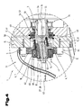
- FIG. 1 and 2 is exemplified the structure and operation of an inventive eccentric pump 1 in the form of external radial piston pump 2 shown.
- This essentially comprises a pump shaft 3, which can also be referred to as eccentric shaft 4.
- This acts in a rotation on peripheral to the eccentric shaft 4 arranged pump elements 5, 5 ', in the displacement elements 6, 6', in the form of pump piston 7, 7 ', displacements 8, 8', periodically reduce and enlarge.
- pressure fluid or hydraulic fluid via a suction line 9, 9 'sucked by a pressure medium supply 10 by increasing the displacement 8 and delivered by reducing the displacement 8 via a pressure line 11 to a high-pressure port 12; from a consumer, such.
- a fluid operating engine in the form of a hydraulic cylinder; a hydraulic motor or the like is supplied.
- the suction valves 13 and the pressure valves 14 may for example be designed as a disk seat valves or else be formed by other valve types.
- the pump shaft 3 and the pump elements 5; 5 ' are stationary with respect to a frame 15 mounted, which is formed for example as a housing.
- the term frame 15 is not related to the type in this context; but on the kinematic function as a reference system, relative to which the pump shaft 3 and displacement elements 6; 6 'of the pump elements 5; 5 'move.
- the pump shaft 3 is of an in Fig. 1 Driven drive device, not shown, and executes a rotation about a main axis 16 during operation.
- the periodic actuation of the displacement elements 6; 6 ' takes place by an eccentric sleeve 17; whose lateral surface 18 eccentrically rotates about the main axis 16.
- the lateral surface 18 of the eccentric sleeve 17 has in the illustrated embodiment, the shape of a circular cylindrical surface 19, whose generatrix 20 are parallel to the main axis 16, whereby a central axis 21 of the circular cylindrical surface 19 extends parallel to the main axis 16.
- the distance between the central axis 21 and the main axis 16 results in an eccentricity 22 of the eccentric sleeve 17 with respect to the main axis 16 and also corresponds to half the stroke of the displacement elements. 6
- the eccentricity 22 is variable, for which the eccentric sleeve 17 is mounted axially displaceably on a pump shaft portion 23 which is formed as an eccentric pin 24 whose eccentric pin axis 25 has a helix angle 26 with respect to the main axis 16.
- This helix angle 26 is in the illustrated embodiment about 10 ° C, but may be preferably selected from a range with a lower limit of 3 ° C and an upper limit of 20 ° C.
- helix angle 26 causes an axial displacement of the eccentric sleeve 17 on the eccentric pin 24, a change in the eccentricity 22, ie, the distance between the central axis 21 of the lateral surface 18 and the major axis 16 is changed by the axial Displacement of the eccentric sleeve 17.
- a rotation 27, in the illustrated embodiment in the form of a feather key 28 is formed.
- any type of anti-rotation 27 may be formed, which allows the axial movement of the eccentric sleeve 17 along the eccentric pin 24, for example a deviating from the circular cross-sectional area 29 of the eccentric 24 and a rotatably cooperating recess or bore 30 in the eccentric sleeve 17th
- the cross section of the eccentric pin 24 For this purpose, it can be designed, for example, as a splined shaft profile or as a polygonal profile.
- the eccentric pin 24 is formed as a circular cylindrical portion 31, the circular cylinder axis 32 forms the eccentric pin axis 25.
- the eccentric pin 24 may also have angular, for example, square cross-section.
- the lateral surface 18 of the eccentric sleeve 17 may alternatively have a deviating from the circular cross-section of the illustrated embodiment, for example, be oval or have flats, the cross-sectional shape to achieve a desired characteristic of the eccentric pump 1 can be used.
- the displacement elements 6 in the form of pump piston 7 are guided in pump cylinders 33 and are pressed by piston springs 34 against the lateral surface 18 of the eccentric sleeve 17 or at least in the direction of the main axis 16.
- the piston springs 34 are chosen so that the intake stroke of the pump elements 5 is performed automatically by the displacement elements 6.
- membrane elements can also be used as displacement elements 6, 6 '.
- the displacement elements 6 can perform the suction stroke by pulling forces when an articulated, suitable for transmitting tensile forces connection between displacement elements 6 and eccentric sleeve 17 is provided.
- the eccentric sleeve 17 may be provided with an outer sleeve, which executes only the translational eccentric movement but not the rotational movement.
- the axial displacement of the eccentric sleeve 17 on the eccentric pin 24 is in Fig. 1 bounded on the left side by a first stop element 35 and to the right by a second stop element 36, wherein as a stop element 35, 36 each have a screw member 37 is inserted, which is used on the crank webs 38 of the pump shaft 3.
- the crank webs 38 have in the illustrated embodiment, the shape of disc-shaped circular cylinder sections.
- a spring element 39 is arranged in the form of a compression spring 40, which on the eccentric sleeve 17th exerts a spring force in the axial direction.
- the spring element 39 may be oriented as shown approximately parallel to the eccentric pin axis 25, but may for example be oriented parallel to the main axis 16 or in any other direction, as long as the spring force can exert a force component parallel to the direction of the eccentric pin axis 25 on the eccentric sleeve 17.
- the spring element 39 is formed in the illustrated embodiment as a compression spring 40, the spring force acts on the eccentric sleeve 17 to the left and the eccentric sleeve 17, when the forces exerted by the pump piston 7 forces are low, pressed to the left against the first stop member 35, whereby a Home position or home position is defined.
- Fig. 3a shows the detail of an eccentric pump 1 according to the invention, in which the eccentric sleeve 17 is pressed by means of the spring element 39 in the form of the compression spring 40 against the left stop element 35 and thereby assumes a starting position 41.
- the eccentricity 22 between the central axis 21 of the eccentric sleeve 17 and the main axis 16 of the pump shaft 3 corresponds to a maximum eccentricity 42, wherein the maximum stroke of the displacement elements 6, 6 'in the form of the pump piston 7, 7' and thereby the maximum Delivery volume of the eccentric pump 1 is given.
- An increase in the system pressure at the high pressure ports 12 thus causes a displacement of the eccentric sleeve 17 in the direction of lower eccentricity 22 in the illustrated embodiment to the right and in turn causes a reduction of the system pressure 12 at the high pressure ports 12 a displacement of the eccentric sleeve 17 in the direction of increasing eccentricity ie in Theoretically, an infinitely increasing pressure at the high pressure ports 12 due to the ever increasing piston force 43 would cause a displacement of the eccentric sleeve 17 so far to the right until the eccentricity 22 disappears and the flow of the Eccentric pump 1 goes to zero. Since such an operating state is undesirable in practice, the displacement of the eccentric sleeve on the eccentric pin 24 is limited by a second stop member 36 to the right.
- FIG. 3b an operating state of an eccentric pump 1 is shown, in which the eccentric sleeve 17 just occupies the end position 48 of its maximum displacement along the eccentric pin 24 and comes into contact with the right, second stop element 36.
- this operating state act on the eccentric sleeve 17 in turn, the resulting piston force 43, which is substantially higher in this operating condition, as in the initial state 41;
- the correspondingly larger contact force 44 between the eccentric pin 24 and the bore 30 in the eccentric sleeve 17 Further reduced by the reduced eccentricity 22 centrifugal force 46 and the increased spring force 47, which just balances the axial components of the piston force 43 and the centrifugal force 47.
- the interaction of the forces is in turn simplified in a separate force polygon.
- the eccentricity 22 between the central axis 21 of the lateral surface 18 of the eccentric sleeve 17 and the main axis 16 of the pump shaft 3 corresponds to a minimum eccentricity 49, which also determines the minimum delivery volume per revolution of the eccentric pump 1.
- Such eccentric pump 1 can thus be influenced in many areas, for example by the choice of the helix angle 26, the position and size of the adjustment of the eccentric 17 on the eccentric 24, the spring characteristic and bias of the spring element 39, the maximum eccentricity 42 and minimal eccentricity 49.
- Fig. 4 shows a detail of a section through a further embodiment of an eccentric pump 1 according to the invention, in which the frame 15 is formed as a housing 50, the pump shaft 3 is guided in the housing interior 51 and at one end 52 of the pump shaft 3, the eccentric sleeve 17 axially displaceable on the end 52 of the pump shaft forming, flying eccentric pin 24 is mounted axially displaceable.
- Fig. 4 shows the eccentric sleeve 17 in the starting position 41, in which this is biased by a plurality of compression springs 40 against an end 52 of the eccentric pin 24 fixed end plate 53.
- the outside of the housing 50 lying part of the pump shaft 3 has a shaft bore 54 with a keyway 55, whereby the pump shaft can be easily connected to a drive motor, not shown.
- the pump shaft 3 is mounted by means of rolling bearings 56 in the form of radial ball bearings 57 in the housing 50 and the housing interior 51 sealed by shaft seals 58 from the environment.
- a plurality of pump elements 6 are fixed on a pitch circle relative to the main axis 16 of the pump shaft 3, which have radially displaceable displacement elements 6 in the form of pump piston 7.
- the operation of the pump elements 5 has already been based on Fig. 1 described and will not be repeated at this point.
- the eccentric sleeve 17 has a cylindrical roller bearing 59 whose outer ring 60 forms the lateral surface 18 of the eccentric sleeve.
- this rotatable roller bearing of the outer ring 60 of this does not perform as the eccentric sleeve 17 is an eccentric rotation with respect to the main axis 16 but performs when the rolling friction between Outer ring and inner ring is neglected a circular translation with respect to the main axis 16, wherein the diameter of this circular motion is twice the eccentricity 22.
- the anti-rotation 27 between the eccentric sleeve 17 and the eccentric pin 24 is again formed by a keyway 28.
- the suction line 9 for a pump element 5 arranged above the liquid level comprises a suction tube 62 which is guided below the liquid level 63.
- the functioning of in Fig. 4 shown eccentric 1 corresponds to the basis of the Fig. 3a and Fig. 3b described operation and will not be described in detail to avoid repetition.
- the pump elements 5 may be arranged on a pitch circle with respect to the main axis 16 and in order to achieve the lowest possible pressure fluctuations at the high pressure port 12, merged into a common port and distributed uniformly over the circumference of the pitch circle.
- 4 to 9 pump elements 5 may be assigned to an eccentric sleeve 17 and form a so-called cylinder star 64 by their star-shaped arrangement.
- Fig. 5 shows as an example of the use of an eccentric pump 1 according to the invention a recovery device 65, comprising a Bergeschere 66 or a Bergespreizer and a hydraulic system 67 with the eccentric pump 1 according to the invention and a hydraulic control 68 for controlling the flow of fluid to or from the Bergeschere 66.
- the Bergeschere 66 includes a fluid operated motor 69 in the form of a hydraulic cylinder 70 which converts the flow of hydraulic fluid into movements of the recovery tools.
- the provision of the pressure medium flow is effected by an eccentric pump 1, in which the pump shaft 3 has a plurality of, in the illustrated embodiment, three eccentric pins 24, each of which a plurality of pump elements 5 comprehensive cylinder star 64 is assigned.
- the pressure lines 11 of the pump elements 5 each of a cylinder star 64 are combined to form a common high-pressure port 12.
- the three cylinder stars 64 thus provide three high-pressure connections, one of which is connected to the consumer in the form of the mountain shear 66 by the hydraulic control 68 and two additional high-pressure connections 12 ', 12 "are available for additional consumers 5 are connected by suction pipes 62 to the pressure medium supply 71 contained in the housing 50.
- the hydraulic system comprises a pressure limiting valve 72.
- the drive of the pump shaft 3 is effected by a drive device 73, which is indicated only symbolically, for example in the form of a the electric motor.
- Fig. 4 is still shown the possibility of driving by means of a drive device 73 driven pump shaft 3 by means of a toothed belt drive 74 one or more further pump shafts, not shown, whereby a plurality of eccentric pump units can be operated with only one drive motor and separate consumers for several hydraulic circuits are available.
Applications Claiming Priority (1)
| Application Number | Priority Date | Filing Date | Title |
|---|---|---|---|
| AT0093707A AT505439B1 (de) | 2007-06-18 | 2007-06-18 | Exzenterpumpe |
Publications (3)
| Publication Number | Publication Date |
|---|---|
| EP2006544A2 true EP2006544A2 (fr) | 2008-12-24 |
| EP2006544A3 EP2006544A3 (fr) | 2009-02-18 |
| EP2006544B1 EP2006544B1 (fr) | 2011-01-12 |
Family
ID=39381876
Family Applications (1)
| Application Number | Title | Priority Date | Filing Date |
|---|---|---|---|
| EP20080005400 Expired - Fee Related EP2006544B1 (fr) | 2007-06-18 | 2008-03-22 | Pompe à pistons avec excentricité variable |
Country Status (5)
| Country | Link |
|---|---|
| US (1) | US8322997B2 (fr) |
| EP (1) | EP2006544B1 (fr) |
| AT (2) | AT505439B1 (fr) |
| DE (1) | DE502008002260D1 (fr) |
| WO (1) | WO2008154665A2 (fr) |
Cited By (3)
| Publication number | Priority date | Publication date | Assignee | Title |
|---|---|---|---|---|
| EP2584197A1 (fr) | 2011-10-21 | 2013-04-24 | Hydr'am | Pompe hydraulique radiale a excentricite et debit variables |
| CN104895754A (zh) * | 2015-04-07 | 2015-09-09 | 西安交通大学 | 一种轴向柱塞与径向柱塞复合的液压泵 |
| CN110945242A (zh) * | 2017-08-22 | 2020-03-31 | 罗伯特·博世有限公司 | 用于液压的助力-车辆制动设备的活塞泵总成 |
Families Citing this family (6)
| Publication number | Priority date | Publication date | Assignee | Title |
|---|---|---|---|---|
| US9003955B1 (en) | 2014-01-24 | 2015-04-14 | Omax Corporation | Pump systems and associated methods for use with waterjet systems and other high pressure fluid systems |
| DE102017206723A1 (de) | 2017-04-21 | 2018-10-25 | Mando Corporation | Kolbenpumpenanordnung umfassend einen Kolben mit variablem Hub |
| US10808688B1 (en) | 2017-07-03 | 2020-10-20 | Omax Corporation | High pressure pumps having a check valve keeper and associated systems and methods |
| WO2021202390A1 (fr) | 2020-03-30 | 2021-10-07 | Hypertherm, Inc. | Cylindre pour pompe à jet de liquide à extrémités longitudinales d'interface multifonctionnelles |
| DE102020114915B4 (de) * | 2020-06-04 | 2022-04-21 | Reichhardt Gmbh Steuerungstechnik | Vorrichtung zum Lagern eines ein Aushebewerkzeug bewegenden Tragarms an einer Erntemaschine |
| CN114576309B (zh) * | 2022-03-02 | 2023-08-18 | 安徽智泓净化科技股份有限公司 | 角度可调的偏心式增压泵 |
Citations (1)
| Publication number | Priority date | Publication date | Assignee | Title |
|---|---|---|---|---|
| EP1090229B1 (fr) | 1998-05-22 | 2003-03-26 | Weber-Hydraulik GmbH | Systeme de commande pour equipement hydraulique |
Family Cites Families (9)
| Publication number | Priority date | Publication date | Assignee | Title |
|---|---|---|---|---|
| US2680412A (en) * | 1950-08-08 | 1954-06-08 | John E Entwistle | Variable volume variable pressure pump |
| US3073418A (en) * | 1958-07-23 | 1963-01-15 | Fred Tex Machine Inc | Constant tension hydraulic brake |
| US3073178A (en) * | 1959-03-13 | 1963-01-15 | Gen Motors Corp | Adjustable eccentric drive devices |
| US3119280A (en) * | 1961-03-03 | 1964-01-28 | Chemical Flow Controls Inc | Reciprocating pump |
| US4041800A (en) | 1975-04-07 | 1977-08-16 | Nikkiso Co., Ltd. | Stroke length adjusting devices |
| EP0272128A3 (fr) * | 1986-12-17 | 1989-07-12 | DUTSCHKE, Reginald Vernon | Transmission à excentricité variable |
| DE4122486A1 (de) * | 1991-07-06 | 1993-01-07 | Teves Gmbh Alfred | Antriebsaggregat, insbesondere motor-pumpenaggregat fuer schlupfgeregelte bremsanlagen |
| US5477680A (en) * | 1994-09-13 | 1995-12-26 | Burndy Corporation | Motor driven hydraulic tool with variable displacement hydraulic pump |
| DE19635458A1 (de) | 1996-08-31 | 1998-03-05 | Tiefbohrtechnik Gmbh Tbt | Membranpumpe |
-
2007
- 2007-06-18 AT AT0093707A patent/AT505439B1/de active
-
2008
- 2008-03-22 EP EP20080005400 patent/EP2006544B1/fr not_active Expired - Fee Related
- 2008-03-22 DE DE200850002260 patent/DE502008002260D1/de active Active
- 2008-03-22 AT AT08005400T patent/ATE495364T1/de active
- 2008-06-06 US US12/664,971 patent/US8322997B2/en active Active
- 2008-06-06 WO PCT/AT2008/000199 patent/WO2008154665A2/fr active Application Filing
Patent Citations (1)
| Publication number | Priority date | Publication date | Assignee | Title |
|---|---|---|---|---|
| EP1090229B1 (fr) | 1998-05-22 | 2003-03-26 | Weber-Hydraulik GmbH | Systeme de commande pour equipement hydraulique |
Cited By (7)
| Publication number | Priority date | Publication date | Assignee | Title |
|---|---|---|---|---|
| EP2584197A1 (fr) | 2011-10-21 | 2013-04-24 | Hydr'am | Pompe hydraulique radiale a excentricite et debit variables |
| US9194380B2 (en) | 2011-10-21 | 2015-11-24 | Hydr'am | Radial hydraulic pump with a variable eccentricity and delivery |
| CN104895754A (zh) * | 2015-04-07 | 2015-09-09 | 西安交通大学 | 一种轴向柱塞与径向柱塞复合的液压泵 |
| CN104895754B (zh) * | 2015-04-07 | 2017-01-11 | 西安交通大学 | 一种轴向柱塞与径向柱塞复合的液压泵 |
| CN110945242A (zh) * | 2017-08-22 | 2020-03-31 | 罗伯特·博世有限公司 | 用于液压的助力-车辆制动设备的活塞泵总成 |
| CN110945242B (zh) * | 2017-08-22 | 2022-01-04 | 罗伯特·博世有限公司 | 用于液压的助力-车辆制动设备的活塞泵总成 |
| US11248600B2 (en) | 2017-08-22 | 2022-02-15 | Robert Bosch Gmbh | Piston pump assembly for a hydraulic power vehicle braking system |
Also Published As
| Publication number | Publication date |
|---|---|
| ATE495364T1 (de) | 2011-01-15 |
| EP2006544B1 (fr) | 2011-01-12 |
| EP2006544A3 (fr) | 2009-02-18 |
| WO2008154665A3 (fr) | 2009-02-19 |
| DE502008002260D1 (de) | 2011-02-24 |
| AT505439A1 (de) | 2009-01-15 |
| WO2008154665A2 (fr) | 2008-12-24 |
| US20100170377A1 (en) | 2010-07-08 |
| US8322997B2 (en) | 2012-12-04 |
| AT505439B1 (de) | 2011-03-15 |
Similar Documents
| Publication | Publication Date | Title |
|---|---|---|
| EP2006544B1 (fr) | Pompe à pistons avec excentricité variable | |
| DE102009006909B4 (de) | Axialkolbenmaschine mit reduzierter Stelldruckpulsation | |
| EP2999885B1 (fr) | Machine à piston axial du type à plateau en biais | |
| WO1994029595A1 (fr) | Regulateur a plusieurs etages pour pompes a lubrifiant a debit continuellement variable | |
| DE2352739A1 (de) | Momentbegrenzer fuer pumpen mit veraenderlicher verdraengung | |
| DE1453654A1 (de) | Hydraulische Einrichtung | |
| DE102007004130B4 (de) | Taumelscheiben-Verstellkompressor mit variablem Drosselmechanismus zwischen Taumelscheibenkammer und einem Bereich niedrigen Drucks | |
| DE60036977T2 (de) | Kraftübertragungsmechanismus | |
| CH636679A5 (de) | Hydrostatisches lager fuer eine radialkolbenmaschine. | |
| DE102007022022A1 (de) | Hydrostatische Maschine und diese verwendender Wandler | |
| EP0509077B1 (fr) | Pompe a pistons, notamment pompe a pistons radiaux | |
| EP2137412B1 (fr) | Machine de refoulement construite selon le principe de la spirale | |
| EP0846861A1 (fr) | Pompe annulaire à engrenages continuellement variable | |
| WO2015150043A1 (fr) | Machine à plateau incliné sous la forme d'une pompe à pistons axiaux et/ou d'un moteur à pistons axiaux | |
| EP0383167B1 (fr) | Moteur à pistons axiaux | |
| DE4341845C2 (de) | Hydraulischer Axialkolben-Motor | |
| EP1671032B1 (fr) | Machine a piston hydrostatique munie de deux circuits hydrauliques | |
| EP2119869A2 (fr) | Hydromachine | |
| DE102008019072B3 (de) | Kurvengetriebe, insbesondere für eine Kolbenpumpe für die Hochleistungsflüssigkeitschromatographie | |
| DE102010005984B4 (de) | Regelölpumpe | |
| CH383779A (de) | Hydraulische Kolbenmaschine | |
| DE2855566C3 (de) | Hydrostatische Arbeitsmaschine | |
| AT316950B (de) | Hydraulischer Geschwindigkeitswandler mit Radialkolben | |
| DE102009019419B4 (de) | Umlaufverdrängermaschine mit vereinfachter Lagerachse oder -welle | |
| DE102008041305A1 (de) | Hydraulikversorgungseinheit |
Legal Events
| Date | Code | Title | Description |
|---|---|---|---|
| PUAI | Public reference made under article 153(3) epc to a published international application that has entered the european phase |
Free format text: ORIGINAL CODE: 0009012 |
|
| AK | Designated contracting states |
Kind code of ref document: A2 Designated state(s): AT BE BG CH CY CZ DE DK EE ES FI FR GB GR HR HU IE IS IT LI LT LU LV MC MT NL NO PL PT RO SE SI SK TR |
|
| AX | Request for extension of the european patent |
Extension state: AL BA MK RS |
|
| PUAL | Search report despatched |
Free format text: ORIGINAL CODE: 0009013 |
|
| AK | Designated contracting states |
Kind code of ref document: A3 Designated state(s): AT BE BG CH CY CZ DE DK EE ES FI FR GB GR HR HU IE IS IT LI LT LU LV MC MT NL NO PL PT RO SE SI SK TR |
|
| AX | Request for extension of the european patent |
Extension state: AL BA MK RS |
|
| RIC1 | Information provided on ipc code assigned before grant |
Ipc: F04B 49/20 20060101AFI20090115BHEP |
|
| 17P | Request for examination filed |
Effective date: 20090817 |
|
| AKX | Designation fees paid |
Designated state(s): AT DE FR GB NL |
|
| GRAP | Despatch of communication of intention to grant a patent |
Free format text: ORIGINAL CODE: EPIDOSNIGR1 |
|
| GRAS | Grant fee paid |
Free format text: ORIGINAL CODE: EPIDOSNIGR3 |
|
| GRAA | (expected) grant |
Free format text: ORIGINAL CODE: 0009210 |
|
| AK | Designated contracting states |
Kind code of ref document: B1 Designated state(s): AT DE FR GB NL |
|
| REG | Reference to a national code |
Ref country code: GB Ref legal event code: FG4D Free format text: NOT ENGLISH |
|
| REF | Corresponds to: |
Ref document number: 502008002260 Country of ref document: DE Date of ref document: 20110224 Kind code of ref document: P |
|
| REG | Reference to a national code |
Ref country code: DE Ref legal event code: R096 Ref document number: 502008002260 Country of ref document: DE Effective date: 20110224 |
|
| REG | Reference to a national code |
Ref country code: NL Ref legal event code: T3 |
|
| PLBE | No opposition filed within time limit |
Free format text: ORIGINAL CODE: 0009261 |
|
| STAA | Information on the status of an ep patent application or granted ep patent |
Free format text: STATUS: NO OPPOSITION FILED WITHIN TIME LIMIT |
|
| 26N | No opposition filed |
Effective date: 20111013 |
|
| REG | Reference to a national code |
Ref country code: DE Ref legal event code: R097 Ref document number: 502008002260 Country of ref document: DE Effective date: 20111013 |
|
| REG | Reference to a national code |
Ref country code: AT Ref legal event code: MM01 Ref document number: 495364 Country of ref document: AT Kind code of ref document: T Effective date: 20130322 |
|
| PG25 | Lapsed in a contracting state [announced via postgrant information from national office to epo] |
Ref country code: AT Free format text: LAPSE BECAUSE OF NON-PAYMENT OF DUE FEES Effective date: 20130322 |
|
| REG | Reference to a national code |
Ref country code: FR Ref legal event code: PLFP Year of fee payment: 9 |
|
| REG | Reference to a national code |
Ref country code: FR Ref legal event code: PLFP Year of fee payment: 10 |
|
| REG | Reference to a national code |
Ref country code: FR Ref legal event code: PLFP Year of fee payment: 11 |
|
| REG | Reference to a national code |
Ref country code: DE Ref legal event code: R082 Ref document number: 502008002260 Country of ref document: DE Representative=s name: ABP BURGER RECHTSANWALTSGESELLSCHAFT MBH, DE |
|
| PGFP | Annual fee paid to national office [announced via postgrant information from national office to epo] |
Ref country code: NL Payment date: 20191224 Year of fee payment: 13 |
|
| PGFP | Annual fee paid to national office [announced via postgrant information from national office to epo] |
Ref country code: GB Payment date: 20200116 Year of fee payment: 13 Ref country code: DE Payment date: 20200213 Year of fee payment: 13 |
|
| PGFP | Annual fee paid to national office [announced via postgrant information from national office to epo] |
Ref country code: FR Payment date: 20200117 Year of fee payment: 13 |
|
| REG | Reference to a national code |
Ref country code: DE Ref legal event code: R119 Ref document number: 502008002260 Country of ref document: DE |
|
| REG | Reference to a national code |
Ref country code: NL Ref legal event code: MM Effective date: 20210401 |
|
| GBPC | Gb: european patent ceased through non-payment of renewal fee |
Effective date: 20210322 |
|
| PG25 | Lapsed in a contracting state [announced via postgrant information from national office to epo] |
Ref country code: DE Free format text: LAPSE BECAUSE OF NON-PAYMENT OF DUE FEES Effective date: 20211001 Ref country code: FR Free format text: LAPSE BECAUSE OF NON-PAYMENT OF DUE FEES Effective date: 20210331 Ref country code: GB Free format text: LAPSE BECAUSE OF NON-PAYMENT OF DUE FEES Effective date: 20210322 Ref country code: NL Free format text: LAPSE BECAUSE OF NON-PAYMENT OF DUE FEES Effective date: 20210401 |