EP2006449A2 - Machine automobile destinée à couper ou à fraiser, en particulier machine destinée à l'exploitation de gisements à ciel ouvert - Google Patents
Machine automobile destinée à couper ou à fraiser, en particulier machine destinée à l'exploitation de gisements à ciel ouvert Download PDFInfo
- Publication number
- EP2006449A2 EP2006449A2 EP08009224A EP08009224A EP2006449A2 EP 2006449 A2 EP2006449 A2 EP 2006449A2 EP 08009224 A EP08009224 A EP 08009224A EP 08009224 A EP08009224 A EP 08009224A EP 2006449 A2 EP2006449 A2 EP 2006449A2
- Authority
- EP
- European Patent Office
- Prior art keywords
- chassis
- driver
- self
- machine according
- station
- Prior art date
- Legal status (The legal status is an assumption and is not a legal conclusion. Google has not performed a legal analysis and makes no representation as to the accuracy of the status listed.)
- Granted
Links
- 238000003801 milling Methods 0.000 title claims abstract description 45
- 238000005065 mining Methods 0.000 title claims description 10
- 238000010276 construction Methods 0.000 description 9
- 239000000725 suspension Substances 0.000 description 9
- 238000002485 combustion reaction Methods 0.000 description 5
- 238000013016 damping Methods 0.000 description 4
- 230000000712 assembly Effects 0.000 description 3
- 238000000429 assembly Methods 0.000 description 3
- 239000011435 rock Substances 0.000 description 3
- 230000035939 shock Effects 0.000 description 3
- 230000007935 neutral effect Effects 0.000 description 2
- 235000019738 Limestone Nutrition 0.000 description 1
- 230000005540 biological transmission Effects 0.000 description 1
- 230000009194 climbing Effects 0.000 description 1
- 239000003245 coal Substances 0.000 description 1
- 230000001419 dependent effect Effects 0.000 description 1
- 239000000428 dust Substances 0.000 description 1
- 239000010438 granite Substances 0.000 description 1
- 230000005484 gravity Effects 0.000 description 1
- 229910052500 inorganic mineral Inorganic materials 0.000 description 1
- 239000006028 limestone Substances 0.000 description 1
- 239000000463 material Substances 0.000 description 1
- 239000011707 mineral Substances 0.000 description 1
- -1 ores Substances 0.000 description 1
Images

Classifications
-
- E—FIXED CONSTRUCTIONS
- E01—CONSTRUCTION OF ROADS, RAILWAYS, OR BRIDGES
- E01C—CONSTRUCTION OF, OR SURFACES FOR, ROADS, SPORTS GROUNDS, OR THE LIKE; MACHINES OR AUXILIARY TOOLS FOR CONSTRUCTION OR REPAIR
- E01C23/00—Auxiliary devices or arrangements for constructing, repairing, reconditioning, or taking-up road or like surfaces
- E01C23/06—Devices or arrangements for working the finished surface; Devices for repairing or reconditioning the surface of damaged paving; Recycling in place or on the road
- E01C23/08—Devices or arrangements for working the finished surface; Devices for repairing or reconditioning the surface of damaged paving; Recycling in place or on the road for roughening or patterning; for removing the surface down to a predetermined depth high spots or material bonded to the surface, e.g. markings; for maintaining earth roads, clay courts or like surfaces by means of surface working tools, e.g. scarifiers, levelling blades
- E01C23/085—Devices or arrangements for working the finished surface; Devices for repairing or reconditioning the surface of damaged paving; Recycling in place or on the road for roughening or patterning; for removing the surface down to a predetermined depth high spots or material bonded to the surface, e.g. markings; for maintaining earth roads, clay courts or like surfaces by means of surface working tools, e.g. scarifiers, levelling blades using power-driven tools, e.g. vibratory tools
- E01C23/088—Rotary tools, e.g. milling drums
-
- B—PERFORMING OPERATIONS; TRANSPORTING
- B28—WORKING CEMENT, CLAY, OR STONE
- B28D—WORKING STONE OR STONE-LIKE MATERIALS
- B28D1/00—Working stone or stone-like materials, e.g. brick, concrete or glass, not provided for elsewhere; Machines, devices, tools therefor
- B28D1/18—Working stone or stone-like materials, e.g. brick, concrete or glass, not provided for elsewhere; Machines, devices, tools therefor by milling, e.g. channelling by means of milling tools
-
- E—FIXED CONSTRUCTIONS
- E01—CONSTRUCTION OF ROADS, RAILWAYS, OR BRIDGES
- E01C—CONSTRUCTION OF, OR SURFACES FOR, ROADS, SPORTS GROUNDS, OR THE LIKE; MACHINES OR AUXILIARY TOOLS FOR CONSTRUCTION OR REPAIR
- E01C2301/00—Machine characteristics, parts or accessories not otherwise provided for
- E01C2301/30—Cabin details
Definitions
- the invention relates to a self-propelled machine for cutting or milling, in particular a machine for the exploitation of deposits in open-pit mining, for example deposits of coal, ores, minerals, etc.
- Also referred to as surface miners machines for exploiting deposits in open pit mining have a device for cutting rocks, which has a mechanically or hydraulically driven cutting roller.
- the road milling machines or recycler have a milling device which has a milling drum.
- the cutting or milling rollers are equipped with tool holders for receiving the cutting or milling tools.
- vibrations and vibrations occur in the machines for cutting or milling.
- the vibrations and vibrations that occur in particular during the mining of extremely hard granite or hard limestone are very strong. The machine operator is directly exposed to these very strong shocks and vibrations.
- the well-known surface miners have a closed, sealed and soundproof cab with a rotating driver's seat.
- the cab of the known surface miner is attached to the chassis on which the cutter is arranged. Even with road milling machines or recyclers, the driver's cab is attached to the chassis.
- a surface miner with a cab attached to the chassis is for example from the EP 0 744 495 A2 or the DE 40 17 107 A1 known.
- the driver's cab is arranged in the direction of travel on the front of the machine frame, while the driver's station at the out of the DE 40 17 107 A1 known surface miner located in the middle of the machine frame.
- the DE 10 2005 044 211 A1 describes a self-propelled construction machine, in particular a recycler or a cold milling machine, which has a machine frame, which is supported by a chassis that allows a height adjustment of the machine frame.
- a control station for a driver is arranged over the front wheels of the chassis.
- the front and rear wheels of the chassis are fixed by means for height adjustment on the machine frame, so that the machine frame is height adjustable relative to the ground. If the height of the machine frame is adjusted, the height of the control station above the ground also changes.
- the invention is based on the object to provide a self-propelled machine for cutting or milling with improved ride comfort.
- the inventive self-propelled machine for cutting or milling is characterized in that the driver's station is not attached to the chassis of the machine.
- the known machines for cutting or milling have a driver's station arranged on the machine frame, the inventors have recognized that the attachment of the driver's station to the chassis results in the vibrations or vibrations being transmitted to the driver's cab during operation of the machine.
- the inventors have recognized that it is for the reduction of transmitted to the driver's vibrations or Vibration is advantageous if the driver's cab is arranged with the most direct connection to the ground or as direct connection to the ground.
- the driver's station is attached to the device for height adjustment of the chassis. It is assumed that the height adjustment devices of the known self-propelled machines for cutting or milling have the crawler or wheel associated components, which are connected to the chassis such that the components are movable when lifting or lowering the chassis and have components that during the height adjustment are not movable.
- the driver's station is fastened to a component of the height adjustment device that is movably connected to the chassis.
- the driver's station is rigidly connected to the chassis and therefore participates in the movements of the chassis, but the driver's station is attached to a component of the device for height adjustment, which is movably connected to the chassis.
- the driver's cab can also be attached to several movably connected to the chassis components.
- a fixing of the driver's station to the movable component of the height adjustment does not mean that a component of the driver's station must be connected directly to the component of the height adjustment. Rather, a component of the driver's cab can also be connected to the movable component of the height adjustment via another component, for example a carrier or the like, for fastening the driver's station.
- the basic principle of the machine according to the invention for cutting or milling is to decouple the driver's station from the vibrations or vibrations transmitted to the chassis by the device for cutting or milling or from the vibrations generated by the internal combustion engine for driving the machine.
- This decoupling succeeds in an advantageous manner in that the device for height adjustment represents a system that is not rigid, but movable the Chain drives or wheels connecting to the chassis.
- the movable suspension leads to a decoupling of driver's cab and chassis. This ensures that the driver's station, as well as the chassis of the machine quasi “stands firmly on the ground", while the assemblies of the machine with the cutting or milling device and the engine are supported by the chassis in the height adjustable relative to the ground.
- the means for adjusting the movably connected to the chassis components of the height adjustment cause advantageously an attenuation of the system.
- the means for adjusting the movable components of the height adjustment are hydraulically and / or pneumatically actuated means, which preferably have a piston / cylinder arrangement.
- the hydraulically or pneumatically operable piston / cylinder arrangement acts as a shock or vibration damping element due to the elasticity of the tubing and / or the compressibility of the pressure medium to actuate the piston / cylinder assembly. It has been shown that with the attachment of the driver's station to the device for height adjustment, the vibrations and vibrations, which are completely indeterminate in terms of amplitude and frequency, can be damped effectively during operation of the cutting or milling device.
- a further preferred embodiment of the invention provides that the driver's cab is rotatable about a vertical axis.
- the driver's cab can preferably be rotated independently of the rotational movement of the crawler tracks or wheels during steering of the machine.
- the operator's cab is preferably located above the track or wheel and substantially above a point where the track is oscillating suspended or the wheel is rotatably mounted. Then the operator stands or sits just above the crawler track or wheel, with which the track drive or wheel rests firmly on the ground. This arrangement has proven to be optimal in terms of reducing shock or vibration.
- the rotatable around a vertical axis driver's station can also be arranged next to the axis of rotation.
- the distance to the axis of rotation can be dimensioned so that the driver's cab can swivel to the outer boundary of the chassis. This has the advantage that the machine operator can better see the area where the milled area turns when the driver's cab is turned.
- the driver's cab preferably has a rotatable driver's seat, so that the driver can change the viewing direction independently of a rotational movement of the driver's station by turning the driver's seat.
- the driver's station Since the driver's station maintains its height relative to the ground, the driver's station can be climbed with a ladder of constant length in all working positions.
- the ladder for climbing the driver's cab is a fold-out ladder.
- the driver's station is preferably designed as a driver's cab, which protects the driver from falling parts, dust and dirt as well as noise.
- the driver's station is arranged on the so-called drive side of the machine, on which the drive unit for the cutting or milling device is arranged.
- the end face of the cutting or milling roller then extends on the so-called zero side of the machine, which faces the drive side, close to the outside of the chassis, while the end face of the cutting or milling drum on the drive side springs back relatively far from the outer boundary of the machine frame , To achieve a steep slope angle you mow so with the zero side of the machine along the slope along.
- an arrangement of the driver's station on the drive side is advantageous in that as outgoing from the embankment stones can not endanger the operator.
- a preferred embodiment of the machine may provide that the operator's cab can be mounted on either the drive or neutral side of the machine without extensive reconstruction.
- a particularly preferred embodiment of the invention provides that the device for height adjustment has the individual chain drives or wheels associated parallelogram.
- the parallelogram guides preferably each comprise upper and lower members pivotally connected to the chassis at one end, respectively, and a hinged member to the other ends of the upper and lower members to which the track drive or wheel is suspended.
- the driver's station is attached to the component articulated to the upper and lower components of the parallelogram guide. This component maintains its position relative to the ground when the chassis is raised or lowered. Therefore, the position of the driver's station when raising or lowering the chassis remains unchanged.
- this component is designed as a cylindrical component, for example a column.
- the driver's seat is preferably carried by a fastening device which rotatably surrounds the cylindrical component about a vertical axis.
- the driver's station is arranged above the cylindrical component, so that the machine operator can see the chain drives or wheels to control the steering movements.
- the attachment of the driver's station to the height adjustment also proves to be advantageous in that the driver's cab can be arranged relatively low, but always remains above the height adjustment. As a result, a better view is given to the side, so that the driver can observe the loading of the cut or milled good.
- a height adjustment of the chassis designed as a parallelogram guide is particularly advantageous when the machine according to the invention for cutting or milling is a machine for exploiting deposits in surface mining operation (surface mining).
- the machine according to the invention is, for example, a road milling machine or a recycler
- the device for height adjustment of the chassis is advantageously designed as a linear guide with two mutually displaceable components, of which the one component is connected to the chassis and to the other component Chain drive or wheel is suspended.
- the driver's station is connected in this embodiment with the component of the linear guide on which the chassis is suspended.
- the mutually displaceable components preferably have a connected to the chassis outer hollow cylinder, in which an inner hollow cylinder is guided longitudinally displaceable.
- a piston / cylinder arrangement is preferably arranged in the inner hollow cylinder, which can be actuated hydraulically or pneumatically.
- the piston / cylinder assembly is again a damping element, so that vibrations or vibrations are prevented from the driver's stand.
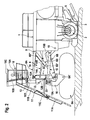
- FIGS. 1 and 3 show in side and top view of a machine for the exploitation of deposits in open pit mining, which is referred to below as a surface miner.
- the surface miner for cutting rocks has a chassis 1, which is designed as a rigid welded construction.
- a cutting device 2 is arranged with a cutting roller 3, which is provided with tool holders, not shown, for receiving the cutting tools, not shown.
- the drive unit, not shown with the internal combustion engine for driving the machine is located in the chassis 1.
- the mechanical power transmission from the engine to the cutting or milling drum is located on the so-called drive side of the machine, which in the present embodiment, the left in the direction of the Machine is.
- the cut and shredded material of the cutting roller 3 is received by a loading device 4, which includes a wide receiving tape 5 in the direction of travel behind the cutting roller 3 and a subsequent discharge belt 6 for loading on transport vehicles.
- the discharge belt 6 is height adjustable and can be pivoted on both sides.
- the depth of cut adjustment is made by raising or lowering the chassis 1, which can be moved on two front and two rear crawler tracks 6A and 6B located at the front and rear of the chassis.
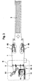
- the height adjustment device of the chassis 1 has parallelogram guides associated with each of the crawler track assemblies 6A, 6B of which the parallelogram guides disposed at the rear of the chassis are designated by the reference numeral 7 and the parallelogram guides disposed at the front of the chassis are designated by the reference numeral 8.
- the four track drives 6A, 6B are suspended from the parallelogram guides 7, 8, whereby the track drives can be moved in a vertical plane with respect to the chassis.
- the chassis 1 is raised or lowered with respect to the floor.
- the front left parallelogram guide 8 for the oscillating suspension of the front left crawler 6A has an upper arm 8A and a lower arm 8B each pivotally connected to the chassis 1 at one end so that the upper and lower arms 8A, 8B each about a horizontal axis 9, 10 are pivotable.
- the other ends of the two links 8A, 8B are hinged to the upper and lower ends of a vertical column 8C.
- the two links 8A, 8B and the column 8C form a parallelogram, wherein the column 8C can be moved in a vertical plane up or down.
- the parallelogram guide 8 For raising or lowering the column 8C, the parallelogram guide 8 has a piston / cylinder arrangement 8D, with one end of the piston 8D 'hinged to the lower end of the column 8C and the one end of the cylinder 8D "of the piston / cylinder arrangement 8D is pivotally connected to the chassis 1.
- the piston of the piston / cylinder assembly By extending or retracting the piston of the piston / cylinder assembly, the column 8C of the parallelogram guide 8 is raised or lowered, unless the drive stands on the ground Floor rises, the chassis is raised or lowered upon actuation of the piston / cylinder assembly 8 D, so that the cutting depth is changed.
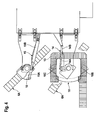
- the surface miner has a driver's seat 10, which is designed as a closed soundproof cab.
- a driver's cab 10 In the driver's cab 10 is a rotatable driver's seat 10A for the operator.
- the cab 10 is glazed all around, so that the operator has visibility on all sides. It has left and right driver's doors 10B, 10C.
- the operator may reach the cab 10 via a length-adjustable ladder 11.
- the ladder 11 consists of a lower and upper segment 11A, 11B, which are hinged together. With a piston / cylinder arrangement 11C, the ladder can be folded up.
- the cab 10 is arranged such that its center of gravity is above the crawler or wheel and substantially above the pillar 8C of the parallelogram 8, with the driver's seat 10A also overlying the pillar. It is accessible from both sides for the operator via a revolving walk 13.
- the parallelogram 8 has relative to the chassis 1 movable components, including the upper and lower arms 8A and 8B and the column 8C, but in principle, the piston / cylinder assembly 8D count.
- the driver's cab 10 is rotatably mounted about a vertical axis on one of the components of the parallelogram guide 8 connected to the chassis 1.
- the chassis is rotatably mounted about a vertical axis on the column 8C of the parallelogram guide 8. Since the drive 6A stands up on the ground, the position of the driver's cab with respect to the ground remains unchanged upon actuation of the piston / cylinder assembly 8D of the parallelogram guide 8.
- the attachment of the driver's cab 10 to the column 8C of the parallelogram guide 8 has the decisive advantage that the driver's cab is decoupled from the chassis 1.
- the piston / cylinder arrangement 8D of the parallelogram guide 8 is a damping element, which reduces the vibrations or vibrations.
- the driver's cab can in principle also be fastened to another movable component of the parallelogram guide, for example to the upper or lower link 8A, 8B. Such attachment proves to be constructive but more expensive, since these components change their position with respect to the ground upon actuation of the piston / cylinder assembly 8D.
- the cab 10 is supported by a fixing device 12 having a vertical pillar 12A fixed to the cab floor panel 10D and a bracket 12B connected to a journal bearing 23 seated on the pillar 8C of the parallelogram guide 8.
- the driver's seat 10A is arranged in the driver's cab 10 on the axis of the column 8C above the parallelogram guide 8. Since the operator is not sitting in the direction of travel in front of the column 8C, but directly above the column, he can see the front chain drives 6A to control the steering movements.
- a piston / cylinder assembly 14 is provided, the piston 14A is pivotally connected to the bracket 12B of the mounting device 12 of the cab 10 and the cylinder 14B pivotally connected to the chassis 1.
- the operator's cab 10 rotates about a vertical axis regardless of the position of the track drive 6A.
- the front crawler tracks 6A are rotated about a vertical axis.
- a further piston / cylinder arrangement 15 is provided for each track drive, the piston 15A is pivotally connected to a bracket 16 of the suspension chassis on which the chassis 6A is suspended around a horizontal axis 6A 'pendulum.
- the bracket 16 of the suspension suspension is in turn fixed to the pillar 8C of the parallelogram guide 8, the pillar 8C being rotatable about a vertical axis at the respective end of the upper and lower links 8A and 8B.
- the driver's cab 10 which is arranged above the column 8C of the parallelogram guide 8, is located substantially above the horizontal axis 6A ', on which the undercarriage 6A is suspended in a pendulum manner.
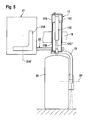
- FIG. 5 shows a schematic representation of the essential components of the suspension of a construction machine, in particular a road milling machine or a recycler.
- the road milling machine or the recycler differ fundamentally from the surface miner in that, instead of a cutting device with a cutting roller, a milling device not shown here is provided with a milling drum. But the milling device with the milling drum generated during operation of the construction machine vibrations or vibrations to which the operator should not be exposed. In addition, there are again the vibrations of the internal combustion engine for driving the machine.
- the chassis suspension of the road milling machine or the recycler differs from the chassis suspension of the surface miner in that instead of a parallelogram a linear guide is provided.
- the linear guide 17 of the road milling machine has an outer hollow cylinder 17A which is fixed to the chassis 18 of the road milling machine.
- FIG. 5 shows only one of the four linear guides 17 of the road milling machine. This is the left linear guide on the drive side of the machine in the direction of travel.
- an inner hollow cylinder 17B is arranged longitudinally displaceably, the lower end of which is connected to a carrier 19, to which a wheel 20 rotatable about the horizontal axis 20 'or also suspended about the axis 20' pivoting chain drive is.
- a piston / cylinder assembly 17C Inside the inner hollow cylinder 17B is a piston / cylinder assembly 17C, the piston 17C 'of which is fixed to the chassis 18 and the cylinder 17C "of which is connected to the carrier 19.
- the piston / cylinder assembly 17C By operating the piston / cylinder assembly 17C, the outer and outer assemblies 17C inner hollow cylinder 17A, 17B moved against each other, so that the chassis 18 is adjusted in relation to the ground in height.
- FIG. 5 shows is in the DE 10 2005 044 211 A1 described in detail, to which reference is expressly made for the purpose of disclosure.
- the driver's stand 21 shown only schematically, which is designed as a closed driver's cab with a driver's seat 21A rotatable about the axis 21A ', again on a component which is movable with respect to the chassis Guide attached, which is here the inner hollow cylinder 17 B of the piston / cylinder assembly 17.
- the attachment does not take place here directly on the inner hollow cylinder 17 B, but with a fastening device 22, with which the driver's cab is mounted pivotably about a vertical axis on the hollow cylinder.
- the cab 21 is not arranged to scale for the sake of clarity to scale next to the linear guide.
- the driver's cab can be connected to the linear guide with a correspondingly formed fastening device or the fastening device can be designed such that the driver's cab is in a suitable position above the wheel, in particular essentially above the axis 20 'of the wheel 20 is located.
- the driver's cab 21 Since the driver's cab 21 is not directly connected to the chassis 18, but is decoupled from the chassis via the linear guide 17, vibrations or vibrations which occur during operation of the milling drum and of the internal combustion engine are suppressed.
- the piston / cylinder arrangement 17C of the linear guide 17 again forms a damping element. From the attachment of the driver's station to the device for height adjustment results here again the advantage that the height the driver's position relative to the ground remains unchanged when the height of the chassis is changed from the ground.
Landscapes
- Engineering & Computer Science (AREA)
- Mining & Mineral Resources (AREA)
- Mechanical Engineering (AREA)
- Architecture (AREA)
- Civil Engineering (AREA)
- Structural Engineering (AREA)
- Body Structure For Vehicles (AREA)
- Road Repair (AREA)
- Drilling And Exploitation, And Mining Machines And Methods (AREA)
- Disintegrating Or Milling (AREA)
Applications Claiming Priority (1)
| Application Number | Priority Date | Filing Date | Title |
|---|---|---|---|
| DE102007028812A DE102007028812B4 (de) | 2007-06-20 | 2007-06-20 | Selbstfahrende Maschine zum Schneiden oder Fräsen, insbesondere Maschine zur Ausbeutung von Lagerstätten im Tagebaubetrieb |
Publications (3)
| Publication Number | Publication Date |
|---|---|
| EP2006449A2 true EP2006449A2 (fr) | 2008-12-24 |
| EP2006449A3 EP2006449A3 (fr) | 2011-01-12 |
| EP2006449B1 EP2006449B1 (fr) | 2013-07-03 |
Family
ID=39762625
Family Applications (1)
| Application Number | Title | Priority Date | Filing Date |
|---|---|---|---|
| EP08009224.0A Active EP2006449B1 (fr) | 2007-06-20 | 2008-05-20 | Machine automobile destinée à couper ou à fraiser, en particulier machine destinée à l'exploitation de gisements à ciel ouvert |
Country Status (5)
| Country | Link |
|---|---|
| US (2) | US8100481B2 (fr) |
| EP (1) | EP2006449B1 (fr) |
| CN (2) | CN101328810B (fr) |
| AU (1) | AU2008202490B2 (fr) |
| DE (1) | DE102007028812B4 (fr) |
Cited By (1)
| Publication number | Priority date | Publication date | Assignee | Title |
|---|---|---|---|---|
| EP2236745A3 (fr) * | 2009-03-20 | 2013-10-02 | Wirtgen GmbH | Engin d'abatage, notamment Surface Miner, ainsi que procédé de démontage et de montage d'un dispositif de transport pour engin d'abatage |
Families Citing this family (24)
| Publication number | Priority date | Publication date | Assignee | Title |
|---|---|---|---|---|
| DE102005044211A1 (de) * | 2005-09-12 | 2007-03-22 | Wirtgen Gmbh | Selbstfahrende Baumaschine, sowie Hubsäule für eine Baumaschine |
| DE102006062129B4 (de) | 2006-12-22 | 2010-08-05 | Wirtgen Gmbh | Straßenbaumaschine sowie Verfahren zur Messung der Frästiefe |
| MX2008013924A (es) * | 2008-09-22 | 2010-05-03 | Angelo Benedetti Inc | Aparato para reciclar asfalto. |
| DE202009003824U1 (de) * | 2009-03-20 | 2010-08-12 | Wirtgen Gmbh | Abbaumaschine, insbesondere Surfac Miner |
| US8459898B2 (en) | 2010-03-26 | 2013-06-11 | Guntert & Zimmerman Const. Div., Inc. | Adjustable bolster swing legs for mounting and aligning and reorienting crawlers for slipform paving machines |
| US9908571B2 (en) | 2010-03-26 | 2018-03-06 | Guntert & Zimmerman Const. Div., Inc. | Adjustable bolster swing legs for slipform paving machines |
| DE102010050441A1 (de) * | 2010-04-11 | 2011-10-13 | Bomag Gmbh | Baumaschine und Verfahren zur Regelung und/oder Überwachung der Frästiefe einer Baumaschine |
| DE102010014649B4 (de) | 2010-04-12 | 2021-05-27 | Liebherr-Components Biberach Gmbh | Selbstfahrender Oberflächenfräser mit elektrischem Fräswalzenantrieb |
| DE102010014644B4 (de) | 2010-04-12 | 2021-07-22 | Liebherr-Components Biberach Gmbh | Selbstfahrende Arbeitsmaschine mit elektrischem Antriebssystem sowie Verfahren zum Betreiben einer solchen |
| DE102010023024A1 (de) | 2010-04-16 | 2011-10-20 | Liebherr-Werk Biberach Gmbh | Selbstfahrender Oberflächenfräser mit fester Lagerung des Fräswalzenantriebs |
| EP2377996B1 (fr) * | 2010-04-16 | 2016-01-13 | Joseph Vögele AG | Suspension de bande oscillante |
| DE102011108016A1 (de) | 2011-07-19 | 2013-01-24 | Liebherr-Components Biberach Gmbh | Selbstfahrender Oberflächenfräser |
| DE102012009310A1 (de) | 2012-05-10 | 2013-11-14 | Bomag Gmbh | Baumaschine zum Bearbeiten einer Fahrbahnoberfläche |
| US8991832B2 (en) * | 2012-05-11 | 2015-03-31 | Doefer Companies | Double-acting suspension axle assembly for heavy load transporters |
| CN103599838B (zh) * | 2013-12-02 | 2015-06-17 | 北方重工集团有限公司 | 一种矿用自移式破碎设备的悬挂式回转变幅装置 |
| DE102014010488B4 (de) * | 2014-07-15 | 2022-12-01 | Bomag Gmbh | Heckrotorfräse mit bewegbarem Aufstieg |
| CN104295295B (zh) * | 2014-11-15 | 2016-06-01 | 辽宁鑫众科技股份有限公司 | 大坡度凿岩掘进机 |
| CN105986822A (zh) * | 2015-01-28 | 2016-10-05 | 山东重拓机械股份有限公司 | 全自动露天采矿机 |
| CN105926420A (zh) * | 2016-04-27 | 2016-09-07 | 河南省路科威公路机械制造有限公司 | 一种新型铣刨机的平衡摇臂装置及应用方法 |
| DE102017009248B4 (de) * | 2017-01-02 | 2020-10-01 | Bomag Gmbh | Kleinfertiger |
| CN106703810A (zh) * | 2017-03-03 | 2017-05-24 | 胡沿东 | 一种采矿机 |
| DE102017208777A1 (de) * | 2017-05-23 | 2018-11-29 | Wirtgen Gmbh | Bodenbearbeitungsmaschine, deren rotierbare Arbeitsvorrichtung zur Montage an die Maschine mit einem Bord-Aktuator in ihre Betriebsposition bringbar ist |
| CN110004808A (zh) * | 2019-04-10 | 2019-07-12 | 安徽开源路桥有限责任公司 | 新老路搭接反射裂缝施工机械及路面施工方法 |
| CN113756797B (zh) * | 2021-09-23 | 2024-02-02 | 云南滇东雨汪能源有限公司 | 一种煤矿开采用岩壁钻孔机 |
Citations (3)
| Publication number | Priority date | Publication date | Assignee | Title |
|---|---|---|---|---|
| DE4017107A1 (de) | 1989-06-20 | 1991-03-28 | Gutehoffnungshuette Man | Stetig arbeitendes gewinnungsgeraet fuer tagebaue mit einem walzenfoermigen gewinnungsorgan |
| EP0744495A2 (fr) | 1995-04-03 | 1996-11-27 | Trencor, Inc. | Dispositif de carrière |
| DE102005044211A1 (de) | 2005-09-12 | 2007-03-22 | Wirtgen Gmbh | Selbstfahrende Baumaschine, sowie Hubsäule für eine Baumaschine |
Family Cites Families (3)
| Publication number | Priority date | Publication date | Assignee | Title |
|---|---|---|---|---|
| US3664448A (en) * | 1970-05-06 | 1972-05-23 | Rex Chainbelt Inc | Vehicle for carrying agricultural or construction tools and the like |
| US3896989A (en) * | 1972-06-09 | 1975-07-29 | Engelhard Min & Chem | Pavement grooving machine including a cutting blade guidance system |
| US20080111327A1 (en) * | 2006-11-13 | 2008-05-15 | Rhodes Design And Development Corporation | Transport device capable of adjustment to maintain load planarity |
-
2007
- 2007-06-20 DE DE102007028812A patent/DE102007028812B4/de active Active
-
2008
- 2008-05-20 EP EP08009224.0A patent/EP2006449B1/fr active Active
- 2008-06-04 AU AU2008202490A patent/AU2008202490B2/en active Active
- 2008-06-12 US US12/138,116 patent/US8100481B2/en active Active
- 2008-06-20 CN CN2008101269950A patent/CN101328810B/zh active Active
- 2008-06-20 CN CNU2008201266159U patent/CN201258743Y/zh not_active Expired - Lifetime
-
2011
- 2011-12-20 US US13/331,806 patent/US8534764B2/en active Active
Patent Citations (3)
| Publication number | Priority date | Publication date | Assignee | Title |
|---|---|---|---|---|
| DE4017107A1 (de) | 1989-06-20 | 1991-03-28 | Gutehoffnungshuette Man | Stetig arbeitendes gewinnungsgeraet fuer tagebaue mit einem walzenfoermigen gewinnungsorgan |
| EP0744495A2 (fr) | 1995-04-03 | 1996-11-27 | Trencor, Inc. | Dispositif de carrière |
| DE102005044211A1 (de) | 2005-09-12 | 2007-03-22 | Wirtgen Gmbh | Selbstfahrende Baumaschine, sowie Hubsäule für eine Baumaschine |
Cited By (1)
| Publication number | Priority date | Publication date | Assignee | Title |
|---|---|---|---|---|
| EP2236745A3 (fr) * | 2009-03-20 | 2013-10-02 | Wirtgen GmbH | Engin d'abatage, notamment Surface Miner, ainsi que procédé de démontage et de montage d'un dispositif de transport pour engin d'abatage |
Also Published As
| Publication number | Publication date |
|---|---|
| US8534764B2 (en) | 2013-09-17 |
| US20080315666A1 (en) | 2008-12-25 |
| DE102007028812A1 (de) | 2008-12-24 |
| EP2006449B1 (fr) | 2013-07-03 |
| CN101328810A (zh) | 2008-12-24 |
| EP2006449A3 (fr) | 2011-01-12 |
| CN201258743Y (zh) | 2009-06-17 |
| CN101328810B (zh) | 2011-12-07 |
| DE102007028812B4 (de) | 2009-08-20 |
| US8100481B2 (en) | 2012-01-24 |
| AU2008202490A1 (en) | 2009-01-22 |
| US20120146389A1 (en) | 2012-06-14 |
| AU2008202490B2 (en) | 2014-05-29 |
Similar Documents
| Publication | Publication Date | Title |
|---|---|---|
| EP2006449B1 (fr) | Machine automobile destinée à couper ou à fraiser, en particulier machine destinée à l'exploitation de gisements à ciel ouvert | |
| EP3489416B1 (fr) | Machine de traitement du sol avec un dispositif deployable et retractable associant pare-brise et toit protecteur et procédé pour modifier la hauteur de cette machine de traitement du sol | |
| EP3103928B1 (fr) | Vehicule de chantier dote d'un chassis basculant | |
| DE102015007562B4 (de) | Selbstfahrende Bodenfräsmaschine, insbesondere Straßenfräse, Recycler, Stabilisierer oder Surface-Miner, mit integrierter Wartungsplatte | |
| DE2630457A1 (de) | Planier-fraesmaschine | |
| DE112016000646T5 (de) | Bewegungsvorrichtung für gegengewicht | |
| EP1958799A1 (fr) | Suspension d'essieu pour poids lourds | |
| DE112012003460T5 (de) | Wischervorrichtung, zu öffnendes/schließendes Schutzgitter mit Wischervorrichtung sowieFührerhaus für Baumaschine | |
| DE69924919T2 (de) | Befestigung für einen rotierenden Besen | |
| DE102016010660A1 (de) | Selbstfahrende Maschine, insbesondere Baumaschine, mit verstellbarer Fahrerkabine sowie Verfahren zum Verstellen einer Fahrerkabine einer selbstfahrenden Maschine | |
| DE102012101109B4 (de) | Geräteträger für Reinigungsgeräte mit Mittenantrieb zum Frontanbau | |
| EP2122069B1 (fr) | Engin de terrassement | |
| DE3920011C2 (fr) | ||
| DE2815019C2 (fr) | ||
| WO2022122549A1 (fr) | Organe de roulement comprenant un entraînement à chenilles ou un entraînement à roues pour des véhicules, des machines et des dispositifs | |
| DE3029221C2 (fr) | ||
| DE60119131T2 (de) | Siebvorrichtung mit selbstantrieb | |
| EP0663478A1 (fr) | Combinaison d'une excavatrice avec un dispositif vibreur | |
| DE102004052760A1 (de) | Tragvorrichtung für die Aufhängung eines Walzenbesens an einem Kehrfahrzeug | |
| EP4083326B1 (fr) | Engin de génie civil | |
| EP0855572A1 (fr) | Dispositif de déminage des mines de surface | |
| DE3834505C2 (de) | Bagger mit einem Steuereinheiten enthaltenden Fahrerhaus | |
| DE2127091A1 (de) | Steuereinrichtung für Fahrzeuge, insbesondere fur Straßenwalzen | |
| DE1484652C (de) | Fahrbares Gerät zum Räumen von Gräben | |
| DE20102185U1 (de) | Vorrichtung zum Einsanden von Verbund- und Pflastersteinen |
Legal Events
| Date | Code | Title | Description |
|---|---|---|---|
| PUAI | Public reference made under article 153(3) epc to a published international application that has entered the european phase |
Free format text: ORIGINAL CODE: 0009012 |
|
| AK | Designated contracting states |
Kind code of ref document: A2 Designated state(s): AT BE BG CH CY CZ DE DK EE ES FI FR GB GR HR HU IE IS IT LI LT LU LV MC MT NL NO PL PT RO SE SI SK TR |
|
| AX | Request for extension of the european patent |
Extension state: AL BA MK RS |
|
| PUAL | Search report despatched |
Free format text: ORIGINAL CODE: 0009013 |
|
| AK | Designated contracting states |
Kind code of ref document: A3 Designated state(s): AT BE BG CH CY CZ DE DK EE ES FI FR GB GR HR HU IE IS IT LI LT LU LV MC MT NL NO PL PT RO SE SI SK TR |
|
| AX | Request for extension of the european patent |
Extension state: AL BA MK RS |
|
| 17P | Request for examination filed |
Effective date: 20110701 |
|
| AKX | Designation fees paid |
Designated state(s): AT BE BG CH CY CZ DE DK EE ES FI FR GB GR HR HU IE IS IT LI LT LU LV MC MT NL NO PL PT RO SE SI SK TR |
|
| GRAP | Despatch of communication of intention to grant a patent |
Free format text: ORIGINAL CODE: EPIDOSNIGR1 |
|
| GRAS | Grant fee paid |
Free format text: ORIGINAL CODE: EPIDOSNIGR3 |
|
| GRAA | (expected) grant |
Free format text: ORIGINAL CODE: 0009210 |
|
| AK | Designated contracting states |
Kind code of ref document: B1 Designated state(s): AT BE BG CH CY CZ DE DK EE ES FI FR GB GR HR HU IE IS IT LI LT LU LV MC MT NL NO PL PT RO SE SI SK TR |
|
| REG | Reference to a national code |
Ref country code: GB Ref legal event code: FG4D Free format text: NOT ENGLISH |
|
| REG | Reference to a national code |
Ref country code: AT Ref legal event code: REF Ref document number: 619863 Country of ref document: AT Kind code of ref document: T Effective date: 20130715 Ref country code: CH Ref legal event code: EP |
|
| REG | Reference to a national code |
Ref country code: IE Ref legal event code: FG4D Free format text: LANGUAGE OF EP DOCUMENT: GERMAN |
|
| REG | Reference to a national code |
Ref country code: DE Ref legal event code: R096 Ref document number: 502008010214 Country of ref document: DE Effective date: 20130822 |
|
| PG25 | Lapsed in a contracting state [announced via postgrant information from national office to epo] |
Ref country code: SI Free format text: LAPSE BECAUSE OF FAILURE TO SUBMIT A TRANSLATION OF THE DESCRIPTION OR TO PAY THE FEE WITHIN THE PRESCRIBED TIME-LIMIT Effective date: 20130703 |
|
| REG | Reference to a national code |
Ref country code: NL Ref legal event code: VDEP Effective date: 20130703 |
|
| REG | Reference to a national code |
Ref country code: LT Ref legal event code: MG4D |
|
| PG25 | Lapsed in a contracting state [announced via postgrant information from national office to epo] |
Ref country code: PT Free format text: LAPSE BECAUSE OF FAILURE TO SUBMIT A TRANSLATION OF THE DESCRIPTION OR TO PAY THE FEE WITHIN THE PRESCRIBED TIME-LIMIT Effective date: 20131104 Ref country code: CY Free format text: LAPSE BECAUSE OF FAILURE TO SUBMIT A TRANSLATION OF THE DESCRIPTION OR TO PAY THE FEE WITHIN THE PRESCRIBED TIME-LIMIT Effective date: 20130619 Ref country code: HR Free format text: LAPSE BECAUSE OF FAILURE TO SUBMIT A TRANSLATION OF THE DESCRIPTION OR TO PAY THE FEE WITHIN THE PRESCRIBED TIME-LIMIT Effective date: 20130703 Ref country code: IS Free format text: LAPSE BECAUSE OF FAILURE TO SUBMIT A TRANSLATION OF THE DESCRIPTION OR TO PAY THE FEE WITHIN THE PRESCRIBED TIME-LIMIT Effective date: 20131103 Ref country code: LT Free format text: LAPSE BECAUSE OF FAILURE TO SUBMIT A TRANSLATION OF THE DESCRIPTION OR TO PAY THE FEE WITHIN THE PRESCRIBED TIME-LIMIT Effective date: 20130703 Ref country code: SE Free format text: LAPSE BECAUSE OF FAILURE TO SUBMIT A TRANSLATION OF THE DESCRIPTION OR TO PAY THE FEE WITHIN THE PRESCRIBED TIME-LIMIT Effective date: 20130703 Ref country code: NO Free format text: LAPSE BECAUSE OF FAILURE TO SUBMIT A TRANSLATION OF THE DESCRIPTION OR TO PAY THE FEE WITHIN THE PRESCRIBED TIME-LIMIT Effective date: 20131003 |
|
| PG25 | Lapsed in a contracting state [announced via postgrant information from national office to epo] |
Ref country code: PL Free format text: LAPSE BECAUSE OF FAILURE TO SUBMIT A TRANSLATION OF THE DESCRIPTION OR TO PAY THE FEE WITHIN THE PRESCRIBED TIME-LIMIT Effective date: 20130703 Ref country code: FI Free format text: LAPSE BECAUSE OF FAILURE TO SUBMIT A TRANSLATION OF THE DESCRIPTION OR TO PAY THE FEE WITHIN THE PRESCRIBED TIME-LIMIT Effective date: 20130703 Ref country code: NL Free format text: LAPSE BECAUSE OF FAILURE TO SUBMIT A TRANSLATION OF THE DESCRIPTION OR TO PAY THE FEE WITHIN THE PRESCRIBED TIME-LIMIT Effective date: 20130703 Ref country code: ES Free format text: LAPSE BECAUSE OF FAILURE TO SUBMIT A TRANSLATION OF THE DESCRIPTION OR TO PAY THE FEE WITHIN THE PRESCRIBED TIME-LIMIT Effective date: 20131014 Ref country code: LV Free format text: LAPSE BECAUSE OF FAILURE TO SUBMIT A TRANSLATION OF THE DESCRIPTION OR TO PAY THE FEE WITHIN THE PRESCRIBED TIME-LIMIT Effective date: 20130703 Ref country code: GR Free format text: LAPSE BECAUSE OF FAILURE TO SUBMIT A TRANSLATION OF THE DESCRIPTION OR TO PAY THE FEE WITHIN THE PRESCRIBED TIME-LIMIT Effective date: 20131004 |
|
| PG25 | Lapsed in a contracting state [announced via postgrant information from national office to epo] |
Ref country code: CY Free format text: LAPSE BECAUSE OF FAILURE TO SUBMIT A TRANSLATION OF THE DESCRIPTION OR TO PAY THE FEE WITHIN THE PRESCRIBED TIME-LIMIT Effective date: 20130703 |
|
| PG25 | Lapsed in a contracting state [announced via postgrant information from national office to epo] |
Ref country code: EE Free format text: LAPSE BECAUSE OF FAILURE TO SUBMIT A TRANSLATION OF THE DESCRIPTION OR TO PAY THE FEE WITHIN THE PRESCRIBED TIME-LIMIT Effective date: 20130703 Ref country code: RO Free format text: LAPSE BECAUSE OF FAILURE TO SUBMIT A TRANSLATION OF THE DESCRIPTION OR TO PAY THE FEE WITHIN THE PRESCRIBED TIME-LIMIT Effective date: 20130703 Ref country code: DK Free format text: LAPSE BECAUSE OF FAILURE TO SUBMIT A TRANSLATION OF THE DESCRIPTION OR TO PAY THE FEE WITHIN THE PRESCRIBED TIME-LIMIT Effective date: 20130703 Ref country code: SK Free format text: LAPSE BECAUSE OF FAILURE TO SUBMIT A TRANSLATION OF THE DESCRIPTION OR TO PAY THE FEE WITHIN THE PRESCRIBED TIME-LIMIT Effective date: 20130703 Ref country code: CZ Free format text: LAPSE BECAUSE OF FAILURE TO SUBMIT A TRANSLATION OF THE DESCRIPTION OR TO PAY THE FEE WITHIN THE PRESCRIBED TIME-LIMIT Effective date: 20130703 |
|
| PLBE | No opposition filed within time limit |
Free format text: ORIGINAL CODE: 0009261 |
|
| STAA | Information on the status of an ep patent application or granted ep patent |
Free format text: STATUS: NO OPPOSITION FILED WITHIN TIME LIMIT |
|
| PG25 | Lapsed in a contracting state [announced via postgrant information from national office to epo] |
Ref country code: IT Free format text: LAPSE BECAUSE OF FAILURE TO SUBMIT A TRANSLATION OF THE DESCRIPTION OR TO PAY THE FEE WITHIN THE PRESCRIBED TIME-LIMIT Effective date: 20130703 |
|
| 26N | No opposition filed |
Effective date: 20140404 |
|
| REG | Reference to a national code |
Ref country code: DE Ref legal event code: R097 Ref document number: 502008010214 Country of ref document: DE Effective date: 20140404 |
|
| PG25 | Lapsed in a contracting state [announced via postgrant information from national office to epo] |
Ref country code: LU Free format text: LAPSE BECAUSE OF FAILURE TO SUBMIT A TRANSLATION OF THE DESCRIPTION OR TO PAY THE FEE WITHIN THE PRESCRIBED TIME-LIMIT Effective date: 20140520 |
|
| REG | Reference to a national code |
Ref country code: CH Ref legal event code: PL |
|
| PG25 | Lapsed in a contracting state [announced via postgrant information from national office to epo] |
Ref country code: MC Free format text: LAPSE BECAUSE OF FAILURE TO SUBMIT A TRANSLATION OF THE DESCRIPTION OR TO PAY THE FEE WITHIN THE PRESCRIBED TIME-LIMIT Effective date: 20130703 Ref country code: CH Free format text: LAPSE BECAUSE OF NON-PAYMENT OF DUE FEES Effective date: 20140531 Ref country code: LI Free format text: LAPSE BECAUSE OF NON-PAYMENT OF DUE FEES Effective date: 20140531 |
|
| REG | Reference to a national code |
Ref country code: IE Ref legal event code: MM4A |
|
| PG25 | Lapsed in a contracting state [announced via postgrant information from national office to epo] |
Ref country code: IE Free format text: LAPSE BECAUSE OF NON-PAYMENT OF DUE FEES Effective date: 20140520 |
|
| REG | Reference to a national code |
Ref country code: FR Ref legal event code: PLFP Year of fee payment: 8 |
|
| REG | Reference to a national code |
Ref country code: AT Ref legal event code: MM01 Ref document number: 619863 Country of ref document: AT Kind code of ref document: T Effective date: 20140520 |
|
| PG25 | Lapsed in a contracting state [announced via postgrant information from national office to epo] |
Ref country code: AT Free format text: LAPSE BECAUSE OF NON-PAYMENT OF DUE FEES Effective date: 20140520 |
|
| PG25 | Lapsed in a contracting state [announced via postgrant information from national office to epo] |
Ref country code: MT Free format text: LAPSE BECAUSE OF FAILURE TO SUBMIT A TRANSLATION OF THE DESCRIPTION OR TO PAY THE FEE WITHIN THE PRESCRIBED TIME-LIMIT Effective date: 20130703 |
|
| REG | Reference to a national code |
Ref country code: FR Ref legal event code: PLFP Year of fee payment: 9 |
|
| PG25 | Lapsed in a contracting state [announced via postgrant information from national office to epo] |
Ref country code: BG Free format text: LAPSE BECAUSE OF FAILURE TO SUBMIT A TRANSLATION OF THE DESCRIPTION OR TO PAY THE FEE WITHIN THE PRESCRIBED TIME-LIMIT Effective date: 20130703 |
|
| PG25 | Lapsed in a contracting state [announced via postgrant information from national office to epo] |
Ref country code: HU Free format text: LAPSE BECAUSE OF FAILURE TO SUBMIT A TRANSLATION OF THE DESCRIPTION OR TO PAY THE FEE WITHIN THE PRESCRIBED TIME-LIMIT; INVALID AB INITIO Effective date: 20080520 Ref country code: BE Free format text: LAPSE BECAUSE OF FAILURE TO SUBMIT A TRANSLATION OF THE DESCRIPTION OR TO PAY THE FEE WITHIN THE PRESCRIBED TIME-LIMIT Effective date: 20140531 Ref country code: TR Free format text: LAPSE BECAUSE OF FAILURE TO SUBMIT A TRANSLATION OF THE DESCRIPTION OR TO PAY THE FEE WITHIN THE PRESCRIBED TIME-LIMIT Effective date: 20130703 |
|
| REG | Reference to a national code |
Ref country code: FR Ref legal event code: PLFP Year of fee payment: 10 |
|
| REG | Reference to a national code |
Ref country code: FR Ref legal event code: PLFP Year of fee payment: 11 |
|
| P01 | Opt-out of the competence of the unified patent court (upc) registered |
Effective date: 20230525 |
|
| PGFP | Annual fee paid to national office [announced via postgrant information from national office to epo] |
Ref country code: GB Payment date: 20240522 Year of fee payment: 17 |
|
| PGFP | Annual fee paid to national office [announced via postgrant information from national office to epo] |
Ref country code: DE Payment date: 20240517 Year of fee payment: 17 |
|
| PGFP | Annual fee paid to national office [announced via postgrant information from national office to epo] |
Ref country code: FR Payment date: 20240522 Year of fee payment: 17 |