EP2006048B1 - Machine-outil de meulage - Google Patents
Machine-outil de meulage Download PDFInfo
- Publication number
- EP2006048B1 EP2006048B1 EP07012258A EP07012258A EP2006048B1 EP 2006048 B1 EP2006048 B1 EP 2006048B1 EP 07012258 A EP07012258 A EP 07012258A EP 07012258 A EP07012258 A EP 07012258A EP 2006048 B1 EP2006048 B1 EP 2006048B1
- Authority
- EP
- European Patent Office
- Prior art keywords
- grinding tool
- grinding
- tool device
- grinding surface
- cover
- Prior art date
- Legal status (The legal status is an assumption and is not a legal conclusion. Google has not performed a legal analysis and makes no representation as to the accuracy of the status listed.)
- Not-in-force
Links
Images


Classifications
-
- B—PERFORMING OPERATIONS; TRANSPORTING
- B24—GRINDING; POLISHING
- B24B—MACHINES, DEVICES, OR PROCESSES FOR GRINDING OR POLISHING; DRESSING OR CONDITIONING OF ABRADING SURFACES; FEEDING OF GRINDING, POLISHING, OR LAPPING AGENTS
- B24B23/00—Portable grinding machines, e.g. hand-guided; Accessories therefor
- B24B23/04—Portable grinding machines, e.g. hand-guided; Accessories therefor with oscillating grinding tools; Accessories therefor
-
- B—PERFORMING OPERATIONS; TRANSPORTING
- B24—GRINDING; POLISHING
- B24B—MACHINES, DEVICES, OR PROCESSES FOR GRINDING OR POLISHING; DRESSING OR CONDITIONING OF ABRADING SURFACES; FEEDING OF GRINDING, POLISHING, OR LAPPING AGENTS
- B24B19/00—Single-purpose machines or devices for particular grinding operations not covered by any other main group
- B24B19/26—Single-purpose machines or devices for particular grinding operations not covered by any other main group for grinding workpieces with arcuate surfaces, e.g. parts of car bodies, bumpers or magnetic recording heads
-
- B—PERFORMING OPERATIONS; TRANSPORTING
- B24—GRINDING; POLISHING
- B24B—MACHINES, DEVICES, OR PROCESSES FOR GRINDING OR POLISHING; DRESSING OR CONDITIONING OF ABRADING SURFACES; FEEDING OF GRINDING, POLISHING, OR LAPPING AGENTS
- B24B55/00—Safety devices for grinding or polishing machines; Accessories fitted to grinding or polishing machines for keeping tools or parts of the machine in good working condition
- B24B55/04—Protective covers for the grinding wheel
- B24B55/05—Protective covers for the grinding wheel specially designed for portable grinding machines
- B24B55/055—Protective covers for the grinding wheel specially designed for portable grinding machines with oscillating tools
Definitions
- the invention relates to a grinding tool device with at least one flexibly flexible eccentrically reciprocatingly drivable grinding tool.
- Such grinding tool devices are in the form of so-called eccentric and Handschwingschleifern for example from DE 101 44 274 A1 known.
- US-A-1 761 059 discloses a grinding tool apparatus with two parallel juxtaposed grinding surfaces, each formed by a single face 50. These two faces 50 and grinding surfaces are driven eccentrically and move parallel and opposite to each other back and forth.
- a composite of a leather strip 41 and a metal strip 39 forms both a sliding guide for each grinding surface and a covering the grinding tool cover, wherein by applying manual pressure on the cover, an adjustment of the grinding tool is achieved on a surface of a workpiece to be machined.
- the arrangement of two parallel juxtaposed and mutually reciprocally driven grinding surfaces can not achieve a satisfactory work result with curved surfaces.
- the object of the invention is to propose a grinding tool device with which the surface of a curved uneven workpiece can be machined.
- a particular advantage of the manually grippable and flexible bendable cover is that it allows a user to grasp and guide the abrasive tooling in close proximity to the abrasive surface. He can actively control the contact pressure of the grinding surface by exerting force of his fingers or his handball and edit different curved surfaces with one and the same grinding tool.
- the cover also overlaps the grinding tool on the outside edge. This leads to a high level of operating safety and prevents injuries. In addition, removed material is retained from escaping to the outside, so that a strong dust generation is avoided.
- Another embodiment of the grinding tool device provides that the cover is detachably connected to a housing. If the cover is defective, it can easily be removed from the grinding tool and replaced with a new one.
- an elastically yielding means is arranged between the cover and the grinding tool, which transmits a pressure generated by manual actuation to an abrasive surface of the grinding tool.
- the elastically resilient means dampens vibrations occurring during operation. This reduction of vibrations leads to a quiet guidance of the grinding tool device.
- the elastically yielding means is connected to the cover, in particular detachably connected.
- the elastically yielding means comprises an elastomer, in particular a silicone composite part.
- silicone composite parts makes it possible to manufacture the elastically yielding agent particularly wear-resistant and cost-effective.
- an embodiment of the grinding tool is preferred, which is characterized in that the elastically resilient means on at least one side in Has direction on the grinding tool protruding elevations.
- the elevations may be rib-like structures that lie flat or line-like on one or both sides.
- the elevations are formed like a column and are formed in particular of circular or polygonal columns.
- the elastically yielding means is formed in several pieces.
- the elastically yielding means is thus composed of various separate items together. It is particularly advantageous in this case that no elastically yielding means designed only for a specific grinding tool device has to be provided.
- the separate items can thus form the resilient means for different grinding tool devices.
- a preferred embodiment of the tool device provides that the elastically yielding means is supported with the elevations on at least a partial surface of a wearer having a grinding surface.
- the elastically yielding means is thus supported with one side opposite the cover and with the other side opposite a carrier.
- an embodiment of the grinding tool device in which the cover communicates with a suction device, so that removed material is sucked.
- the cover is connectable to a suction device and preferably has at least one opening through which the removed material can be sucked off. It is particularly advantageous that the removed material is removed from the work area and the grinding surfaces can work very effectively.
- the elastically yielding means has at least one opening for a suction device.
- the abraded material can thus be passed through the elastically yielding means to the cover communicating with a suction device.
- the Schläftechnikmaschine has a first grinding surface, wherein the first grinding surface has flexible flexible partial surfaces and wherein the partial surfaces are formed by open-edge separations in the first grinding surface, so that the partial surfaces are deflected relative to each other.
- a particular advantage of the flexibly flexible partial surfaces of the grinding surface is that they can be pressed onto the curved surface of a workpiece without great effort.
- the partial surfaces nestle against the curved surface. Because the partial surfaces are separated from one another by edge-open separations, one partial surface can be deflected relative to an adjacent partial surface, preferably transversely to the grinding surface.
- the separation can be a separating slot or a larger recess in the grinding surface, forming elongated finger-shaped partial surfaces.
- the grinding tool also has a second grinding surface, the second grinding surface having flexibly flexible partial surfaces which are formed by edge-open separations in the second grinding surface, so that the partial surfaces are movable relative to one another and in that partial surfaces of the second grinding surface are arranged between partial surfaces of the first partial surface.
- a relative movement between the first and second grinding surface can be carried out and thereby a better work result can be achieved.
- a flexibly flexible first carrier assigned to the first grinding surface is arranged on a first eccentric and a flexibly flexible second carrier assigned to the second grinding surface is arranged on a second eccentric.
- the arrangement of the first and second carrier on a first and second eccentric linear or eccentric drive of the grinding surface is realized.
- an embodiment of the grinding tool device is proposed in which the first grinding surface is detachably connected to the first carrier and / or the second grinding surface is releasably connected to the second carrier, in particular by a hook / loop mechanism (Velcro). It is of particular advantage that the grinding surface can be replaced without the carrier having to be replaced. Thus, a particularly user-friendly handling of the grinding tool device is given. In addition, this proves to be cost effective.
- first eccentric and the second eccentric are arranged drivable by a common drive shaft and arranged axially one above the other.
- first grinding surface performs a movement which is a movement of the second grinding surface through 180 °.
- the first eccentric and the second eccentric are arranged offset by 180 ° to each other on the same shaft
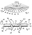
- FIGS. 1 to 8c show an inventive partially and explosively illustrated grinding tool device 2 in an embodiment with a first grinding surface 4 and a second grinding surface 6.
- the first grinding surface 4 is arranged on a first eccentric 8 and the second grinding surface 6 to a second eccentric 10 eccentrically reciprocating driven.
- open-edge separations 12 in the first grinding surface 4 flexibly flexible partial surfaces 14 are formed.
- flexibly flexible partial surfaces 16 of the second grinding surface 6 are formed by edge-open separations in the second grinding surface 6.
- the partial surfaces 16 of the second grinding surface 6 engage in the separations 12 of the first grinding surface 4, and the partial surfaces 14 of the first grinding surface 4 engage in the separations 18 of the second grinding surface 6 so that partial surfaces 14 of the first grinding surface 4 and partial surfaces 16 the second grinding surface 6 are arranged alternately.
- the first grinding surface 4 is arranged on a first carrier 20 and the second grinding surface 6 on a second carrier 22.
- First carrier 20 and second carrier 22 comprise a flexibly flexible material. They are made for example of a sheet metal part. They can be punched from a single item or composed of several individual strips.
- the first grinding surface 4 and the second grinding surface 6 extend with their partial surfaces 14 and 16 substantially radially outwardly. Radially inside, the first grinding surface 4 is connected to the first eccentric 8 and the second grinding surface 6 is connected to the second eccentric 10.
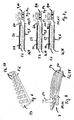
- first eccentric 8 and second eccentric 10 are arranged on a drive shaft 24.
- the second eccentric 10 is pushed onto the drive shaft 24 and axially spaced by a first sleeve 26 against a stop.
- the first eccentric 8 is pushed onto the drive shaft 24 and spaced by a second sleeve 28 to the second eccentric 10.
- a washer 30 and a screw 32 which is screwed into a front-side threaded opening 34 of the drive shaft 24, each an inner eccentric sleeve of the first eccentric 8 and the second eccentric 10 rotatably connected to the drive shaft 24.
- the first eccentric 8 is arranged offset by 180 ° to the second eccentric 10 on the drive shaft 24.
- the offset by 180 ° arrangement of the first eccentric 8 to the second eccentric 10 causes the first grinding surface 4 and the second grinding surface 6 to perform mutually offset eccentric reciprocating movements.
- FIG. 4 shows how the grinding surfaces 4, 6 on the carriers 20, 22 are detachably arranged by means of a flexible sheet 41.
- a hook component 36 is applied on a side facing the grinding surfaces, which can be brought into engagement with a loop component 38 on the back of the grinding surfaces 4, 6 (Velcro).
- the loop component 38 is fixedly arranged on the flat material 41 designed as a stretchable film 40.
- the film 40 has in the region of the separations 12, 18 greatly exaggerated material projections 42.
- an abrasive 44 is attached, for example in the form of an abrasive paper, which forms the grinding surfaces 4, 6.
- FIGS. 5a to 5c a grinding tool device 2 is shown in the processing of curved and flat surfaces.
- a housing 48 in which the drive device is arranged, it has a cover 50.
- the cover 50 encloses both the first grinding surface 4 and the second grinding surface 6 FIGS. 5a to 5c
- the cover 50 is flexibly flexible.
- a user is able to manually guide the grinding tool device 2. For this he can put his hand on the cover 50. By pressure of the user's fingers, the pressure on the grinding surfaces 4, 6 can be increased. From the FIGS. 5a to 5c it can be seen that the grinding tool device 2 according to the invention can also adapt to curved surfaces.
- FIGS. 6-8 show an embodiment of the grinding tool device 2, in which an elastically stretchable means 52 is provided.
- the means 52 has a rear region 54 and as nubs 56 realized protruding elevations 58.
- the elastically stretchable means 52 is supported with its rear region 54 relative to the cover 50 and with its projecting protrusions 58 formed as knobs 56 with respect to a first carrier 20 or to a second carrier 22.
- the means 52 is elastically yielding.
- the means 52 is releasably connected to the housing 48 and the cover 50.
- FIGS. 8a-8c Furthermore, it can be seen that, when the grinding tool device is in operation, only the knobs 56 join in the movement of the grinding surfaces 4, 6.
- the nubs 56 are supported on the supports 20, 22 so that upon manual pressure on the cover 50 of the grinding tool 2 by a user on the knobs 56 a force on the grinding surfaces 4, 6 is transmitted. Thereby the movement becomes the grinding surfaces 4, 6 transferred to the knobs 56, which in the FIGS. 8a to 8c is indicated.
- a manual operation by a user is thus enabled, for example, by deflection of the fingers or the user's handball a contact force on the grinding surfaces 4, 6 transmitted becomes.
- the user can thus easily adjust the grinding surfaces 4,6 of the curvature of the surface of the workpiece to be machined and actively determine the contact pressure.
- the means 52 dampens the vibrations resulting from the movement of the grinding surfaces 4, 6 in that the nubs 56 are elastically yielding and the rear region 54 is immovable during the movement of the grinding surfaces 4, 6. This ensures a smooth running in the course of processing.
Landscapes
- Engineering & Computer Science (AREA)
- Mechanical Engineering (AREA)
- Finish Polishing, Edge Sharpening, And Grinding By Specific Grinding Devices (AREA)
- Mechanical Treatment Of Semiconductor (AREA)
- Grinding-Machine Dressing And Accessory Apparatuses (AREA)
- Polishing Bodies And Polishing Tools (AREA)
Claims (15)
- Appareil avec outil de meulage (2) comportant au moins un outil de meulage souple, pouvant être déplacé de manière excentrique, dans un mouvement de va-et-vient. L'outil de meulage comporte une première surface de meulage (4), la première surface de meulage (4) présentant des fractions souples (14) et les fractions (14) étant constituées de divisions (14), ouvertes sur les bords, réalisées dans la première surface de meulage (4) de sorte que les fractions (14) peuvent être inclinées les unes par rapport aux autres. La première surface de meulage (4) s'étend, avec ses fractions (14), dans une direction sensiblement radiale par rapport à un arbre d'entraînement (24). On a prévu, sur le côté ne faisant pas face à une surface de meulage (4, 6) de l'outil de meulage, une plaque (50) recouvrant l'outil de meulage. La plaque (50) peut être saisie à la main et pliée de sorte que l'exercice d'une pression manuelle sur la plaque (50) permette d'obtenir une adaptation de l'outil de meulage à la superficie d'une pièce d'oeuvre à usiner.
- Appareil avec outil de meulage (2) selon la revendication 1, caractérisé en ce que la plaque (50) recouvre également les bords externes de l'outil de meulage.
- Appareil avec outil de meulage (2) selon l'une quelconque des revendications précédentes, caractérisé en ce que la plaque (50) est rattachée de manière amovible à un boîtier (48).
- Appareil avec outil de meulage (2) selon l'une quelconque des revendications 1 ou 2, caractérisé en ce qu'on a disposé, entre la plaque (50) et l'outil de meulage, un moyen élastiquement déformable (52) qui transmet une pression, produite par l'actionnement manuel, à une surface de meulage (4, 6) de l'outil de meulage.
- Appareil avec outil de meulage (2) selon la revendication 4, caractérisé en ce que le moyen élastiquement déformable (52) est rattaché à la plaque (50), en particulier de manière amovible.
- Appareil avec outil de meulage (2) selon l'une quelconque des revendications précédentes, caractérisé en ce que le moyen élastiquement déformable (52) contient un élastomère, en particulier un composite de silicone.
- Appareil avec outil de meulage (2) selon l'une quelconque des revendications précédentes, caractérisé en ce que le moyen élastiquement déformable (52) présente, sur au moins une face, des saillies (58), en particulier en forme de colonnes, s'avançant en direction de l'outil de meulage.
- Appareil avec outil de meulage (2) selon l'une quelconque des revendications précédentes, caractérisé en ce que le moyen élastiquement déformable (52) est constitué de plusieurs pièces.
- Appareil avec outil de meulage (2) selon l'une quelconque des revendications précédentes, caractérisé en ce que le moyen (52) s'appuie, avec les saillies (58), sur au moins une fraction (14, 16) d'un support (20, 22) présentant une surface de meulage (4, 6).
- Appareil avec outil de meulage (2) selon l'une quelconque des revendications précédentes, caractérisé en ce que la plaque (50) communique avec un dispositif d'aspiration de manière à ce que le matériau enlevé puisse être aspiré.
- Appareil avec outil de meulage (2) selon la revendication 10, caractérisé en ce que le moyen élastiquement déformable (52) comporte au moins un orifice pour un dispositif d'aspiration.
- Appareil avec outil de meulage (2) selon l'une quelconque des revendications précédentes, caractérisé en ce que l'outil de meulage comporte également une seconde surface de meulage (6), la seconde surface de meulage (6) présentant des fractions souples (16) qui sont constituées de divisions (18), ouvertes sur les bords, réalisées dans la seconde surface de meulage (6) de sorte que les fractions (16) peuvent être déplacées les unes par rapport aux autres, et en ce que les fractions (16) de la seconde surface de meulage (6) sont agencées entre les fractions (14) de la première surface de meulage (4).
- Appareil avec outil de meulage (2) selon la revendication 12, caractérisé en ce qu'un premier support souple (20), associé à la première surface de meulage (4), est disposé sur un premier excentrique (8) et un second support souple (22), associé à la seconde surface de meulage (6), est disposé sur un second excentrique (10).
- Appareil avec outil de meulage (2) selon la revendication 13, caractérisé en ce que la première surface de meulage (4) est assemblée de manière amovible au premier support (20) et/ou la seconde surface de meulage (6) est assemblée de manière amovible au second support (22), en particulier par le biais d'un mécanisme crochets/boucles (36, 38), un velcro.
- Appareil avec un outil de meulage (2) selon l'une quelconque des revendications 13 ou 14, caractérisé en ce que le premier excentrique (8) et le second excentrique (10) peuvent être actionnés par un arbre d'entraînement commun (24) et sont agencés l'un sur l'autre dans le sens axial.
Priority Applications (3)
| Application Number | Priority Date | Filing Date | Title |
|---|---|---|---|
| DE502007004649T DE502007004649D1 (de) | 2007-06-22 | 2007-06-22 | Schleifwerkzeuggerät |
| EP07012258A EP2006048B1 (fr) | 2007-06-22 | 2007-06-22 | Machine-outil de meulage |
| AT07012258T ATE476276T1 (de) | 2007-06-22 | 2007-06-22 | Schleifwerkzeuggerät |
Applications Claiming Priority (1)
| Application Number | Priority Date | Filing Date | Title |
|---|---|---|---|
| EP07012258A EP2006048B1 (fr) | 2007-06-22 | 2007-06-22 | Machine-outil de meulage |
Publications (2)
| Publication Number | Publication Date |
|---|---|
| EP2006048A1 EP2006048A1 (fr) | 2008-12-24 |
| EP2006048B1 true EP2006048B1 (fr) | 2010-08-04 |
Family
ID=38473113
Family Applications (1)
| Application Number | Title | Priority Date | Filing Date |
|---|---|---|---|
| EP07012258A Not-in-force EP2006048B1 (fr) | 2007-06-22 | 2007-06-22 | Machine-outil de meulage |
Country Status (3)
| Country | Link |
|---|---|
| EP (1) | EP2006048B1 (fr) |
| AT (1) | ATE476276T1 (fr) |
| DE (1) | DE502007004649D1 (fr) |
Family Cites Families (3)
| Publication number | Priority date | Publication date | Assignee | Title |
|---|---|---|---|---|
| US1761059A (en) * | 1928-12-14 | 1930-06-03 | Norman Machine Tool Co Van | Polishing machine |
| DE19524084A1 (de) * | 1995-07-01 | 1997-01-02 | Bosch Gmbh Robert | Handschleifwerkzeugmaschine und Schleifwerkzeug |
| DE10144274A1 (de) | 2001-09-08 | 2003-03-27 | Bosch Gmbh Robert | Schleifplatte |
-
2007
- 2007-06-22 EP EP07012258A patent/EP2006048B1/fr not_active Not-in-force
- 2007-06-22 DE DE502007004649T patent/DE502007004649D1/de active Active
- 2007-06-22 AT AT07012258T patent/ATE476276T1/de active
Also Published As
| Publication number | Publication date |
|---|---|
| ATE476276T1 (de) | 2010-08-15 |
| DE502007004649D1 (de) | 2010-09-16 |
| EP2006048A1 (fr) | 2008-12-24 |
Similar Documents
| Publication | Publication Date | Title |
|---|---|---|
| EP1520668B1 (fr) | Dispositif de coupe ayant une bague de support déformable élastiquement | |
| EP1964635B1 (fr) | Scie à métaux, en particulier scie sauteuse | |
| DE202011002462U1 (de) | Rohrbandschleifeinheit | |
| EP2262619A1 (fr) | Poignée supplémentaire et machine-outil portative | |
| EP2338616A2 (fr) | Dispositif mécanique pour le nettoyage de barres d'appui de supports de pièces à usiner sur des machines-outils | |
| DE102010044613A1 (de) | Schleifgerät | |
| DE102007062560A1 (de) | Flächenschleifmaschine | |
| DE102012219638A1 (de) | Rohrbandschleifeinheit | |
| EP2327510A1 (fr) | Dispositif de finition | |
| EP3459679A1 (fr) | Dispositif de production d'un finissage non défini sur une surface d'une pièce à usiner métallique dans un processus en continu | |
| DE69313378T2 (de) | Elektrisches Handwerkzeug mit hin- und herangetriebenem Werkzeug | |
| DE1088332B (de) | Flachschneidpresse, insbesondere fuer Zuschnitte aus Pappe | |
| EP1857223B1 (fr) | Actionnement par oscillation doté d'une butée de profondeur et butée de profondeur pour un actionnement par oscillation | |
| EP2006048B1 (fr) | Machine-outil de meulage | |
| WO2016192743A1 (fr) | Poignée d'instrument et instrument manuel pourvu d'une poignée de ce type | |
| DE102010007056A1 (de) | Schleifmittelandruckeinheit und Bandschleifmaschine mit Schleifmittelandruckeinheit | |
| WO2012142644A2 (fr) | Galet amortisseur | |
| EP3969224B1 (fr) | Ponceuse orbitale pourvue d'un dispositif de freinage | |
| EP2006049B1 (fr) | Machine-outil de meulage motorisée | |
| EP2853363A1 (fr) | Outil d'estampillage ou de coupe | |
| EP3124176B1 (fr) | Outil de rectification comprenant un profil de formage pour une meuleuse oscillante | |
| DE10010108C1 (de) | Exentertellerschleifer | |
| EP2006050A1 (fr) | Machine-outil de meulage motorisée | |
| DE102007029574B4 (de) | Leder-Reparaturverfahren und Leder-Stanzvorrichtung | |
| DE102024112677B3 (de) | Chirurgisches Instrument |
Legal Events
| Date | Code | Title | Description |
|---|---|---|---|
| PUAI | Public reference made under article 153(3) epc to a published international application that has entered the european phase |
Free format text: ORIGINAL CODE: 0009012 |
|
| AK | Designated contracting states |
Kind code of ref document: A1 Designated state(s): AT BE BG CH CY CZ DE DK EE ES FI FR GB GR HU IE IS IT LI LT LU LV MC MT NL PL PT RO SE SI SK TR |
|
| AX | Request for extension of the european patent |
Extension state: AL BA HR MK RS |
|
| 17P | Request for examination filed |
Effective date: 20090617 |
|
| 17Q | First examination report despatched |
Effective date: 20090717 |
|
| AKX | Designation fees paid |
Designated state(s): AT BE BG CH CY CZ DE DK EE ES FI FR GB GR HU IE IS IT LI LT LU LV MC MT NL PL PT RO SE SI SK TR |
|
| GRAP | Despatch of communication of intention to grant a patent |
Free format text: ORIGINAL CODE: EPIDOSNIGR1 |
|
| RIN1 | Information on inventor provided before grant (corrected) |
Inventor name: DRECHSEL, FRANK Inventor name: WILKE, DIRK |
|
| GRAS | Grant fee paid |
Free format text: ORIGINAL CODE: EPIDOSNIGR3 |
|
| GRAA | (expected) grant |
Free format text: ORIGINAL CODE: 0009210 |
|
| AK | Designated contracting states |
Kind code of ref document: B1 Designated state(s): AT BE BG CH CY CZ DE DK EE ES FI FR GB GR HU IE IS IT LI LT LU LV MC MT NL PL PT RO SE SI SK TR |
|
| REG | Reference to a national code |
Ref country code: GB Ref legal event code: FG4D Free format text: NOT ENGLISH |
|
| REG | Reference to a national code |
Ref country code: CH Ref legal event code: EP |
|
| REG | Reference to a national code |
Ref country code: IE Ref legal event code: FG4D Free format text: LANGUAGE OF EP DOCUMENT: GERMAN |
|
| REF | Corresponds to: |
Ref document number: 502007004649 Country of ref document: DE Date of ref document: 20100916 Kind code of ref document: P |
|
| REG | Reference to a national code |
Ref country code: NL Ref legal event code: VDEP Effective date: 20100804 |
|
| LTIE | Lt: invalidation of european patent or patent extension |
Effective date: 20100804 |
|
| PG25 | Lapsed in a contracting state [announced via postgrant information from national office to epo] |
Ref country code: NL Free format text: LAPSE BECAUSE OF FAILURE TO SUBMIT A TRANSLATION OF THE DESCRIPTION OR TO PAY THE FEE WITHIN THE PRESCRIBED TIME-LIMIT Effective date: 20100804 Ref country code: FI Free format text: LAPSE BECAUSE OF FAILURE TO SUBMIT A TRANSLATION OF THE DESCRIPTION OR TO PAY THE FEE WITHIN THE PRESCRIBED TIME-LIMIT Effective date: 20100804 Ref country code: LT Free format text: LAPSE BECAUSE OF FAILURE TO SUBMIT A TRANSLATION OF THE DESCRIPTION OR TO PAY THE FEE WITHIN THE PRESCRIBED TIME-LIMIT Effective date: 20100804 |
|
| PG25 | Lapsed in a contracting state [announced via postgrant information from national office to epo] |
Ref country code: PL Free format text: LAPSE BECAUSE OF FAILURE TO SUBMIT A TRANSLATION OF THE DESCRIPTION OR TO PAY THE FEE WITHIN THE PRESCRIBED TIME-LIMIT Effective date: 20100804 Ref country code: IS Free format text: LAPSE BECAUSE OF FAILURE TO SUBMIT A TRANSLATION OF THE DESCRIPTION OR TO PAY THE FEE WITHIN THE PRESCRIBED TIME-LIMIT Effective date: 20101204 Ref country code: CY Free format text: LAPSE BECAUSE OF FAILURE TO SUBMIT A TRANSLATION OF THE DESCRIPTION OR TO PAY THE FEE WITHIN THE PRESCRIBED TIME-LIMIT Effective date: 20100804 Ref country code: BG Free format text: LAPSE BECAUSE OF FAILURE TO SUBMIT A TRANSLATION OF THE DESCRIPTION OR TO PAY THE FEE WITHIN THE PRESCRIBED TIME-LIMIT Effective date: 20101104 Ref country code: SI Free format text: LAPSE BECAUSE OF FAILURE TO SUBMIT A TRANSLATION OF THE DESCRIPTION OR TO PAY THE FEE WITHIN THE PRESCRIBED TIME-LIMIT Effective date: 20100804 Ref country code: PT Free format text: LAPSE BECAUSE OF FAILURE TO SUBMIT A TRANSLATION OF THE DESCRIPTION OR TO PAY THE FEE WITHIN THE PRESCRIBED TIME-LIMIT Effective date: 20101206 |
|
| REG | Reference to a national code |
Ref country code: IE Ref legal event code: FD4D |
|
| PG25 | Lapsed in a contracting state [announced via postgrant information from national office to epo] |
Ref country code: GR Free format text: LAPSE BECAUSE OF FAILURE TO SUBMIT A TRANSLATION OF THE DESCRIPTION OR TO PAY THE FEE WITHIN THE PRESCRIBED TIME-LIMIT Effective date: 20101105 Ref country code: LV Free format text: LAPSE BECAUSE OF FAILURE TO SUBMIT A TRANSLATION OF THE DESCRIPTION OR TO PAY THE FEE WITHIN THE PRESCRIBED TIME-LIMIT Effective date: 20100804 Ref country code: SE Free format text: LAPSE BECAUSE OF FAILURE TO SUBMIT A TRANSLATION OF THE DESCRIPTION OR TO PAY THE FEE WITHIN THE PRESCRIBED TIME-LIMIT Effective date: 20100804 |
|
| PG25 | Lapsed in a contracting state [announced via postgrant information from national office to epo] |
Ref country code: IE Free format text: LAPSE BECAUSE OF FAILURE TO SUBMIT A TRANSLATION OF THE DESCRIPTION OR TO PAY THE FEE WITHIN THE PRESCRIBED TIME-LIMIT Effective date: 20100804 Ref country code: DK Free format text: LAPSE BECAUSE OF FAILURE TO SUBMIT A TRANSLATION OF THE DESCRIPTION OR TO PAY THE FEE WITHIN THE PRESCRIBED TIME-LIMIT Effective date: 20100804 |
|
| PG25 | Lapsed in a contracting state [announced via postgrant information from national office to epo] |
Ref country code: SK Free format text: LAPSE BECAUSE OF FAILURE TO SUBMIT A TRANSLATION OF THE DESCRIPTION OR TO PAY THE FEE WITHIN THE PRESCRIBED TIME-LIMIT Effective date: 20100804 Ref country code: RO Free format text: LAPSE BECAUSE OF FAILURE TO SUBMIT A TRANSLATION OF THE DESCRIPTION OR TO PAY THE FEE WITHIN THE PRESCRIBED TIME-LIMIT Effective date: 20100804 Ref country code: CZ Free format text: LAPSE BECAUSE OF FAILURE TO SUBMIT A TRANSLATION OF THE DESCRIPTION OR TO PAY THE FEE WITHIN THE PRESCRIBED TIME-LIMIT Effective date: 20100804 Ref country code: IT Free format text: LAPSE BECAUSE OF FAILURE TO SUBMIT A TRANSLATION OF THE DESCRIPTION OR TO PAY THE FEE WITHIN THE PRESCRIBED TIME-LIMIT Effective date: 20100804 Ref country code: EE Free format text: LAPSE BECAUSE OF FAILURE TO SUBMIT A TRANSLATION OF THE DESCRIPTION OR TO PAY THE FEE WITHIN THE PRESCRIBED TIME-LIMIT Effective date: 20100804 |
|
| PLBE | No opposition filed within time limit |
Free format text: ORIGINAL CODE: 0009261 |
|
| STAA | Information on the status of an ep patent application or granted ep patent |
Free format text: STATUS: NO OPPOSITION FILED WITHIN TIME LIMIT |
|
| PG25 | Lapsed in a contracting state [announced via postgrant information from national office to epo] |
Ref country code: ES Free format text: LAPSE BECAUSE OF FAILURE TO SUBMIT A TRANSLATION OF THE DESCRIPTION OR TO PAY THE FEE WITHIN THE PRESCRIBED TIME-LIMIT Effective date: 20101115 |
|
| 26N | No opposition filed |
Effective date: 20110506 |
|
| REG | Reference to a national code |
Ref country code: DE Ref legal event code: R097 Ref document number: 502007004649 Country of ref document: DE Effective date: 20110506 |
|
| PG25 | Lapsed in a contracting state [announced via postgrant information from national office to epo] |
Ref country code: MT Free format text: LAPSE BECAUSE OF FAILURE TO SUBMIT A TRANSLATION OF THE DESCRIPTION OR TO PAY THE FEE WITHIN THE PRESCRIBED TIME-LIMIT Effective date: 20100804 |
|
| BERE | Be: lapsed |
Owner name: METABOWERKE G.M.B.H. Effective date: 20110630 |
|
| REG | Reference to a national code |
Ref country code: CH Ref legal event code: PL |
|
| PG25 | Lapsed in a contracting state [announced via postgrant information from national office to epo] |
Ref country code: BE Free format text: LAPSE BECAUSE OF NON-PAYMENT OF DUE FEES Effective date: 20110630 |
|
| PG25 | Lapsed in a contracting state [announced via postgrant information from national office to epo] |
Ref country code: LI Free format text: LAPSE BECAUSE OF NON-PAYMENT OF DUE FEES Effective date: 20110630 Ref country code: CH Free format text: LAPSE BECAUSE OF NON-PAYMENT OF DUE FEES Effective date: 20110630 |
|
| PG25 | Lapsed in a contracting state [announced via postgrant information from national office to epo] |
Ref country code: MC Free format text: LAPSE BECAUSE OF NON-PAYMENT OF DUE FEES Effective date: 20110630 |
|
| PG25 | Lapsed in a contracting state [announced via postgrant information from national office to epo] |
Ref country code: LU Free format text: LAPSE BECAUSE OF NON-PAYMENT OF DUE FEES Effective date: 20110622 |
|
| REG | Reference to a national code |
Ref country code: AT Ref legal event code: MM01 Ref document number: 476276 Country of ref document: AT Kind code of ref document: T Effective date: 20120622 |
|
| PG25 | Lapsed in a contracting state [announced via postgrant information from national office to epo] |
Ref country code: TR Free format text: LAPSE BECAUSE OF FAILURE TO SUBMIT A TRANSLATION OF THE DESCRIPTION OR TO PAY THE FEE WITHIN THE PRESCRIBED TIME-LIMIT Effective date: 20100804 |
|
| PG25 | Lapsed in a contracting state [announced via postgrant information from national office to epo] |
Ref country code: AT Free format text: LAPSE BECAUSE OF NON-PAYMENT OF DUE FEES Effective date: 20120622 Ref country code: HU Free format text: LAPSE BECAUSE OF FAILURE TO SUBMIT A TRANSLATION OF THE DESCRIPTION OR TO PAY THE FEE WITHIN THE PRESCRIBED TIME-LIMIT Effective date: 20100804 |
|
| REG | Reference to a national code |
Ref country code: FR Ref legal event code: PLFP Year of fee payment: 9 |
|
| PGFP | Annual fee paid to national office [announced via postgrant information from national office to epo] |
Ref country code: GB Payment date: 20150623 Year of fee payment: 9 |
|
| PGFP | Annual fee paid to national office [announced via postgrant information from national office to epo] |
Ref country code: FR Payment date: 20150623 Year of fee payment: 9 |
|
| GBPC | Gb: european patent ceased through non-payment of renewal fee |
Effective date: 20160622 |
|
| REG | Reference to a national code |
Ref country code: FR Ref legal event code: ST Effective date: 20170228 |
|
| PG25 | Lapsed in a contracting state [announced via postgrant information from national office to epo] |
Ref country code: FR Free format text: LAPSE BECAUSE OF NON-PAYMENT OF DUE FEES Effective date: 20160630 |
|
| PG25 | Lapsed in a contracting state [announced via postgrant information from national office to epo] |
Ref country code: GB Free format text: LAPSE BECAUSE OF NON-PAYMENT OF DUE FEES Effective date: 20160622 |
|
| PGFP | Annual fee paid to national office [announced via postgrant information from national office to epo] |
Ref country code: DE Payment date: 20180625 Year of fee payment: 12 |
|
| REG | Reference to a national code |
Ref country code: DE Ref legal event code: R119 Ref document number: 502007004649 Country of ref document: DE |
|
| PG25 | Lapsed in a contracting state [announced via postgrant information from national office to epo] |
Ref country code: DE Free format text: LAPSE BECAUSE OF NON-PAYMENT OF DUE FEES Effective date: 20200101 |