EP2005455B1 - Rotationssteuerungsvorrichtung für eine fernbedienung einer beweglichen maschine. - Google Patents
Rotationssteuerungsvorrichtung für eine fernbedienung einer beweglichen maschine. Download PDFInfo
- Publication number
- EP2005455B1 EP2005455B1 EP07731125.6A EP07731125A EP2005455B1 EP 2005455 B1 EP2005455 B1 EP 2005455B1 EP 07731125 A EP07731125 A EP 07731125A EP 2005455 B1 EP2005455 B1 EP 2005455B1
- Authority
- EP
- European Patent Office
- Prior art keywords
- elastic means
- elastic
- moving
- stop
- equilibrium position
- Prior art date
- Legal status (The legal status is an assumption and is not a legal conclusion. Google has not performed a legal analysis and makes no representation as to the accuracy of the status listed.)
- Not-in-force
Links
- 238000004804 winding Methods 0.000 claims description 13
- 230000000903 blocking effect Effects 0.000 claims description 4
- 229920001971 elastomer Polymers 0.000 claims description 3
- 239000000806 elastomer Substances 0.000 claims description 3
- 238000010276 construction Methods 0.000 claims 1
- 208000031968 Cadaver Diseases 0.000 description 8
- 238000000034 method Methods 0.000 description 2
- 230000005355 Hall effect Effects 0.000 description 1
- 230000006835 compression Effects 0.000 description 1
- 238000007906 compression Methods 0.000 description 1
- 230000003247 decreasing effect Effects 0.000 description 1
- 238000001514 detection method Methods 0.000 description 1
- 210000000056 organ Anatomy 0.000 description 1
- 238000004513 sizing Methods 0.000 description 1
Images

Classifications
-
- H—ELECTRICITY
- H01—ELECTRIC ELEMENTS
- H01H—ELECTRIC SWITCHES; RELAYS; SELECTORS; EMERGENCY PROTECTIVE DEVICES
- H01H23/00—Tumbler or rocker switches, i.e. switches characterised by being operated by rocking an operating member in the form of a rocker button
- H01H23/28—Tumbler or rocker switches, i.e. switches characterised by being operated by rocking an operating member in the form of a rocker button with three operating positions
- H01H23/30—Tumbler or rocker switches, i.e. switches characterised by being operated by rocking an operating member in the form of a rocker button with three operating positions with stable centre positions and one or both end positions unstable
-
- G—PHYSICS
- G05—CONTROLLING; REGULATING
- G05G—CONTROL DEVICES OR SYSTEMS INSOFAR AS CHARACTERISED BY MECHANICAL FEATURES ONLY
- G05G5/00—Means for preventing, limiting or returning the movements of parts of a control mechanism, e.g. locking controlling member
- G05G5/05—Means for returning or tending to return controlling members to an inoperative or neutral position, e.g. by providing return springs or resilient end-stops
-
- G—PHYSICS
- G05—CONTROLLING; REGULATING
- G05G—CONTROL DEVICES OR SYSTEMS INSOFAR AS CHARACTERISED BY MECHANICAL FEATURES ONLY
- G05G1/00—Controlling members, e.g. knobs or handles; Assemblies or arrangements thereof; Indicating position of controlling members
- G05G1/04—Controlling members for hand actuation by pivoting movement, e.g. levers
-
- H—ELECTRICITY
- H01—ELECTRIC ELEMENTS
- H01H—ELECTRIC SWITCHES; RELAYS; SELECTORS; EMERGENCY PROTECTIVE DEVICES
- H01H23/00—Tumbler or rocker switches, i.e. switches characterised by being operated by rocking an operating member in the form of a rocker button
- H01H23/02—Details
- H01H23/12—Movable parts; Contacts mounted thereon
- H01H23/14—Tumblers
-
- Y—GENERAL TAGGING OF NEW TECHNOLOGICAL DEVELOPMENTS; GENERAL TAGGING OF CROSS-SECTIONAL TECHNOLOGIES SPANNING OVER SEVERAL SECTIONS OF THE IPC; TECHNICAL SUBJECTS COVERED BY FORMER USPC CROSS-REFERENCE ART COLLECTIONS [XRACs] AND DIGESTS
- Y10—TECHNICAL SUBJECTS COVERED BY FORMER USPC
- Y10T—TECHNICAL SUBJECTS COVERED BY FORMER US CLASSIFICATION
- Y10T74/00—Machine element or mechanism
- Y10T74/20—Control lever and linkage systems
- Y10T74/20396—Hand operated
- Y10T74/20474—Rotatable rod, shaft, or post
Definitions
- the present invention relates to a rotary control device, intended in particular to be fixed on a handle of a remote mobile machine, in particular machinery, agricultural machinery or handling.
- a mobile device remote control comprises, in known manner, a handle movable in at least one degree of freedom with respect to a support, the movement of this handle allowing an operator to control at least one receiving member outside the remote control.
- a first type of device comprises two members, movable in rotation relative to each other about an axis, formed by a body intended to be fixed on a handle of the remote control on the one hand, and a part of on the other hand, the device also comprising elastic return means for returning the actuating portion in the vicinity of an equilibrium position relative to the body from which a user can drive the actuating part in two opposite directions with respect to the equilibrium position.
- the two driving abutments and the two locking abutments form two pairs of abutments belonging to the two members movable in rotation with respect to one another, the two movable arms being in position equilibrium, in contact with two stops of a first of the two pairs, the elastic means being immobilized relative to a first member.
- This type of device makes it possible to provide a simple system for returning to the equilibrium position.
- This residual clearance can be decreased by appropriate sizing of the gap between the stops of the second member.
- the precise dimensioning of this gap increases the price of the parts used.
- a single winding does not make it possible to obtain a simultaneous reliable contact of the elastic means with the four stops of the two pairs of stops respectively belonging to the two members.
- FIGS. 1 and 2 schematically illustrate the relative positioning, in equilibrium position, of the body C with two locking abutments B1 and B2, the actuating part A with two driving abutments B3 and B4, and elastic means E having a single winding and two movable branches.
- a residual clearance J1 or J2 respectively appears, according to the configurations, between the actuating part and the elastic means, or between the body and the elastic means.
- the present invention relates to a device of the first type described above, comprising first elastic means corresponding to the elastic means of a device of this first type, and characterized in that the device also comprises second resilient means taking support, in equilibrium position, on the one hand on a movable branch of the first elastic means, and on the other hand against a bearing portion of the second member.
- the movable branches of the first elastic means are both in contact against the two stops of a first member, and thus immobilized.
- the second elastic means which are supported on the first elastic means, allow, in equilibrium position, to exert an elastic force on the second member, exerted between a stop of this second member, and a bearing portion of this second organ.
- the first member and the first elastic means are thus immobilized relative to each other, the second member is immobilized by the second elastic means, bearing on the first elastic means.
- the device uses elastic means with a simple winding as in the first type of spring described, to maintain a simple spring structure.
- the second elastic means have a stiffness lower than the stiffness of the first elastic means.
- the difference in stiffness between the first and the second elastic means makes it possible to prevent the stresses exerted by the second elastic means from disturbing the holding in position of the first elastic means by the two stops of the first member.
- the second elastic means comprise an elastic tab connected to a movable branch of the first elastic means.
- the elastic tab is connected by a bend to the end of a movable branch of the first elastic means.
- the bearing portion is constituted by an additional stop located on the second member.
- the bearing portion is constituted by a drive or locking stop, the second elastic means extending obliquely with respect to a plane containing the axis of rotation.
- the device comprises an axial abutment limiting the translational movement of the winding in the direction of the axis of rotation.
- the second elastic means are fixed on the second member.
- the second elastic means comprises an elastomer element.
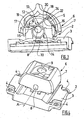
- a rotary control device for a remote control of mobile machine comprises, in known manner, a body 2 intended to be fixed on a handle of the remote control, not shown, the body 2 comprising a first part or base 3 intended to be fixed on the handle by its base, which comprises fastening means 4, in particular slots allowing the passage of fixing screws, and a second part or cover 5, intended to be fixed integrally on the base 3.
- Detection means constituted by a Hall effect sensor 10, are fixed on the base 4, and detect the movement of the magnet 9 facing each other, in order to generate an electrical control signal derived from the movement of the actuating part 6.
- the device comprises a spring 12 which comprises first elastic return means 13 making it possible to return the actuating portion 6 to an equilibrium position E from which a user can drive the actuating part in two opposite directions D1, D2 with respect to the equilibrium position E, by contact with the cabochon 7.
- the first resilient means 13, of a first stiffness k1 comprise a single winding 14, whose loops surround the axis of rotation A, and two movable branches 15, 16 in the extension of the two ends of the winding 14.
- the spring 12 also comprises second elastic means of a second stiffness k2, lower than the first stiffness, constituted by an elastic tab 22 connected by a bend 23 at the end of the second movable arm 16 of the first elastic means 13.
- tab 22 is contained in a plane passing through the axis of rotation A of the actuating part 6.
- the second resilient means are supported on the one hand on the second movable arm 16 as soon as first resilient means, and on the other hand are intended to bear against a bearing portion of the actuating portion 6 constituted by a stop additional 24 located on the actuating part.
- the positioning of the additional stop 24 relative to the second elastic means 22 is such that during a rotation in the direction D1, the additional stop 24 is in contact with the second elastic means 22 before the second drive stop 18 is in contact with the second movable branch 16.
- the additional stop 24 is in contact with the end of the elastic tab 22, which bends, in particular thanks to its elasticity k2 less than that of the first elastic means 13, and then once that the elastic tab 22 is folded, the second driving abutment 18 comes into contact with the second movable arm 16, substantially at the level of the bend 23, and drives this second movable arm 16.
- the two movable arms 15, 16 as well as the stops are arranged asymmetrically with respect to a plane of symmetry of the actuating part in equilibrium position.
- this arrangement makes it possible to use a body of known shape, which has a cylindrical shape only on a limited part of its upper surface, around which the elastic tab 22 can move in rotation.
- the device comprises an axial stop not shown, limiting the translational movement of the winding 14 and the entire spring in the direction of the axis of rotation A of the actuating portion 6.
- the bearing portion is constituted by the extension of the second drive abutment, the support branch having an oblique profile, with respect to a plane passing through the axis of rotation A of the part actuator 6.
- the second elastic means may be constituted by an elastomer element 25, fixed on the actuating portion 6, and intended to be, in equilibrium position, positioned in compression between a bearing portion of the actuating part 6 and a movable branch of the first elastic means.
- the first and second embodiments it is possible to provide a gap between the driving abutments such that the first elastic means are locked in a position of equilibrium between the two drive stops, leaving a gap between the movable branches and the blocking stops.
- the second elastic means must be supported on a support portion of the body to allow to constrain the device in equilibrium position.
Landscapes
- Physics & Mathematics (AREA)
- General Physics & Mathematics (AREA)
- Engineering & Computer Science (AREA)
- Automation & Control Theory (AREA)
- Mechanical Control Devices (AREA)
- Toys (AREA)
- Transmission Devices (AREA)
Claims (10)
- Rotationssteuereinrichtung für eine Fernsteuerung eines beweglichen Fahrzeugs, insbesondere eines Bau-, Landwirtschafts- oder Förderfahrzeugs, die zwei im Verhältnis zueinander um eine Achse (A) rotierend bewegliche Organe aufweist, die von einem Körper (2) gebildet werden, der dazu bestimmt ist, auf einem Griff der Fernsteuerung einerseits und einem Betätigungsteil (6) andererseits befestigt zu sein, wobei die Einrichtung ebenfalls erste elastische Rückstellmittel (13) aufweist, die es erlauben, den Betätigungsteil (6) in die Nähe einer Gleichgewichtsposition (P) im Verhältnis zum Körper (2) zurückzuführen, von der ein Benutzer den Betätigungsteil in zwei entgegengesetzte Richtungen im Verhältnis zur Gleichgewichtsposition betätigen kann, wobei diese ersten elastischen Mittel (13) eine Wicklung (14) und zwei bewegliche Schenkel (15, 16) umfassen, wobei jeder bewegliche Schenkel (15, 16) bestimmt ist, zusammenzuarbeiten mit:- einem Antriebsanschlag (17, 18), der auf dem Betätigungsteil (6) ausgebildet ist und den Antrieb des beweglichen Schenkels (15, 16) in eine Richtung (D1, D2) erlaubt, und- einem Blockieranschlag (19, 20), der auf dem Körper (2) ausgebildet ist, der dazu bestimmt ist, auf dem Körper (2) als Abstützung zu dienen, wenn der Betätigungsteil (6) in die entgegengesetzte Richtung (D1, D2) angetrieben wird,wobei die zwei Antriebsanschläge (17, 18) und die zwei Blockieranschläge (19, 20) zwei Anschlagpaare bilden, die zu den zwei zueinander rotierend beweglichen Organen (2, 6) gehören, wobei die zwei beweglichen Schenkel (15, 16) in Gleichgewichtsposition (P) im Kontakt mit zwei Anschlägen eines ersten der zwei Paare sind, wobei die ersten elastischen Mittel (13) im Verhältnis zu einem ersten Organ (2) blockiert sind,
dadurch gekennzeichnet, dass die Einrichtung ebenfalls zweite elastische Mittel (22) aufweist, die sich in Gleichgewichtsposition einerseits auf einem beweglichen Schenkel (15, 16) der ersten elastischen Mittel (13) und andererseits gegen einen Abstützabschnitt (24) des zweiten Organs (6) abstützen. - Einrichtung nach Anspruch 1, dadurch gekennzeichnet, dass die zweiten elastischen Mittel (22) eine Steifheit (k2) aufweisen, die geringer ist als die Steifheit (k1) der ersten elastischen Mittel (13).
- Einrichtung nach einem der Ansprüche 1 bis 2, dadurch gekennzeichnet, dass die zweiten elastischen Mittel einen elastischen Fuß (22) aufweisen, der mit einem beweglichen Schenkel (16) der ersten elastischen Mittel (13) verbunden ist.
- Einrichtung nach Anspruch 3, dadurch gekennzeichnet, dass der elastische Fuß (22) mittels eines Knies (23) mit dem Ende eines beweglichen Schenkels (16) der ersten elastischen Mittel (13) verbunden ist.
- Einrichtung nach einem der Ansprüche 1 bis 4, dadurch gekennzeichnet, dass der Stützabschnitt (24) von einem zusätzlichen Anschlag gebildet wird, der sich auf dem zweiten Organ (6) befindet.
- Einrichtung nach einem der Ansprüche 1 bis 4, dadurch gekennzeichnet, dass der Stützabschnitt (24) von einem Antriebs- oder Blockieranschlag gebildet wird.
- Einrichtung nach Anspruch 6 und nach Anspruch 3, dadurch gekennzeichnet, dass sich die zweiten elastischen Mittel (22) schräg im Verhältnis zu einer Ebene erstrecken, die die Rotationsachse (A) enthält.
- Einrichtung nach einem der Ansprüche 1 oder 2, dadurch gekennzeichnet, dass die zweiten elastischen Mittel (25) auf dem zweiten Organ befestigt sind.
- Einrichtung nach Anspruch 8, dadurch gekennzeichnet, dass die zweiten elastischen Mittel ein Elastomerelement (25) aufweisen.
- Einrichtung nach einem der Ansprüche 1 bis 8, dadurch gekennzeichnet, dass die Einrichtung einen axialen Anschlag aufweist, der die Verlagerungsbewegung der Wicklung in die Richtung der Rotationsachse begrenzt.
Applications Claiming Priority (2)
| Application Number | Priority Date | Filing Date | Title |
|---|---|---|---|
| FR0603232A FR2899995B1 (fr) | 2006-04-12 | 2006-04-12 | Dispositif de controle rotatif pour une telecommande d'engin mobile, en particulier engin de travaux publics, engin agricole ou de manutention |
| PCT/FR2007/000429 WO2007116132A1 (fr) | 2006-04-12 | 2007-03-12 | Dispositif de controle rotatif pour une telecommande d'engin mobile |
Publications (2)
| Publication Number | Publication Date |
|---|---|
| EP2005455A1 EP2005455A1 (de) | 2008-12-24 |
| EP2005455B1 true EP2005455B1 (de) | 2013-11-13 |
Family
ID=37429291
Family Applications (1)
| Application Number | Title | Priority Date | Filing Date |
|---|---|---|---|
| EP07731125.6A Not-in-force EP2005455B1 (de) | 2006-04-12 | 2007-03-12 | Rotationssteuerungsvorrichtung für eine fernbedienung einer beweglichen maschine. |
Country Status (6)
| Country | Link |
|---|---|
| US (1) | US8030587B2 (de) |
| EP (1) | EP2005455B1 (de) |
| JP (1) | JP5331677B2 (de) |
| CN (1) | CN101421807B (de) |
| FR (1) | FR2899995B1 (de) |
| WO (1) | WO2007116132A1 (de) |
Families Citing this family (8)
| Publication number | Priority date | Publication date | Assignee | Title |
|---|---|---|---|---|
| DE102008033738A1 (de) * | 2008-07-15 | 2010-01-21 | CoActive Technologies, Inc., Greenwich | Wippschalter |
| FR2973527B1 (fr) | 2011-04-04 | 2013-03-29 | Bosch Rexroth Dsi Sas | Rappel au neutre par double ressort |
| JP5769339B2 (ja) * | 2011-08-03 | 2015-08-26 | アルプス電気株式会社 | 磁気式スイッチ装置 |
| FR3051953A1 (fr) * | 2016-05-30 | 2017-12-01 | Bosch Gmbh Robert | Dispositif de pivot a compensation de jeu et telecommande ainsi equipee |
| JP6757187B2 (ja) * | 2016-06-15 | 2020-09-16 | 川崎重工業株式会社 | 電気レバー装置 |
| FR3075457B1 (fr) * | 2017-12-19 | 2019-11-15 | Airbus Helicopters | Mecanisme de commande electrique et aeronef |
| FR3108773B1 (fr) * | 2020-03-27 | 2022-12-16 | Crouzet Automatismes | Interface homme-machine |
| CN113394044B (zh) * | 2021-06-29 | 2023-03-21 | 歌尔科技有限公司 | 开关组件和电子设备 |
Family Cites Families (14)
| Publication number | Priority date | Publication date | Assignee | Title |
|---|---|---|---|---|
| DE871782C (de) * | 1943-06-19 | 1953-03-26 | Stotz Kontakt Gmbh | Elektrischer Installationsschalter mit Rueckholfeder |
| US3329785A (en) * | 1963-10-09 | 1967-07-04 | Gen Motors Corp | Rectangular conductor harness means and attachments |
| US3410971A (en) * | 1967-02-23 | 1968-11-12 | Gen Motors Corp | Double throw, snap acting electric switch |
| JPS60164184U (ja) * | 1984-04-11 | 1985-10-31 | 三菱農機株式会社 | 切換バルブの中立位置復元装置 |
| JPS6183230U (de) * | 1984-11-08 | 1986-06-02 | ||
| JP3911774B2 (ja) * | 1997-07-16 | 2007-05-09 | 松下電器産業株式会社 | プッシュ機構付スライドスイッチ及びその組立て方法 |
| JPH1173840A (ja) * | 1997-08-28 | 1999-03-16 | Harness Sogo Gijutsu Kenkyusho:Kk | スイッチ |
| EP0990245B1 (de) * | 1998-04-15 | 2006-05-31 | Koninklijke Philips Electronics N.V. | Kippschalter |
| JP2001163470A (ja) * | 1999-12-15 | 2001-06-19 | Canon Inc | シート搬送装置および画像形成装置 |
| DE10117597C1 (de) * | 2001-04-07 | 2002-11-28 | Itt Mfg Enterprises Inc | Wippschalter |
| JP4208445B2 (ja) * | 2001-09-13 | 2009-01-14 | 富士フイルム株式会社 | 揺動式操作装置 |
| JP3759033B2 (ja) * | 2001-12-25 | 2006-03-22 | 帝国通信工業株式会社 | 揺動式電子部品 |
| JP2008112671A (ja) * | 2006-10-31 | 2008-05-15 | Omron Corp | スイッチ |
| JP2008112670A (ja) * | 2006-10-31 | 2008-05-15 | Omron Corp | スイッチ |
-
2006
- 2006-04-12 FR FR0603232A patent/FR2899995B1/fr not_active Expired - Fee Related
-
2007
- 2007-03-12 JP JP2009504769A patent/JP5331677B2/ja not_active Expired - Fee Related
- 2007-03-12 US US12/296,443 patent/US8030587B2/en not_active Expired - Fee Related
- 2007-03-12 WO PCT/FR2007/000429 patent/WO2007116132A1/fr not_active Ceased
- 2007-03-12 EP EP07731125.6A patent/EP2005455B1/de not_active Not-in-force
- 2007-03-12 CN CN2007800130408A patent/CN101421807B/zh not_active Expired - Fee Related
Also Published As
| Publication number | Publication date |
|---|---|
| FR2899995B1 (fr) | 2008-07-04 |
| JP5331677B2 (ja) | 2013-10-30 |
| FR2899995A1 (fr) | 2007-10-19 |
| CN101421807A (zh) | 2009-04-29 |
| CN101421807B (zh) | 2012-07-04 |
| JP2009533271A (ja) | 2009-09-17 |
| US8030587B2 (en) | 2011-10-04 |
| US20090301255A1 (en) | 2009-12-10 |
| WO2007116132A1 (fr) | 2007-10-18 |
| EP2005455A1 (de) | 2008-12-24 |
Similar Documents
| Publication | Publication Date | Title |
|---|---|---|
| EP2005455A1 (de) | Rotationssteuereinrichtung zur fernsteuerung von beweglichen fahrzeugen | |
| EP2072850B1 (de) | Montagesystem für Bremsbelagträger von Scheibenbremsen | |
| CH693754A5 (fr) | Dispositif de commande à poussoir pour montre. | |
| EP0482443B1 (de) | Bremsungsvorrichtung für ein Zahnrad | |
| EP1643600A1 (de) | Vorrichtung zum elektrischen und mechanischen Verbinden eines elektrischen Anschlusselements | |
| EP2214066B1 (de) | Korrekturvorrichtung für Uhrwerk, das mit zwei Zeitanzeigeorganen ausgestattet ist | |
| EP2054780B1 (de) | Steuereinrichtung für eine uhr | |
| EP2068211B1 (de) | Chronograph-Steuervorrichtung | |
| EP0069032B1 (de) | Sicherheitsbremsvorrichtung, eingesetzt zwischen einer Antriebswelle und einem rotierenden Arbeitsteil | |
| EP2509090A1 (de) | Rückstellung zur Nullstellung durch Doppelfeder | |
| EP2360534A2 (de) | Gehäuse für Uhrwerk mit automatischem Aufziehmechanismus, das über eine Feststellvorrichtung der Schwungmasse verfügt | |
| EP2765463B1 (de) | Mechanismus zur Übertragung von Achsen- und Drehbewegungen zwischen zwei verschobenen Achsen, und Uhr, die mit einem solchen Mechanismus ausgestattet ist | |
| EP2312974B1 (de) | Klemmenartiger kleiderbügel | |
| EP1963929B1 (de) | Uhr | |
| EP1498630B1 (de) | Kupplungsbetätigungseinrichtung eines Kraftfahrzeuges mit verbesserter Verdrehsicherung | |
| EP2160659B1 (de) | Vorrichtung zur betätigung einer grossen wippe zur steuerung der anzeige eines sofortdatenmechanismus einer uhr mit ewigkeits- oder säkulardatumsanzeige | |
| FR2665549A1 (fr) | Commande rotative a friction. | |
| EP3428738B1 (de) | Antriebs- und positioniersystem, und raste für die umsetzung dieses systems | |
| EP2093633B1 (de) | Uhr mit einem Animations- und Schlagwerksmechanismus | |
| CH720894B1 (fr) | Mécanisme horloger comprenant une came | |
| WO2007060150A2 (fr) | Mouvement d'horlogerie | |
| EP4575674A1 (de) | Uhrwerk, das mit einem antriebsmechanismus eines sprunganzeigers ausgestattet ist | |
| EP0801409B1 (de) | Ferngesteuerte Schalter | |
| CH707329B1 (fr) | Pièce d'horlogerie comportant un organe de commande du type poussoir. | |
| CH720106B1 (fr) | Mécanisme de chronographe à rattrapante |
Legal Events
| Date | Code | Title | Description |
|---|---|---|---|
| PUAI | Public reference made under article 153(3) epc to a published international application that has entered the european phase |
Free format text: ORIGINAL CODE: 0009012 |
|
| 17P | Request for examination filed |
Effective date: 20080916 |
|
| AK | Designated contracting states |
Kind code of ref document: A1 Designated state(s): AT BE BG CH CY CZ DE DK EE ES FI FR GB GR HU IE IS IT LI LT LU LV MC MT NL PL PT RO SE SI SK TR |
|
| DAX | Request for extension of the european patent (deleted) | ||
| GRAP | Despatch of communication of intention to grant a patent |
Free format text: ORIGINAL CODE: EPIDOSNIGR1 |
|
| INTG | Intention to grant announced |
Effective date: 20130726 |
|
| GRAS | Grant fee paid |
Free format text: ORIGINAL CODE: EPIDOSNIGR3 |
|
| GRAA | (expected) grant |
Free format text: ORIGINAL CODE: 0009210 |
|
| AK | Designated contracting states |
Kind code of ref document: B1 Designated state(s): AT BE BG CH CY CZ DE DK EE ES FI FR GB GR HU IE IS IT LI LT LU LV MC MT NL PL PT RO SE SI SK TR |
|
| REG | Reference to a national code |
Ref country code: GB Ref legal event code: FG4D Free format text: NOT ENGLISH |
|
| REG | Reference to a national code |
Ref country code: CH Ref legal event code: EP |
|
| REG | Reference to a national code |
Ref country code: AT Ref legal event code: REF Ref document number: 640883 Country of ref document: AT Kind code of ref document: T Effective date: 20131215 |
|
| REG | Reference to a national code |
Ref country code: IE Ref legal event code: FG4D Free format text: LANGUAGE OF EP DOCUMENT: FRENCH |
|
| REG | Reference to a national code |
Ref country code: DE Ref legal event code: R096 Ref document number: 602007033789 Country of ref document: DE Effective date: 20140109 |
|
| REG | Reference to a national code |
Ref country code: NL Ref legal event code: VDEP Effective date: 20131113 |
|
| REG | Reference to a national code |
Ref country code: AT Ref legal event code: MK05 Ref document number: 640883 Country of ref document: AT Kind code of ref document: T Effective date: 20131113 |
|
| REG | Reference to a national code |
Ref country code: LT Ref legal event code: MG4D |
|
| PG25 | Lapsed in a contracting state [announced via postgrant information from national office to epo] |
Ref country code: NL Free format text: LAPSE BECAUSE OF FAILURE TO SUBMIT A TRANSLATION OF THE DESCRIPTION OR TO PAY THE FEE WITHIN THE PRESCRIBED TIME-LIMIT Effective date: 20131113 Ref country code: IS Free format text: LAPSE BECAUSE OF FAILURE TO SUBMIT A TRANSLATION OF THE DESCRIPTION OR TO PAY THE FEE WITHIN THE PRESCRIBED TIME-LIMIT Effective date: 20140313 Ref country code: SE Free format text: LAPSE BECAUSE OF FAILURE TO SUBMIT A TRANSLATION OF THE DESCRIPTION OR TO PAY THE FEE WITHIN THE PRESCRIBED TIME-LIMIT Effective date: 20131113 Ref country code: LT Free format text: LAPSE BECAUSE OF FAILURE TO SUBMIT A TRANSLATION OF THE DESCRIPTION OR TO PAY THE FEE WITHIN THE PRESCRIBED TIME-LIMIT Effective date: 20131113 Ref country code: FI Free format text: LAPSE BECAUSE OF FAILURE TO SUBMIT A TRANSLATION OF THE DESCRIPTION OR TO PAY THE FEE WITHIN THE PRESCRIBED TIME-LIMIT Effective date: 20131113 |
|
| PG25 | Lapsed in a contracting state [announced via postgrant information from national office to epo] |
Ref country code: ES Free format text: LAPSE BECAUSE OF FAILURE TO SUBMIT A TRANSLATION OF THE DESCRIPTION OR TO PAY THE FEE WITHIN THE PRESCRIBED TIME-LIMIT Effective date: 20131113 Ref country code: AT Free format text: LAPSE BECAUSE OF FAILURE TO SUBMIT A TRANSLATION OF THE DESCRIPTION OR TO PAY THE FEE WITHIN THE PRESCRIBED TIME-LIMIT Effective date: 20131113 Ref country code: CY Free format text: LAPSE BECAUSE OF FAILURE TO SUBMIT A TRANSLATION OF THE DESCRIPTION OR TO PAY THE FEE WITHIN THE PRESCRIBED TIME-LIMIT Effective date: 20131113 Ref country code: LV Free format text: LAPSE BECAUSE OF FAILURE TO SUBMIT A TRANSLATION OF THE DESCRIPTION OR TO PAY THE FEE WITHIN THE PRESCRIBED TIME-LIMIT Effective date: 20131113 |
|
| PG25 | Lapsed in a contracting state [announced via postgrant information from national office to epo] |
Ref country code: PT Free format text: LAPSE BECAUSE OF FAILURE TO SUBMIT A TRANSLATION OF THE DESCRIPTION OR TO PAY THE FEE WITHIN THE PRESCRIBED TIME-LIMIT Effective date: 20140313 |
|
| PG25 | Lapsed in a contracting state [announced via postgrant information from national office to epo] |
Ref country code: EE Free format text: LAPSE BECAUSE OF FAILURE TO SUBMIT A TRANSLATION OF THE DESCRIPTION OR TO PAY THE FEE WITHIN THE PRESCRIBED TIME-LIMIT Effective date: 20131113 |
|
| REG | Reference to a national code |
Ref country code: DE Ref legal event code: R097 Ref document number: 602007033789 Country of ref document: DE |
|
| PG25 | Lapsed in a contracting state [announced via postgrant information from national office to epo] |
Ref country code: PL Free format text: LAPSE BECAUSE OF FAILURE TO SUBMIT A TRANSLATION OF THE DESCRIPTION OR TO PAY THE FEE WITHIN THE PRESCRIBED TIME-LIMIT Effective date: 20131113 Ref country code: SK Free format text: LAPSE BECAUSE OF FAILURE TO SUBMIT A TRANSLATION OF THE DESCRIPTION OR TO PAY THE FEE WITHIN THE PRESCRIBED TIME-LIMIT Effective date: 20131113 Ref country code: CZ Free format text: LAPSE BECAUSE OF FAILURE TO SUBMIT A TRANSLATION OF THE DESCRIPTION OR TO PAY THE FEE WITHIN THE PRESCRIBED TIME-LIMIT Effective date: 20131113 Ref country code: RO Free format text: LAPSE BECAUSE OF FAILURE TO SUBMIT A TRANSLATION OF THE DESCRIPTION OR TO PAY THE FEE WITHIN THE PRESCRIBED TIME-LIMIT Effective date: 20131113 |
|
| PLBE | No opposition filed within time limit |
Free format text: ORIGINAL CODE: 0009261 |
|
| STAA | Information on the status of an ep patent application or granted ep patent |
Free format text: STATUS: NO OPPOSITION FILED WITHIN TIME LIMIT |
|
| PG25 | Lapsed in a contracting state [announced via postgrant information from national office to epo] |
Ref country code: DK Free format text: LAPSE BECAUSE OF FAILURE TO SUBMIT A TRANSLATION OF THE DESCRIPTION OR TO PAY THE FEE WITHIN THE PRESCRIBED TIME-LIMIT Effective date: 20131113 |
|
| REG | Reference to a national code |
Ref country code: DE Ref legal event code: R119 Ref document number: 602007033789 Country of ref document: DE |
|
| 26N | No opposition filed |
Effective date: 20140814 |
|
| PG25 | Lapsed in a contracting state [announced via postgrant information from national office to epo] |
Ref country code: LU Free format text: LAPSE BECAUSE OF FAILURE TO SUBMIT A TRANSLATION OF THE DESCRIPTION OR TO PAY THE FEE WITHIN THE PRESCRIBED TIME-LIMIT Effective date: 20140312 |
|
| REG | Reference to a national code |
Ref country code: CH Ref legal event code: PL |
|
| GBPC | Gb: european patent ceased through non-payment of renewal fee |
Effective date: 20140312 |
|
| REG | Reference to a national code |
Ref country code: DE Ref legal event code: R097 Ref document number: 602007033789 Country of ref document: DE Effective date: 20140814 |
|
| REG | Reference to a national code |
Ref country code: IE Ref legal event code: MM4A |
|
| REG | Reference to a national code |
Ref country code: DE Ref legal event code: R119 Ref document number: 602007033789 Country of ref document: DE Effective date: 20141001 |
|
| PG25 | Lapsed in a contracting state [announced via postgrant information from national office to epo] |
Ref country code: LI Free format text: LAPSE BECAUSE OF NON-PAYMENT OF DUE FEES Effective date: 20140331 Ref country code: GB Free format text: LAPSE BECAUSE OF NON-PAYMENT OF DUE FEES Effective date: 20140312 Ref country code: IE Free format text: LAPSE BECAUSE OF NON-PAYMENT OF DUE FEES Effective date: 20140312 Ref country code: CH Free format text: LAPSE BECAUSE OF NON-PAYMENT OF DUE FEES Effective date: 20140331 Ref country code: DE Free format text: LAPSE BECAUSE OF NON-PAYMENT OF DUE FEES Effective date: 20141001 |
|
| PG25 | Lapsed in a contracting state [announced via postgrant information from national office to epo] |
Ref country code: SI Free format text: LAPSE BECAUSE OF FAILURE TO SUBMIT A TRANSLATION OF THE DESCRIPTION OR TO PAY THE FEE WITHIN THE PRESCRIBED TIME-LIMIT Effective date: 20131113 |
|
| PG25 | Lapsed in a contracting state [announced via postgrant information from national office to epo] |
Ref country code: IT Free format text: LAPSE BECAUSE OF FAILURE TO SUBMIT A TRANSLATION OF THE DESCRIPTION OR TO PAY THE FEE WITHIN THE PRESCRIBED TIME-LIMIT Effective date: 20131113 |
|
| REG | Reference to a national code |
Ref country code: FR Ref legal event code: PLFP Year of fee payment: 10 |
|
| PG25 | Lapsed in a contracting state [announced via postgrant information from national office to epo] |
Ref country code: MT Free format text: LAPSE BECAUSE OF FAILURE TO SUBMIT A TRANSLATION OF THE DESCRIPTION OR TO PAY THE FEE WITHIN THE PRESCRIBED TIME-LIMIT Effective date: 20131113 |
|
| PG25 | Lapsed in a contracting state [announced via postgrant information from national office to epo] |
Ref country code: BG Free format text: LAPSE BECAUSE OF FAILURE TO SUBMIT A TRANSLATION OF THE DESCRIPTION OR TO PAY THE FEE WITHIN THE PRESCRIBED TIME-LIMIT Effective date: 20131113 Ref country code: MC Free format text: LAPSE BECAUSE OF FAILURE TO SUBMIT A TRANSLATION OF THE DESCRIPTION OR TO PAY THE FEE WITHIN THE PRESCRIBED TIME-LIMIT Effective date: 20131113 |
|
| PGFP | Annual fee paid to national office [announced via postgrant information from national office to epo] |
Ref country code: FR Payment date: 20160129 Year of fee payment: 10 |
|
| PG25 | Lapsed in a contracting state [announced via postgrant information from national office to epo] |
Ref country code: GR Free format text: LAPSE BECAUSE OF FAILURE TO SUBMIT A TRANSLATION OF THE DESCRIPTION OR TO PAY THE FEE WITHIN THE PRESCRIBED TIME-LIMIT Effective date: 20140214 |
|
| PG25 | Lapsed in a contracting state [announced via postgrant information from national office to epo] |
Ref country code: HU Free format text: LAPSE BECAUSE OF FAILURE TO SUBMIT A TRANSLATION OF THE DESCRIPTION OR TO PAY THE FEE WITHIN THE PRESCRIBED TIME-LIMIT; INVALID AB INITIO Effective date: 20070312 Ref country code: BE Free format text: LAPSE BECAUSE OF FAILURE TO SUBMIT A TRANSLATION OF THE DESCRIPTION OR TO PAY THE FEE WITHIN THE PRESCRIBED TIME-LIMIT Effective date: 20140331 Ref country code: TR Free format text: LAPSE BECAUSE OF FAILURE TO SUBMIT A TRANSLATION OF THE DESCRIPTION OR TO PAY THE FEE WITHIN THE PRESCRIBED TIME-LIMIT Effective date: 20131113 |
|
| REG | Reference to a national code |
Ref country code: FR Ref legal event code: ST Effective date: 20171130 |
|
| PG25 | Lapsed in a contracting state [announced via postgrant information from national office to epo] |
Ref country code: FR Free format text: LAPSE BECAUSE OF NON-PAYMENT OF DUE FEES Effective date: 20170331 |