EP2005447B1 - Cryostat muni d'un systeme de bobines magnetiques qui comprend une section lts et une section hts chauffante - Google Patents
Cryostat muni d'un systeme de bobines magnetiques qui comprend une section lts et une section hts chauffante Download PDFInfo
- Publication number
- EP2005447B1 EP2005447B1 EP07723072A EP07723072A EP2005447B1 EP 2005447 B1 EP2005447 B1 EP 2005447B1 EP 07723072 A EP07723072 A EP 07723072A EP 07723072 A EP07723072 A EP 07723072A EP 2005447 B1 EP2005447 B1 EP 2005447B1
- Authority
- EP
- European Patent Office
- Prior art keywords
- cryostat
- hts
- section
- helium
- coil system
- Prior art date
- Legal status (The legal status is an assumption and is not a legal conclusion. Google has not performed a legal analysis and makes no representation as to the accuracy of the status listed.)
- Not-in-force
Links
Images


Classifications
-
- H—ELECTRICITY
- H01—ELECTRIC ELEMENTS
- H01F—MAGNETS; INDUCTANCES; TRANSFORMERS; SELECTION OF MATERIALS FOR THEIR MAGNETIC PROPERTIES
- H01F6/00—Superconducting magnets; Superconducting coils
- H01F6/04—Cooling
Definitions
- the invention relates to a cryostat having a magnetic coil system comprising a superconductive conductor for generating a magnetic field B 0 in a measuring volume with a plurality of radially nested, electrically connected coil sections, of which at least one LTS section comprises a conventional low temperature superconductor (LTS). and at least one HTS section comprises a high temperature superconductor (HTS), wherein the liquid helium magnetic levitation system is in a helium tank of the cryostat at a helium temperature T L ⁇ 4K.
- LTS low temperature superconductor
- HTS high temperature superconductor
- cryostat has become known, for example from the DE 10 2004 007 340 A1 .
- LTS low-temperature superconductors
- NbTi and Nb 3 Sn are relatively easy to process and reliable in use.
- the conductor of an LTS coil section usually consists of a good normal conductive metallic matrix (copper), in which superconducting filaments are located, which completely take over the current during normal operation.
- NbTi these are usually tens to hundreds, in the case of Nb 3 Sn, it may be more than a hundred thousand.
- the inner structure of the ladder is a bit more complex, but this does not matter in the present context.
- the coil sections are cooled with liquid helium in a cryostat.
- the superconducting coil sections dip at least partially into liquid helium.
- HTS high-temperature superconductors
- HTS or ceramic superconductors are mainly available as bismuth conductors with HTS filaments in a silver-containing matrix.
- the ladders are predominantly in the form of ribbons.
- cryostat of the type described above, which is characterized in that heating means are provided which keep the HTS at any time at an elevated temperature T H > T L and T H > 2.2 K.
- the present invention is based on the finding that the "ballooning" is caused by superfluid helium, which expands or evaporates in the interior of the HTS material.
- helium liquefies at atmospheric pressure below about 4.2 K.
- Helium continues to exhibit a phase transition of the second kind ( ⁇ point) at a temperature of 2.2 K.
- ⁇ point phase transition of the second kind
- liquid helium becomes superfluous, ie the helium can flow without friction and has an infinitely high thermal conductivity.
- the former effect ensures that it penetrates even the smallest gaps, especially in spite of the sheathing through the matrix in the cavities inside a ceramic HTS. In contrast, a compression of the ceramic material helps nothing.
- the HTS is maintained by the heating means according to the invention at a temperature at which superfluid helium does not occur. This ensures that no superfluid helium penetrates into the HTS. This can not come to the "ballooning".
- the temperature T L of most of the liquid helium in the helium tank of the cryostat can be equal to or lower than the ⁇ -point temperature of 2.2 K according to the invention.
- the HTS only needs to be kept warm enough locally.
- a temperature T L of 2.2 K or below is favorable even for particularly stable conditions for the LTS sections, in particular, mechanical deformations due to temperature differences are minimized. But above all, a T L ⁇ 2.2 K increases the current carrying capacity and the critical magnetic field strength in the co-cooled LTS sections.
- a preferred embodiment of the cryostat according to the invention provides that the heating means keep the HTS at an elevated temperature T H > 2.5 K at all times. Even above the ⁇ -point temperature of 2.2 K, superfluid helium phase can briefly occur. With this embodiment, a sufficient buffer is set up against such fluctuations and the HTS is even better protected.
- the HTS section forms the radially innermost section.
- the largest magnetic field strengths and the expensive and problematic HTS is used particularly effectively. Furthermore, this arrangement facilitates only local cooling of the HTS section.
- cryostat has a room temperature bore surrounded by the magnetic coil system, in which the measurement volume is located, is preferred.
- the room temperature hole allows easy placement of a sample at room or variable temperature in the measurement volume.
- a preferred development of this embodiment provides that there is a thermal contact between the innermost section and the wall of the helium tank facing the room temperature bore, wherein the contact forwards radiated heat radiation to this wall.
- This passive heating of the HTS section is particularly reliable, since a sufficient temperature for heating the HTS section on the design of radiation shields and the mechanical coupling to the wall of the helium tank and possibly the prevention of convection in the helium tank to the HTS section easy to ensure around. In particular, the passive heating makes a power failure for the HTS harmless.
- Another advantageous embodiment provides that there is a thermal contact between the HTS section through the wall of the helium tank to a radiation shield as a heating means, wherein the radiation shield is at a temperature T S > T L , in particular wherein T S is about 40 K. , This heating is passive and thus energy saving. Again, a power failure in particular for the HTS is safe.
- the heating means comprise an electric heater.
- the electric heater is easy to control and allows accurate temperature control of the HTS section even outside normal operating conditions, especially when filling or emptying the helium tank or when quenching.
- cryostat which provides that the HTS section and possibly also the thermal contact has a jacket for thermal insulation against the surrounding helium.
- This embodiment reduces the necessary cooling power for the liquid helium in the cryostat, which compensates for the heat input of the heating means.
- the HTS is also mechanically protected against superfluid helium.
- the sheath also extends to superconducting leads to the HTS section, at least as far as the leads HTS included. This also includes the joints in the protection against penetrating superfluid helium.
- sheath is formed of plastic, in particular by a multilayer epoxy resin.
- a preferred embodiment provides that the magnetic field B 0 generated in the measurement volume by the magnet coil system is greater than 20 T, in particular greater than 23 T. These strong magnetic fields are easily accessible by means of HTS section and the cryostat according to the invention. In contrast, with conventional magnet systems based only on LTS sections, the theoretical limit is already reached at these field strengths, and the critical current density tends toward zero.
- the coil sections of the magnet coil system can be superconductingly short-circuited during operation.
- NMR and ICR Ion cyclotron resonance
- an embodiment which is characterized in that the magnetic coil system with respect to the homogeneity of the magnetic field B 0 in the measurement volume and the time stability of B 0 meets the requirements of high-resolution NMR spectroscopy, which requires a special design of the magnetic coil system and the cryostat which is known per se for pure LTS systems.
- cryostat according to the invention which provides that means are provided in the helium tank for minimizing convection of helium around the HTS section.
- These means are, for example, mechanical barriers located on or near the surface of the HTS section and obstructing the helium flows on the surface of the HTS section or on the surface of parts that are thermally coupled to the HTS section.
- the reduced convection reduces heat input by the heating means into the liquid helium, and conversely reduces the cooling efficiency of the liquid helium at the HTS section.
- the cryostat is more economical and stable to operate.
- the FIG. 1 schematically shows a first embodiment of a cryostat 1 according to the invention.
- the cryostat 1 has a room temperature bore 2, in which an examination volume 3 is provided for a sample.
- the examination volume is located in the center of a magnetic coil system which is formed from here three solenoid-shaped coil sections 4, 5, 6.
- the magnet coil system generates a homogeneous magnetic field B 0 in the examination volume 3.
- the middle coil section 5 is wound with Nb 3 Sn wire and the outermost coil section 6 is wound with NbTi wire.
- the coil sections 4, 5, 6 are electrically connected in series with one another, by way of example with the two superconducting transition points (joints) 7a and 7b.
- the HTS material of the HTS section 4 is connected to an NbTi transition piece 8
- the transition piece 8 is connected to the Nb 3 Sn wire of the LTS section 5.
- the coil sections 4, 5, 6 are located inside a helium tank 9, which is largely filled with liquid helium.
- the liquid helium in the helium tank 9 has a temperature T L of less than 4 K, for example about 2.0 K.
- the helium in the helium tank 9 is constantly cooled by a cooling device, not shown, to compensate for heat input from the outside and to keep T L constant , see eg US 5,220,800 .
- a cooling device not shown
- the helium tank like in the US 5,220,800 have two chambers separated by a thermal barrier, which are at temperatures of about 2 K and 4 K, wherein the magnetic coil system is disposed in the 2 K chamber.
- the LTS coil sections 5, 6 located in this helium bath have likewise assumed the temperature T L.
- the situation is different with the HTS coil section 4.
- This has a thermal contact 10, which connects the HTS section 4 with the wall 11 of the helium tank 9, which faces the room temperature bore 2 (and the examination volume 3), heat-conducting.
- Thermal radiation which impinges on the wall 11 then provides heat input via the thermal contact 10 into the HTS section 4.
- This heat radiation can be emitted, for example, from the radiation shield 12 surrounding the helium tank 9.
- the radiation shield 12 in particular undergoes heat radiation from the wall of the room temperature bore 2.
- the radiation shield 12 has a temperature of approximately 40 K.
- T H which is greater than T L , and according to the invention also greater than the temperature of the ⁇ point of FIG. 4, arises at the HTS section 4 He is about 2.2K.
- T H is about 3.0 K. This value of T H is sufficient to prevent ingress of superfluid helium into the HTS section and into the HTS itself, ie helium remains in the area of the surface of the HTS section 4 normal liquid and can not penetrate deeper.
- FIG. 2 shows a slightly modified embodiment of the cryostat 1. If the heat input by radiant heat to the wall 11 and thus in the thermal contact 10 should not be sufficient to sufficiently heat the HTS section 4, contact fields 21 may be provided. These contact springs 21 connect a relatively warm part of the cryostat 1 (warmer than T L and warmer than 2.2 K), namely here the radiation shield 12 (with T S about 40 K), with the wall eleventh
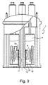
- the FIG. 3 shows a third embodiment of a cryostat 1 according to the invention.
- the HTS section 4 is connected to another thermal contact 31.
- This thermal contact 31 is guided through the bottom 32 of the helium tank 9 and connected to the radiation shield 12 in the bottom region thereof.
- the radiation shield 12 has a temperature T S of about 40 K and thus can deliver sufficient heat to the HTS section 4 to prevent ingress of superfluid helium in the HTS section 4.
- the heat input can be easily adjusted, for example, via the diameter of the thermal contact 31.
- the thermal contact 31 is preferably thermally insulated over its entire length to the ends, for example by a plastic jacket.
- means 33 are provided at the upper edge of the HTS section 4, which prevent helium between the thermal contact 31 and the wall 11 of the helium tank 9 can flow.
- the means 33 are annular for this purpose.
- the function of the means can also be taken over by the thermal contact 31 itself, or the HTS section 4 is sufficiently close to the wall 11, so that no convection can occur.
- FIG. 4 shows a fourth embodiment of a cryostat 1 according to the invention.
- the HTS section 4 is not actively (only) actively heated via thermal contacts but via an electric heater 41.
- run heating coil for example made of copper
- the heating power is chosen so that the desired temperature T H of the HTS section 4 results.
- a temperature sensor may be provided on or in the HTS section 4 in order to control T H. In general, a constant heating current is used.
- the electrical leads and the power supply of the electric heater 41 are not shown.
- the HTS section 4 is additionally surrounded by a sheath 42 of three-layered epoxy resin, which thermally isolates the HTS section 4 from the surrounding liquid helium and also mechanically separates it.
- the jacket 42 also includes the joint 7a, so that all HTS material is enclosed by the jacket 42. In the area of the joint 7a, an additional heating coil is provided.
- the cryostat 1 of the FIGS. 1 to 4 are preferably parts of an NMR apparatus, such as an NMR spectrometer or an NMR tomograph, in particular a high-resolution high-field NMR spectrometer with a magnetic field B 0 > 20 T, preferably> 23 T in the measurement volume, the magnetic coil system with respect to the homogeneity the magnetic field B 0 in the measurement volume and the time stability of B 0 meets the requirements of high-resolution NMR spectroscopy, which usually requires that the coil sections of the magnetic coil system can be superconductingly short-circuited during operation.
- an NMR apparatus such as an NMR spectrometer or an NMR tomograph
Landscapes
- Engineering & Computer Science (AREA)
- Power Engineering (AREA)
- Containers, Films, And Cooling For Superconductive Devices (AREA)
Claims (14)
- Cryostat (1),
muni d'un système de bobines magnétiques comprenant des conducteurs supraconducteurs en vue de générer un champ magnétique B0 dans un volume de mesure (3),
de plusieurs sections de bobines (4, 5, 6) en forme de solénoïdes emboîtées radialement les unes dans les autres, connectées électriquement en série, parmi lesquelles au moins une section LTS (5, 6) comprend un supraconducteur à basse température conventionnel (LTS) et au moins une section HTS (4) un supraconducteur à haute température (HTS),
le système de bobines magnétiques se trouvant avec de l'hélium liquide dans un réservoir d'hélium (9) du cryostat (1) à une température d'hélium TL < 4 K,
caractérisé en ce
qu'il est prévu des moyens de chauffage qui maintiennent le HTS à tout moment à une température augmentée TH > TL ainsi que TH > 2,2 K. - Cryostat (1) selon la revendication 1, caractérisé en ce que les moyens de chauffage maintiennent le HTS à tout moment à une température augmentée TH > 2,5 K.
- Cryostat (1) selon l'une des revendications précédentes, caractérisé en ce que la section HTS (4) forme la section (4) la plus intérieure radialement.
- Cryostat (1) selon l'une des revendications précédentes, caractérisé en ce que le cryostat (1) présente un alésage à température ambiante (2) entouré par le système de bobines magnétiques, dans lequel se trouve le volume de mesure (3).
- Cryostat selon la revendication 3 et 4, caractérisé en ce qu'il existe en tant que moyen de chauffage un contact thermique (10) entre la section (4) la plus intérieure et la paroi (11) du réservoir d'hélium (9) tournée vers l'alésage à température ambiante (2), le contact (10) transmettant le rayonnement thermique irradié sur cette paroi (11).
- Cryostat (1) selon l'une des revendications précédentes, caractérisé en ce qu'il existe en tant que moyen de chauffage un contact thermique (31) entre la section HTS (4) et un écran anti-rayonnement (12), l'écran anti-rayonnement (12) se trouvant à une température TS > TL, TS étant en particulier approximativement égale à 40 K.
- Cryostat (1) selon l'une des revendications précédentes, caractérisé en ce que les moyens de chauffage comprennent un chauffage électrique (41).
- Cryostat (1) selon l'une des revendications précédentes, caractérisé en ce que la section HTS (4) et le cas échéant aussi le contact thermique (10, 31) présentent une enveloppe (42) pour l'isolation thermique par rapport à l'hélium environnant.
- Cryostat (1) selon la revendication 8, caractérisé en ce que l'enveloppe (42) s'étend aussi sur des conduites d'amenée supraconductrices à la section HTS (4), et cela au moins aussi loin que les conduites d'amenée contiennent du HTS.
- Cryostat (1) selon l'une des revendications 8 ou 9, caractérisé en ce que l'enveloppe (42) est constituée en matière plastique, en particulier par une résine époxy multicouche.
- Cryostat (1) selon l'une des revendications précédentes, caractérisé en ce que le champ magnétique B0 généré par le système de bobines magnétiques dans le volume de mesure (3) est supérieur à 20 T, en particulier supérieur à 23 T.
- Cryostat (1) selon l'une des revendications précédentes, caractérisé en ce que les sections de bobines (4, 5, 6) du système de bobines magnétiques peuvent être court-circuitées de manière supraconductrice en fonctionnement.
- Cryostat (1) selon la revendication 12, caractérisé en ce que le système de bobines magnétiques satisfait aux exigences de la spectroscopie RMN à haute résolution en ce qui concerne l'homogénéité du champ magnétique B0 dans le volume de mesure et la stabilité dans le temps de B0.
- Cryostat (1) selon l'une des revendications précédentes, caractérisé en ce qu'il est prévu dans le réservoir d'hélium (9) des moyens (33) qui minimalisent une convection d'hélium autour de la section HTS (4).
Applications Claiming Priority (2)
| Application Number | Priority Date | Filing Date | Title |
|---|---|---|---|
| DE102006012506A DE102006012506A1 (de) | 2006-03-18 | 2006-03-18 | Kryostat mit einem Magnetspulensystem, das eine LTS- und eine beheizbare HTS-Sektion umfasst |
| PCT/EP2007/001927 WO2007107241A1 (fr) | 2006-03-18 | 2007-03-07 | Cryostat muni d'un système de bobines magnétiques qui comprend une section LTS et une section HTS chauffante |
Publications (2)
| Publication Number | Publication Date |
|---|---|
| EP2005447A1 EP2005447A1 (fr) | 2008-12-24 |
| EP2005447B1 true EP2005447B1 (fr) | 2009-10-28 |
Family
ID=38016709
Family Applications (1)
| Application Number | Title | Priority Date | Filing Date |
|---|---|---|---|
| EP07723072A Not-in-force EP2005447B1 (fr) | 2006-03-18 | 2007-03-07 | Cryostat muni d'un systeme de bobines magnetiques qui comprend une section lts et une section hts chauffante |
Country Status (4)
| Country | Link |
|---|---|
| US (1) | US8406833B2 (fr) |
| EP (1) | EP2005447B1 (fr) |
| DE (2) | DE102006012506A1 (fr) |
| WO (1) | WO2007107241A1 (fr) |
Families Citing this family (3)
| Publication number | Priority date | Publication date | Assignee | Title |
|---|---|---|---|---|
| CN101889213A (zh) * | 2007-12-10 | 2010-11-17 | 皇家飞利浦电子股份有限公司 | 具有冷却系统的超导磁体系统 |
| DE102014214796A1 (de) * | 2014-07-28 | 2016-01-28 | Bruker Biospin Ag | Verfahren zum Laden einer supraleitfähigen Magnetanordnung mit Strom |
| DE102019209160B3 (de) | 2019-06-25 | 2020-10-08 | Bruker Switzerland Ag | Kryostatanordnung mit federndem, wärmeleitendem Verbindungselement |
Family Cites Families (7)
| Publication number | Priority date | Publication date | Assignee | Title |
|---|---|---|---|---|
| US4924198A (en) * | 1988-07-05 | 1990-05-08 | General Electric Company | Superconductive magnetic resonance magnet without cryogens |
| GB8920345D0 (en) * | 1989-09-08 | 1989-10-25 | Oxford Advanced Tech | Magnetic field generating system |
| GB2247942B (en) * | 1990-09-05 | 1994-08-03 | Mitsubishi Electric Corp | Cryostat |
| JP2002008917A (ja) * | 2000-06-26 | 2002-01-11 | Inst Of Physical & Chemical Res | 超伝導体磁場応用装置の制御方法とこの方法を用いた核磁気共鳴装置と超伝導磁石装置 |
| DE10125429B4 (de) * | 2001-05-25 | 2004-06-17 | Bruker Biospin Gmbh | Supraleitfähige Höchstfeldmagnetspule mit HTS-Spulensektion und Herstellungsverfahren |
| NO20015691A (no) * | 2001-11-21 | 2002-10-28 | Sintef Energiforskning As | Superledende spoleanordning |
| DE102004007340B4 (de) * | 2004-02-16 | 2008-10-16 | Bruker Biospin Gmbh | Driftarmes supraleitendes Hochfeldmagnetsystem und hochauflösendes magnetisches Resonanzspektrometer |
-
2006
- 2006-03-18 DE DE102006012506A patent/DE102006012506A1/de not_active Withdrawn
-
2007
- 2007-03-07 WO PCT/EP2007/001927 patent/WO2007107241A1/fr active Application Filing
- 2007-03-07 DE DE502007001861T patent/DE502007001861D1/de active Active
- 2007-03-07 US US12/225,187 patent/US8406833B2/en not_active Expired - Fee Related
- 2007-03-07 EP EP07723072A patent/EP2005447B1/fr not_active Not-in-force
Also Published As
| Publication number | Publication date |
|---|---|
| EP2005447A1 (fr) | 2008-12-24 |
| DE502007001861D1 (de) | 2009-12-10 |
| WO2007107241A1 (fr) | 2007-09-27 |
| US20090275477A1 (en) | 2009-11-05 |
| DE102006012506A1 (de) | 2007-09-20 |
| US8406833B2 (en) | 2013-03-26 |
Similar Documents
| Publication | Publication Date | Title |
|---|---|---|
| EP1997116B1 (fr) | Cryostat muni d'un système de bobines magnétiques qui comprend une section lts et une section hts disposée dans la partie sous vide | |
| EP1999764B1 (fr) | Cryostat muni d'un systeme de bobines magnetiques qui comprend une section lts surrefroidie et une section hts disposee dans un reservoir d'helium separe | |
| EP2698794B1 (fr) | Agencement doté d'au moins un câble supraconducteur | |
| EP1738376B1 (fr) | Cable supraconducteur et son procede de production | |
| DE102006012508B3 (de) | Kryostat mit einem Magnetspulensystem, das eine LTS- und eine gekapselte HTS-Sektion umfasst | |
| DE69333128T2 (de) | Stromzuleitung für supraleitendes Magnetsystem ohne flüssiges Helium | |
| DE602004006913T2 (de) | Supraleitende RF-Spule für NMR-Apparatur | |
| EP2685469B1 (fr) | Agencement doté d'au moins un câble supraconducteur | |
| EP3281211B1 (fr) | Dispositif de transmission de courant continu | |
| DE102013220142A1 (de) | Magnetspulenanordnung umfassend einen HTSL-Bandleiter und einen LTS-Draht, die einen Joint ausbilden | |
| EP0154779A1 (fr) | Système supraconducteur magnétique pour le fonctionnement à 13K | |
| EP2426676A1 (fr) | Agencement doté d'au moins un câble supraconducteur | |
| EP2005447B1 (fr) | Cryostat muni d'un systeme de bobines magnetiques qui comprend une section lts et une section hts chauffante | |
| DE102004058006B3 (de) | Supraleitungseinrichtung mit Kryosystem und supraleitendem Schalter | |
| DE3811051C2 (fr) | ||
| EP3696559A1 (fr) | Tête de sonde mas à chambre à échantillons thermiquement isolée | |
| EP0485395A1 (fr) | Bobine magnetique supraconductrice homogene a champ eleve. | |
| EP1774601A1 (fr) | Element supraconducteur a renforcement | |
| EP0082409B1 (fr) | Procédé thermique pour faire transiter rapidement une bobine supraconductrice de l'état supraconducteur à l'état normal, et dispositif pour exécuter le procédé | |
| DE2163270B1 (de) | Stromzuführung fur elektrische Ein richtungen mit auf Tieftemperatur ge kühlten Leitern | |
| WO2016083203A1 (fr) | Dispositif de supraconductivité présentant des dispositifs de bobinage et un dispositif de refroidissement, ainsi que véhicule équipé de celui-ci | |
| EP3467852A1 (fr) | Dispositif magnétique pourvu de cryostat et de système de bobines magnétiques, d'accumulateurs de froid sur les alimentations en courant | |
| WO2015193163A1 (fr) | Alimentation en courant pour système de bobine supraconductrice | |
| WO1993004487A1 (fr) | Alimentation en courant a basse temperature avec echangeur de chaleur | |
| EP3503329B1 (fr) | Procédé de refroidissement d'un système de câblage supraconducteur |
Legal Events
| Date | Code | Title | Description |
|---|---|---|---|
| PUAI | Public reference made under article 153(3) epc to a published international application that has entered the european phase |
Free format text: ORIGINAL CODE: 0009012 |
|
| 17P | Request for examination filed |
Effective date: 20081020 |
|
| AK | Designated contracting states |
Kind code of ref document: A1 Designated state(s): CH DE FR GB LI |
|
| DAX | Request for extension of the european patent (deleted) | ||
| RBV | Designated contracting states (corrected) |
Designated state(s): CH DE FR GB LI |
|
| GRAP | Despatch of communication of intention to grant a patent |
Free format text: ORIGINAL CODE: EPIDOSNIGR1 |
|
| GRAS | Grant fee paid |
Free format text: ORIGINAL CODE: EPIDOSNIGR3 |
|
| GRAA | (expected) grant |
Free format text: ORIGINAL CODE: 0009210 |
|
| AK | Designated contracting states |
Kind code of ref document: B1 Designated state(s): CH DE FR GB LI |
|
| REG | Reference to a national code |
Ref country code: GB Ref legal event code: FG4D Free format text: NOT ENGLISH |
|
| REG | Reference to a national code |
Ref country code: CH Ref legal event code: EP |
|
| REF | Corresponds to: |
Ref document number: 502007001861 Country of ref document: DE Date of ref document: 20091210 Kind code of ref document: P |
|
| PLBE | No opposition filed within time limit |
Free format text: ORIGINAL CODE: 0009261 |
|
| STAA | Information on the status of an ep patent application or granted ep patent |
Free format text: STATUS: NO OPPOSITION FILED WITHIN TIME LIMIT |
|
| 26N | No opposition filed |
Effective date: 20100729 |
|
| REG | Reference to a national code |
Ref country code: FR Ref legal event code: PLFP Year of fee payment: 10 |
|
| REG | Reference to a national code |
Ref country code: FR Ref legal event code: PLFP Year of fee payment: 11 |
|
| REG | Reference to a national code |
Ref country code: FR Ref legal event code: PLFP Year of fee payment: 12 |
|
| PGFP | Annual fee paid to national office [announced via postgrant information from national office to epo] |
Ref country code: DE Payment date: 20200324 Year of fee payment: 14 Ref country code: GB Payment date: 20200325 Year of fee payment: 14 |
|
| PGFP | Annual fee paid to national office [announced via postgrant information from national office to epo] |
Ref country code: CH Payment date: 20200325 Year of fee payment: 14 |
|
| PGFP | Annual fee paid to national office [announced via postgrant information from national office to epo] |
Ref country code: FR Payment date: 20200325 Year of fee payment: 14 |
|
| REG | Reference to a national code |
Ref country code: DE Ref legal event code: R119 Ref document number: 502007001861 Country of ref document: DE |
|
| REG | Reference to a national code |
Ref country code: CH Ref legal event code: PL |
|
| GBPC | Gb: european patent ceased through non-payment of renewal fee |
Effective date: 20210307 |
|
| PG25 | Lapsed in a contracting state [announced via postgrant information from national office to epo] |
Ref country code: CH Free format text: LAPSE BECAUSE OF NON-PAYMENT OF DUE FEES Effective date: 20210331 Ref country code: LI Free format text: LAPSE BECAUSE OF NON-PAYMENT OF DUE FEES Effective date: 20210331 Ref country code: GB Free format text: LAPSE BECAUSE OF NON-PAYMENT OF DUE FEES Effective date: 20210307 Ref country code: FR Free format text: LAPSE BECAUSE OF NON-PAYMENT OF DUE FEES Effective date: 20210331 Ref country code: DE Free format text: LAPSE BECAUSE OF NON-PAYMENT OF DUE FEES Effective date: 20211001 |