EP2005447B1 - Cryostat having a magnet coil system, which comprises an lts section and a heatable hts section - Google Patents
Cryostat having a magnet coil system, which comprises an lts section and a heatable hts section Download PDFInfo
- Publication number
- EP2005447B1 EP2005447B1 EP07723072A EP07723072A EP2005447B1 EP 2005447 B1 EP2005447 B1 EP 2005447B1 EP 07723072 A EP07723072 A EP 07723072A EP 07723072 A EP07723072 A EP 07723072A EP 2005447 B1 EP2005447 B1 EP 2005447B1
- Authority
- EP
- European Patent Office
- Prior art keywords
- cryostat
- hts
- section
- helium
- coil system
- Prior art date
- Legal status (The legal status is an assumption and is not a legal conclusion. Google has not performed a legal analysis and makes no representation as to the accuracy of the status listed.)
- Not-in-force
Links
Images


Classifications
-
- H—ELECTRICITY
- H01—ELECTRIC ELEMENTS
- H01F—MAGNETS; INDUCTANCES; TRANSFORMERS; SELECTION OF MATERIALS FOR THEIR MAGNETIC PROPERTIES
- H01F6/00—Superconducting magnets; Superconducting coils
- H01F6/04—Cooling
Definitions
- the invention relates to a cryostat having a magnetic coil system comprising a superconductive conductor for generating a magnetic field B 0 in a measuring volume with a plurality of radially nested, electrically connected coil sections, of which at least one LTS section comprises a conventional low temperature superconductor (LTS). and at least one HTS section comprises a high temperature superconductor (HTS), wherein the liquid helium magnetic levitation system is in a helium tank of the cryostat at a helium temperature T L ⁇ 4K.
- LTS low temperature superconductor
- HTS high temperature superconductor
- cryostat has become known, for example from the DE 10 2004 007 340 A1 .
- LTS low-temperature superconductors
- NbTi and Nb 3 Sn are relatively easy to process and reliable in use.
- the conductor of an LTS coil section usually consists of a good normal conductive metallic matrix (copper), in which superconducting filaments are located, which completely take over the current during normal operation.
- NbTi these are usually tens to hundreds, in the case of Nb 3 Sn, it may be more than a hundred thousand.
- the inner structure of the ladder is a bit more complex, but this does not matter in the present context.
- the coil sections are cooled with liquid helium in a cryostat.
- the superconducting coil sections dip at least partially into liquid helium.
- HTS high-temperature superconductors
- HTS or ceramic superconductors are mainly available as bismuth conductors with HTS filaments in a silver-containing matrix.
- the ladders are predominantly in the form of ribbons.
- cryostat of the type described above, which is characterized in that heating means are provided which keep the HTS at any time at an elevated temperature T H > T L and T H > 2.2 K.
- the present invention is based on the finding that the "ballooning" is caused by superfluid helium, which expands or evaporates in the interior of the HTS material.
- helium liquefies at atmospheric pressure below about 4.2 K.
- Helium continues to exhibit a phase transition of the second kind ( ⁇ point) at a temperature of 2.2 K.
- ⁇ point phase transition of the second kind
- liquid helium becomes superfluous, ie the helium can flow without friction and has an infinitely high thermal conductivity.
- the former effect ensures that it penetrates even the smallest gaps, especially in spite of the sheathing through the matrix in the cavities inside a ceramic HTS. In contrast, a compression of the ceramic material helps nothing.
- the HTS is maintained by the heating means according to the invention at a temperature at which superfluid helium does not occur. This ensures that no superfluid helium penetrates into the HTS. This can not come to the "ballooning".
- the temperature T L of most of the liquid helium in the helium tank of the cryostat can be equal to or lower than the ⁇ -point temperature of 2.2 K according to the invention.
- the HTS only needs to be kept warm enough locally.
- a temperature T L of 2.2 K or below is favorable even for particularly stable conditions for the LTS sections, in particular, mechanical deformations due to temperature differences are minimized. But above all, a T L ⁇ 2.2 K increases the current carrying capacity and the critical magnetic field strength in the co-cooled LTS sections.
- a preferred embodiment of the cryostat according to the invention provides that the heating means keep the HTS at an elevated temperature T H > 2.5 K at all times. Even above the ⁇ -point temperature of 2.2 K, superfluid helium phase can briefly occur. With this embodiment, a sufficient buffer is set up against such fluctuations and the HTS is even better protected.
- the HTS section forms the radially innermost section.
- the largest magnetic field strengths and the expensive and problematic HTS is used particularly effectively. Furthermore, this arrangement facilitates only local cooling of the HTS section.
- cryostat has a room temperature bore surrounded by the magnetic coil system, in which the measurement volume is located, is preferred.
- the room temperature hole allows easy placement of a sample at room or variable temperature in the measurement volume.
- a preferred development of this embodiment provides that there is a thermal contact between the innermost section and the wall of the helium tank facing the room temperature bore, wherein the contact forwards radiated heat radiation to this wall.
- This passive heating of the HTS section is particularly reliable, since a sufficient temperature for heating the HTS section on the design of radiation shields and the mechanical coupling to the wall of the helium tank and possibly the prevention of convection in the helium tank to the HTS section easy to ensure around. In particular, the passive heating makes a power failure for the HTS harmless.
- Another advantageous embodiment provides that there is a thermal contact between the HTS section through the wall of the helium tank to a radiation shield as a heating means, wherein the radiation shield is at a temperature T S > T L , in particular wherein T S is about 40 K. , This heating is passive and thus energy saving. Again, a power failure in particular for the HTS is safe.
- the heating means comprise an electric heater.
- the electric heater is easy to control and allows accurate temperature control of the HTS section even outside normal operating conditions, especially when filling or emptying the helium tank or when quenching.
- cryostat which provides that the HTS section and possibly also the thermal contact has a jacket for thermal insulation against the surrounding helium.
- This embodiment reduces the necessary cooling power for the liquid helium in the cryostat, which compensates for the heat input of the heating means.
- the HTS is also mechanically protected against superfluid helium.
- the sheath also extends to superconducting leads to the HTS section, at least as far as the leads HTS included. This also includes the joints in the protection against penetrating superfluid helium.
- sheath is formed of plastic, in particular by a multilayer epoxy resin.
- a preferred embodiment provides that the magnetic field B 0 generated in the measurement volume by the magnet coil system is greater than 20 T, in particular greater than 23 T. These strong magnetic fields are easily accessible by means of HTS section and the cryostat according to the invention. In contrast, with conventional magnet systems based only on LTS sections, the theoretical limit is already reached at these field strengths, and the critical current density tends toward zero.
- the coil sections of the magnet coil system can be superconductingly short-circuited during operation.
- NMR and ICR Ion cyclotron resonance
- an embodiment which is characterized in that the magnetic coil system with respect to the homogeneity of the magnetic field B 0 in the measurement volume and the time stability of B 0 meets the requirements of high-resolution NMR spectroscopy, which requires a special design of the magnetic coil system and the cryostat which is known per se for pure LTS systems.
- cryostat according to the invention which provides that means are provided in the helium tank for minimizing convection of helium around the HTS section.
- These means are, for example, mechanical barriers located on or near the surface of the HTS section and obstructing the helium flows on the surface of the HTS section or on the surface of parts that are thermally coupled to the HTS section.
- the reduced convection reduces heat input by the heating means into the liquid helium, and conversely reduces the cooling efficiency of the liquid helium at the HTS section.
- the cryostat is more economical and stable to operate.
- the FIG. 1 schematically shows a first embodiment of a cryostat 1 according to the invention.
- the cryostat 1 has a room temperature bore 2, in which an examination volume 3 is provided for a sample.
- the examination volume is located in the center of a magnetic coil system which is formed from here three solenoid-shaped coil sections 4, 5, 6.
- the magnet coil system generates a homogeneous magnetic field B 0 in the examination volume 3.
- the middle coil section 5 is wound with Nb 3 Sn wire and the outermost coil section 6 is wound with NbTi wire.
- the coil sections 4, 5, 6 are electrically connected in series with one another, by way of example with the two superconducting transition points (joints) 7a and 7b.
- the HTS material of the HTS section 4 is connected to an NbTi transition piece 8
- the transition piece 8 is connected to the Nb 3 Sn wire of the LTS section 5.
- the coil sections 4, 5, 6 are located inside a helium tank 9, which is largely filled with liquid helium.
- the liquid helium in the helium tank 9 has a temperature T L of less than 4 K, for example about 2.0 K.
- the helium in the helium tank 9 is constantly cooled by a cooling device, not shown, to compensate for heat input from the outside and to keep T L constant , see eg US 5,220,800 .
- a cooling device not shown
- the helium tank like in the US 5,220,800 have two chambers separated by a thermal barrier, which are at temperatures of about 2 K and 4 K, wherein the magnetic coil system is disposed in the 2 K chamber.
- the LTS coil sections 5, 6 located in this helium bath have likewise assumed the temperature T L.
- the situation is different with the HTS coil section 4.
- This has a thermal contact 10, which connects the HTS section 4 with the wall 11 of the helium tank 9, which faces the room temperature bore 2 (and the examination volume 3), heat-conducting.
- Thermal radiation which impinges on the wall 11 then provides heat input via the thermal contact 10 into the HTS section 4.
- This heat radiation can be emitted, for example, from the radiation shield 12 surrounding the helium tank 9.
- the radiation shield 12 in particular undergoes heat radiation from the wall of the room temperature bore 2.
- the radiation shield 12 has a temperature of approximately 40 K.
- T H which is greater than T L , and according to the invention also greater than the temperature of the ⁇ point of FIG. 4, arises at the HTS section 4 He is about 2.2K.
- T H is about 3.0 K. This value of T H is sufficient to prevent ingress of superfluid helium into the HTS section and into the HTS itself, ie helium remains in the area of the surface of the HTS section 4 normal liquid and can not penetrate deeper.
- FIG. 2 shows a slightly modified embodiment of the cryostat 1. If the heat input by radiant heat to the wall 11 and thus in the thermal contact 10 should not be sufficient to sufficiently heat the HTS section 4, contact fields 21 may be provided. These contact springs 21 connect a relatively warm part of the cryostat 1 (warmer than T L and warmer than 2.2 K), namely here the radiation shield 12 (with T S about 40 K), with the wall eleventh
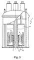
- the FIG. 3 shows a third embodiment of a cryostat 1 according to the invention.
- the HTS section 4 is connected to another thermal contact 31.
- This thermal contact 31 is guided through the bottom 32 of the helium tank 9 and connected to the radiation shield 12 in the bottom region thereof.
- the radiation shield 12 has a temperature T S of about 40 K and thus can deliver sufficient heat to the HTS section 4 to prevent ingress of superfluid helium in the HTS section 4.
- the heat input can be easily adjusted, for example, via the diameter of the thermal contact 31.
- the thermal contact 31 is preferably thermally insulated over its entire length to the ends, for example by a plastic jacket.
- means 33 are provided at the upper edge of the HTS section 4, which prevent helium between the thermal contact 31 and the wall 11 of the helium tank 9 can flow.
- the means 33 are annular for this purpose.
- the function of the means can also be taken over by the thermal contact 31 itself, or the HTS section 4 is sufficiently close to the wall 11, so that no convection can occur.
- FIG. 4 shows a fourth embodiment of a cryostat 1 according to the invention.
- the HTS section 4 is not actively (only) actively heated via thermal contacts but via an electric heater 41.
- run heating coil for example made of copper
- the heating power is chosen so that the desired temperature T H of the HTS section 4 results.
- a temperature sensor may be provided on or in the HTS section 4 in order to control T H. In general, a constant heating current is used.
- the electrical leads and the power supply of the electric heater 41 are not shown.
- the HTS section 4 is additionally surrounded by a sheath 42 of three-layered epoxy resin, which thermally isolates the HTS section 4 from the surrounding liquid helium and also mechanically separates it.
- the jacket 42 also includes the joint 7a, so that all HTS material is enclosed by the jacket 42. In the area of the joint 7a, an additional heating coil is provided.
- the cryostat 1 of the FIGS. 1 to 4 are preferably parts of an NMR apparatus, such as an NMR spectrometer or an NMR tomograph, in particular a high-resolution high-field NMR spectrometer with a magnetic field B 0 > 20 T, preferably> 23 T in the measurement volume, the magnetic coil system with respect to the homogeneity the magnetic field B 0 in the measurement volume and the time stability of B 0 meets the requirements of high-resolution NMR spectroscopy, which usually requires that the coil sections of the magnetic coil system can be superconductingly short-circuited during operation.
- an NMR apparatus such as an NMR spectrometer or an NMR tomograph
Description
Die Erfindung betrifft einen Kryostaten, mit einem supraleitfähige Leiter umfassenden Magnetspulensystem zur Erzeugung eines Magnetfelds B0 in einem Messvolumen mit mehreren, radial ineinander geschachtelt angeordneten, elektrisch in Serie geschalteten, solenoidförmigen Spulensektionen, von denen mindesten eine LTS-Sektion einen konventionellen Tieftemperatursupraleiter (LTS) und mindestens eine HTS-Sektion einen Hochtemperatursupraleiter (HTS) umfasst, wobei sich das Magnetsputensystem mit flüssigem Helium in einem Heliumtank des Kryostaten bei einer Helium-Temperatur TL < 4 K befindet.The invention relates to a cryostat having a magnetic coil system comprising a superconductive conductor for generating a magnetic field B 0 in a measuring volume with a plurality of radially nested, electrically connected coil sections, of which at least one LTS section comprises a conventional low temperature superconductor (LTS). and at least one HTS section comprises a high temperature superconductor (HTS), wherein the liquid helium magnetic levitation system is in a helium tank of the cryostat at a helium temperature T L <4K.
Ein solcher Kryostat ist beispielsweise bekannt geworden aus der
Zum Beispiel für Kernspinresonanz-Apparaturen, insbesondere Spektrometer, werden sehr starke, homogene und stabile Magnetfelder benötigt. Je stärker das Magnetfeld, desto besser ist das Signal-zu-Rausch-Verhältnis und die spektrale Auflösung der NMR-Messung.For example, for nuclear magnetic resonance apparatus, in particular spectrometers, very strong, homogeneous and stable magnetic fields are needed. The stronger the magnetic field, the better the signal-to-noise ratio and the spectral resolution of the NMR measurement.
Zur Erzeugung starker Magnetfelder werden supraleitende Magnetspulensysteme eingesetzt. Weit verbreitet sind Magnetspulensysteme mit solenoidförmigen Spulensektionen, die ineinander geschachtelt sind und in Serie betrieben werden. Supraleiter können elektrischen Strom verlustfrei tragen. Die Supraleitung stellt sich unterhalb einer materialabhängigen Sprungtemperatur ein. Als Supraleitermaterial werden typischerweise konventionelle Tieftemperatur-Supraleiter (LTS) eingesetzt. Diese Metalllegierungen wie beispielsweise NbTi und Nb3Sn sind verhältnismäßig leicht zu verarbeiten und zuverlässig in der Anwendung. Der Leiter einer LTS-Spulensektion besteht in der Regel aus einer gut normalleitenden metallischen Matrix (Kupfer), in der sich supraleitende Filamente befinden, die im Normalbetrieb vollständig den Strom übernehmen. Im Fall von NbTi sind das üblicherweise einige zehn bis hundert, im Fall von Nb3Sn können es mehr als hunderttausend sein. Tatsächlich ist der innere Aufbau der Leiter noch etwas komplexer, was aber im vorliegenden Zusammenhang keine Rolle spielt.To generate strong magnetic fields, superconducting magnet coil systems are used. Magnetic coil systems with solenoid-shaped coil sections, which are nested in one another and are operated in series, are widespread. Superconductors can carry electrical power without loss. The superconductivity sets itself below a material-dependent transition temperature. Conventional low-temperature superconductors (LTS) are typically used as the superconductor material. These metal alloys such as NbTi and Nb 3 Sn are relatively easy to process and reliable in use. The conductor of an LTS coil section usually consists of a good normal conductive metallic matrix (copper), in which superconducting filaments are located, which completely take over the current during normal operation. In the case of NbTi, these are usually tens to hundreds, in the case of Nb 3 Sn, it may be more than a hundred thousand. In fact, the inner structure of the ladder is a bit more complex, but this does not matter in the present context.
Um die Spulensektionen unter die Sprungtemperatur abzukühlen, werden die Spulensektionen mit flüssigem Helium in einem Kryostaten gekühlt. Die supraleitenden Spulensektionen tauchen dabei zumindest teilweise in flüssiges Helium ein.To cool the coil sections below the critical temperature, the coil sections are cooled with liquid helium in a cryostat. The superconducting coil sections dip at least partially into liquid helium.
Um die erreichbare Magnetfeldstärke in einem Magnetspulensystem weiter zu steigern, ist es wünschenswert, auch Hochtemperatur-Supraleiter (HTS) einzusetzen. Bei gleicher Temperatur können Leiter, die HTS enthalten, sehr viel mehr Strom tragen und höhere Magnetfeldstärken erreichen als solche mit LTS. HTS-Material bietet sich somit vor allem als Material für die innersten Spulensektionen eines Magnetspulensystems an.In order to further increase the achievable magnetic field strength in a magnetic coil system, it is desirable to also use high-temperature superconductors (HTS). At the same temperature, conductors containing HTS can carry much more current and reach higher magnetic field strengths than those LTS. HTS material is therefore primarily suitable as material for the innermost coil sections of a magnetic coil system.
HTS oder auch keramische Supraleiter gibt es derzeit vor allem als Wismut-Leiter mit HTS-Filamenten in einer silberhaltigen Matrix. Die Leiter haben vorwiegend die Form von Bändchen.Currently, HTS or ceramic superconductors are mainly available as bismuth conductors with HTS filaments in a silver-containing matrix. The ladders are predominantly in the form of ribbons.
Spulensektionen aus HTS in unterkühltem Helium haben sich bisher allerdings als kurzlebig und unzuverlässig erwiesen. Eine Untersuchung von ausgefallenen HTS-Sektionen hat ergeben, dass das HTS-Material aufplatzt und die Stromtragfähigkeit des HTS-Leiters damit zerstört wird. Dieser an sich auch in anderen Zusammenhängen bekannte Effekt wird gelegentlich als "ballooning" bezeichnet.Coil sections made of HTS in supercooled helium have, however, proven to be short-lived and unreliable. An investigation of failed HTS sections revealed that the HTS material bursts and the current carrying capacity of the HTS conductor is thereby destroyed. This effect, which is also known in other contexts, is sometimes referred to as "ballooning".
Demnach ist es die Aufgabe der vorliegenden Erfindung, einen Kryostaten bereitzustellen, in dem eine HTS-Spulensektion langfristig und zuverlässig eingesetzt werden kann, und insbesondere kein "ballooning" auftritt.Accordingly, it is the object of the present invention to provide a cryostat in which a HTS coil section can be used long-term and reliable, and in particular no "ballooning" occurs.
Diese Aufgabe wird gelöst durch einen Kryostaten der eingangs vorgestellten Art, der dadurch gekennzeichnet ist, dass Heizmittel vorgesehen sind, die den HTS jederzeit auf einer erhöhten Temperatur TH > TL sowie TH > 2,2 K halten.This object is achieved by a cryostat of the type described above, which is characterized in that heating means are provided which keep the HTS at any time at an elevated temperature T H > T L and T H > 2.2 K.
Der vorliegenden Erfindung liegt die Erkenntnis zugrunde, dass das "ballooning" durch superflüssiges Helium verursacht wird, das im Inneren des HTS-Materials expandiert oder verdampft. Bekanntermaßen verflüssigt sich Helium bei Normaldruck unterhalb von ca. 4,2 K. Helium zeigt aber weiterhin bei einer Temperatur von 2,2 K einen Phasenübergang 2. Art (λ-Punkt). Unterhalb des λ-Punkts wird flüssiges Helium superflüssig, d.h. das Helium kann reibungsfrei fließen und hat eine unendlich hohe Wärmeleitfähigkeit. Der erstere Effekt sorgt dafür, dass es auch in kleinste Spalten eindringt, insbesondere trotz der Ummantelung durch die Matrix auch in die Hohlräume im Inneren eines keramischen HTS. Dagegen hilft auch eine Verdichtung des Keramikmaterials nichts. Im Falle einer späteren Erwärmung über den λ-Punkt bleibt das Helium im HTS gefangen. Die Erwärmung sorgt aber auch für eine Expansion des gefangenen Heliums, insbesondere wenn die Erwärmung so stark ist, dass das Helium verdampft. Dadurch wird im Inneren des HTS ein erheblicher Druck aufgebaut. Da HTS ein keramisches und damit sprödes Material ist, wird der HTS schließlich lokal vom Druck gesprengt und der Leiter degradiert.The present invention is based on the finding that the "ballooning" is caused by superfluid helium, which expands or evaporates in the interior of the HTS material. As is known, helium liquefies at atmospheric pressure below about 4.2 K. Helium, however, continues to exhibit a phase transition of the second kind (λ point) at a temperature of 2.2 K. Below the λ point, liquid helium becomes superfluous, ie the helium can flow without friction and has an infinitely high thermal conductivity. Of the the former effect ensures that it penetrates even the smallest gaps, especially in spite of the sheathing through the matrix in the cavities inside a ceramic HTS. In contrast, a compression of the ceramic material helps nothing. In case of a later warming over the λ-point the helium remains trapped in the HTS. The warming also ensures an expansion of the trapped helium, especially if the warming is so strong that the helium evaporates. As a result, a considerable pressure is built up inside the HTS. Since HTS is a ceramic and thus brittle material, the HTS is finally burst locally from the pressure and degrades the conductor.
Dies kann durch den erfindungsgemäßen Kryostaten verhindert werden. Der HTS wird durch die erfindungsgemäßen Heizmittel auf einer Temperatur gehalten, bei der superflüssiges Helium nicht auftritt. Dadurch ist sichergestellt, dass auch kein superflüssiges Helium in den HTS eindringt. Damit kann es nicht zum "ballooning" kommen.This can be prevented by the cryostat according to the invention. The HTS is maintained by the heating means according to the invention at a temperature at which superfluid helium does not occur. This ensures that no superfluid helium penetrates into the HTS. This can not come to the "ballooning".
Man beachte, dass die Temperatur TL des größten Teils des flüssigen Heliums im Heliumtank des Kryostaten dabei erfindungsgemäß durchaus gleich oder niedriger als die λ-Punkt-Temperatur von 2,2 K sein kann. Der HTS braucht lediglich lokal ausreichend warm gehalten zu werden. Eine Temperatur TL von 2,2 K oder darunter ist sogar wegen besonders stabiler Verhältnisse für die LTS-Sektionen günstig, insbesondere sind mechanische Verformungen aufgrund von Temperaturdifferenzen minimiert. Aber vor allem erhöht ein TL < 2,2 K die Stromtragfähigkeit und die kritische Magnetfeldstärke bei den mitgekühlten LTS-Sektionen.It should be noted that the temperature T L of most of the liquid helium in the helium tank of the cryostat can be equal to or lower than the λ-point temperature of 2.2 K according to the invention. The HTS only needs to be kept warm enough locally. A temperature T L of 2.2 K or below is favorable even for particularly stable conditions for the LTS sections, in particular, mechanical deformations due to temperature differences are minimized. But above all, a T L <2.2 K increases the current carrying capacity and the critical magnetic field strength in the co-cooled LTS sections.
Eine bevorzugte Ausführungsform des erfindungsgemäßen Kryostaten sieht vor, dass die Heizmittel den HTS jederzeit auf einer erhöhten Temperatur TH > 2,5 K halten. Auch oberhalb der λ-Punkt-Temperatur von 2,2 K kann kurzzeitig superflüssige Heliumphase auftreten. Mit dieser Ausführungsform wird ein ausreichender Puffer gegen solche Fluktuationen eingerichtet und der HTS noch besser geschützt.A preferred embodiment of the cryostat according to the invention provides that the heating means keep the HTS at an elevated temperature T H > 2.5 K at all times. Even above the λ-point temperature of 2.2 K, superfluid helium phase can briefly occur. With this embodiment, a sufficient buffer is set up against such fluctuations and the HTS is even better protected.
Besonders bevorzugt ist auch eine Ausführungsform, bei der die HTS-Sektion die radial innerste Sektion bildet. Hier treten die größten Magnetfeldstärken auf, und der teure und problematische HTS ist besonders effektiv eingesetzt. Weiterhin erleichtert diese Anordnung die lediglich lokale Kühlung der HTS-Sektion.Particularly preferred is also an embodiment in which the HTS section forms the radially innermost section. Here are the largest magnetic field strengths, and the expensive and problematic HTS is used particularly effectively. Furthermore, this arrangement facilitates only local cooling of the HTS section.
Weiterhin ist bevorzugt eine Ausführungsform, bei der der Kryostat eine von dem Magnetspulensystem umgebene Raumtemperaturbohrung aufweist, in der sich das Messvolumen befindet. Die Raumtemperaturbohrung gestattet eine einfache Platzierung einer Probe bei Raum- oder variabler Temperatur im Messvolumen.Furthermore, an embodiment in which the cryostat has a room temperature bore surrounded by the magnetic coil system, in which the measurement volume is located, is preferred. The room temperature hole allows easy placement of a sample at room or variable temperature in the measurement volume.
Eine bevorzugte Weiterbildung dieser Ausführungsform sieht vor, dass als Heizmittel ein thermischer Kontakt zwischen der innersten Sektion und der der Raumtemperaturbohrung zugewandten Wand des Heliumtanks besteht, wobei der Kontakt auf diese Wand eingestrahlte Wärmestrahlung weiterleitet. Diese passive Beheizung der HTS-Sektion ist besonders zuverlässig, da eine für die Beheizung der HTS-Sektion ausreichende Temperatur über die Auslegung von Strahlungsschildern sowie der mechanischen Ankopplung an die Wand des Heliumtanks sowie ggf. der Unterbindung von Konvektion im Heliumtank um die HTS-Sektion herum leicht zu gewährleisten ist. Insbesondere ist durch die passive Beheizung ein Stromausfall für den HTS ungefährlich.A preferred development of this embodiment provides that there is a thermal contact between the innermost section and the wall of the helium tank facing the room temperature bore, wherein the contact forwards radiated heat radiation to this wall. This passive heating of the HTS section is particularly reliable, since a sufficient temperature for heating the HTS section on the design of radiation shields and the mechanical coupling to the wall of the helium tank and possibly the prevention of convection in the helium tank to the HTS section easy to ensure around. In particular, the passive heating makes a power failure for the HTS harmless.
Eine andere vorteilhafte Ausführungsform sieht vor, dass als Heizmittel ein thermischer Kontakt zwischen der HTS-Sektion durch die Wand des Heliumtanks zu einem Strahlungsschild besteht, wobei sich der Strahlungsschild auf einer Temperatur TS > TL befindet, insbesondere wobei TS ungefähr 40 K beträgt. Diese Beheizung ist passiv und somit energiesparend. Auch hier ist insbesondere ein Stromausfall für den HTS ungefährlich.Another advantageous embodiment provides that there is a thermal contact between the HTS section through the wall of the helium tank to a radiation shield as a heating means, wherein the radiation shield is at a temperature T S > T L , in particular wherein T S is about 40 K. , This heating is passive and thus energy saving. Again, a power failure in particular for the HTS is safe.
Vorteilhaft ist auch eine Ausführungsform, bei der die Heizmittel eine elektrische Heizung umfassen. Die elektrische Heizung ist leicht zu steuern und gestattet auch außerhalb des normalen Betriebszustands eine genaue Temperaturkontrolle der HTS-Sektion, insbesondere beim Befüllen oder Leeren des Heliumtanks bzw. im Quenchfall.Also advantageous is an embodiment in which the heating means comprise an electric heater. The electric heater is easy to control and allows accurate temperature control of the HTS section even outside normal operating conditions, especially when filling or emptying the helium tank or when quenching.
Besonders bevorzugt ist auch eine Ausführungsform des erfindungsgemäßen Kryostaten, die vorsieht, dass die HTS-Sektion und ggf. auch der thermische Kontakt eine Ummantelung zur thermischen Isolierung gegen das umgebende Helium aufweist. Diese Ausführungsform reduziert die notwendige Kühlleistung für das flüssige Helium im Kryostaten, die den Wärmeeintrag der Heizmittel ausgleicht. Weiterhin wird der HTS auch mechanisch vor superflüssigem Helium zusätzlich geschützt.Particularly preferred is also an embodiment of the cryostat according to the invention, which provides that the HTS section and possibly also the thermal contact has a jacket for thermal insulation against the surrounding helium. This embodiment reduces the necessary cooling power for the liquid helium in the cryostat, which compensates for the heat input of the heating means. Furthermore, the HTS is also mechanically protected against superfluid helium.
In einer bevorzugten Weiterbildung dieser Ausführungsform erstreckt die Ummantelung sich auch auf supraleitende Zuleitungen zur HTS-Sektion, und zwar mindestens so weit die Zuleitungen HTS enthalten. Damit sind auch die Joints in den Schutz vor eindringendem superflüssigem Helium einbezogen.In a preferred development of this embodiment, the sheath also extends to superconducting leads to the HTS section, at least as far as the leads HTS included. This also includes the joints in the protection against penetrating superfluid helium.
Eine weitere Weiterbildung sieht vor, dass die Ummantelung aus Kunststoff ausgebildet ist, insbesondere durch ein mehrschichtiges Epoxyharz.A further development provides that the sheath is formed of plastic, in particular by a multilayer epoxy resin.
Eine bevorzugte Ausführungsform sieht vor, dass das im Messvolumen durch das Magnetspulensystem erzeugte Magnetfeld B0 größer als 20 T, insbesondere größer als 23 T ist. Diese starken Magnetfelder sind mittels HTS-Sektion und dem erfindungsgemäßen Kryostaten gut erreichbar. Im Gegensatz dazu wird mit konventionellen Magnetsystemen, die nur auf LTS-Sektionen basieren, bei diesen Feldstärken schon die theoretische Grenze erreicht, und die kritische Stromdichte strebt gegen null.A preferred embodiment provides that the magnetic field B 0 generated in the measurement volume by the magnet coil system is greater than 20 T, in particular greater than 23 T. These strong magnetic fields are easily accessible by means of HTS section and the cryostat according to the invention. In contrast, with conventional magnet systems based only on LTS sections, the theoretical limit is already reached at these field strengths, and the critical current density tends toward zero.
Bevorzugt ist weiterhin eine Ausführungsform, bei der die Spulensektionen des Magnetspulensystems im Betrieb supraleitend kurzgeschlossen werden können. Dadurch wird die beispielsweise für NMR- und ICR (Ionenzyklotronresonanz) erforderliche Stabilität erreicht.Also preferred is an embodiment in which the coil sections of the magnet coil system can be superconductingly short-circuited during operation. As a result, for example, for NMR and ICR (Ion cyclotron resonance) required stability achieved.
Ebenfalls bevorzugt ist eine Ausführungsform, die dadurch gekennzeichnet ist, dass das Magnetspulensystem bezüglich der Homogenität des Magnetfelds B0 im Messvolumen und der zeitlichen Stabilität von B0 die Anforderungen der hochauflösenden NMR-Spektroskopie erfüllt, was eine spezielle Gestaltung des Magnetspulensystems und des Kryostaten erfordert, die für reine LTS-Systeme an sich bekannt ist.Also preferred is an embodiment, which is characterized in that the magnetic coil system with respect to the homogeneity of the magnetic field B 0 in the measurement volume and the time stability of B 0 meets the requirements of high-resolution NMR spectroscopy, which requires a special design of the magnetic coil system and the cryostat which is known per se for pure LTS systems.
Schließlich ist noch eine Ausführungsform des erfindungsgemäßen Kryostaten bevorzugt, die vorsieht, dass im Heliumtank Mittel vorgesehen sind, die eine Konvektion von Helium um die HTS-Sektion herum minimieren. Diese Mittel sind beispielsweise mechanische Barrieren, die an der Oberfläche der HTS-Sektion oder in deren Nähe angeordnet sind und die Heliumströmungen an der Oberfläche der HTS-Sektion oder an der Oberfläche von Teilen, die thermisch an die HTS-Sektion angekoppelt sind, behindern. Durch die verringerte Konvektion wird ein Wärmeeintrag durch die Heizmittel in das flüssige Helium reduziert, und umgekehrt die Kühlleistung des flüssigen Heliums an der HTS-Sektion reduziert. Dadurch ist der Kryostat wirtschaftlicher und stabiler zu betreiben.Finally, another embodiment of the cryostat according to the invention is preferred which provides that means are provided in the helium tank for minimizing convection of helium around the HTS section. These means are, for example, mechanical barriers located on or near the surface of the HTS section and obstructing the helium flows on the surface of the HTS section or on the surface of parts that are thermally coupled to the HTS section. The reduced convection reduces heat input by the heating means into the liquid helium, and conversely reduces the cooling efficiency of the liquid helium at the HTS section. As a result, the cryostat is more economical and stable to operate.
Weitere Vorteile der Erfindung ergeben sich aus der Beschreibung und der Zeichnung. Ebenso können die vorstehend genannten und die noch weiter ausgeführten Merkmale erfindungsgemäß jeweils einzeln für sich oder zu mehreren in beliebigen Kombinationen Verwendung finden. Die gezeigten und beschriebenen Ausführungsformen sind nicht als abschließende Aufzählung zu verstehen, sondern haben vielmehr beispielhaften Charakter für die Schilderung der Erfindung.Further advantages of the invention will become apparent from the description and the drawings. Likewise, according to the invention, the above-mentioned features and those which are still further developed can each be used individually for themselves or for a plurality of combinations of any kind. The embodiments shown and described are not to be understood as exhaustive enumeration, but rather have exemplary character for the description of the invention.
Die Erfindung ist in der Zeichnung dargestellt und wird anhand von Ausführungsbeispielen näher erläutert. Es zeigen:
- Fig. 1
- eine erste Ausführungsform eines erfindungsgemäßen Kryostaten mit thermischem Kontakt der HTS-Sektion zur Wand des Heliumtanks, die der Raumtemperaturbohrung zugewandt ist, in schematischer Darstellung;
- Fig. 2
- eine zweite Ausführungsform ähnlich
Fig. 1 , mit zusätzlichen wärmeleitenden Kontaktfedern zum Strahlungsschild im Bereich der Raumtemperaturbohrung; - Fig. 3
- eine dritte Ausführungsform eines erfindungsgemäßen Kryostaten, mit einem thermischen Kontakt der HTS-Sektion zum Strahlungsschild im Bereich des Bodens in schematischer Darstellung;
- Fig. 4
- eine vierte Ausführungsform eines erfindungsgemäßen Kryostaten mit einer elektrischen Heizung in schematischer Darstellung.
- Fig. 1
- a first embodiment of a cryostat according to the invention with thermal contact of the HTS section to the wall of the helium tank, which faces the room temperature bore, in a schematic representation;
- Fig. 2
- a second embodiment similar
Fig. 1 , with additional heat-conducting contact springs to the radiation shield in the range of the room temperature hole; - Fig. 3
- a third embodiment of a cryostat according to the invention, with a thermal contact of the HTS section to the radiation shield in the region of the bottom in a schematic representation;
- Fig. 4
- A fourth embodiment of a cryostat according to the invention with an electric heater in a schematic representation.
Die
Die Spulensektionen 4, 5, 6 befinden sich im Inneren eines Heliumtanks 9, der weitgehend mit flüssigem Helium gefüllt ist. Das flüssige Helium im Heliumtank 9 hat eine Temperatur TL von weniger als 4 K, beispielsweise ca. 2,0 K. Das Helium im Heliumtank 9 wird durch eine nicht dargestellte Kühlvorrichtung ständig gekühlt, um Wärmeeinträge von außen auszugleichen und TL konstant zu halten, siehe z.B.
Die in diesem Heliumbad befindlichen LTS-Spulensektionen 5, 6 haben ebenfalls die Temperatur TL angenommen. Anders verhält es sich mit der HTS-Spulensektion 4. Diese weist einen thermischen Kontakt 10 auf, der die HTS-Sektion 4 mit der Wand 11 des Heliumtanks 9, welche der Raumtemperaturbohrung 2 (und dem Untersuchungsvolumen 3) zugewandt ist, wärmeleitend verbindet. Wärmestrahlung, die auf die Wand 11 trifft, sorgt dann für einen Wärmeeintrag über den thermischen Kontakt 10 in die HTS-Sektion 4. Diese Wärmestrahlung kann beispielsweise von dem Strahlungsschild 12, welches den Heliumtank 9 umgibt, abgegeben werden. Das Strahlungsschild 12 erfährt insbesondere Wärmeeinstrahlung von der Wand der Raumtemperaturbohrung 2. Das Strahlungsschild 12 hat eine Temperatur von ca. 40 K.The
Im Gleichgewicht zwischen Wärmeeintrag über den thermischen Kontakt 10 und der Kühlung durch das umgebende flüssige Helium stellt sich an der HTS-Sektion 4 eine Temperatur TH ein, die größer als TL ist und erfindungsgemäß auch größer als die Temperatur des λ-Punkts von 4He von ca. 2,2 K ist. Beispielsweise beträgt TH ca. 3,0 K. Dieser Wert von TH reicht aus, um ein Eindringen von superflüssigem Helium in die HTS-Sektion und in den HTS selbst zu verhindern, d.h. Helium bleibt im Bereich der Oberfläche der HTS-Sektion 4 normalflüssig und kann nicht tiefer eindringen.In equilibrium between heat input via the
Die
Die
Weiterhin sind Mittel 33 an der oberen Kante der HTS-Sektion 4 vorgesehen, die verhindern, dass Helium zwischen dem thermischen Kontakt 31 und der Wand 11 des Heliumtanks 9 strömen kann. Die Mittel 33 sind hierfür ringförmig ausgebildet. Alternativ kann die Funktion der Mittel auch durch den thermischen Kontakt 31 selbst übernommen werden, oder die HTS-Sektion 4 liegt ausreichend eng an der Wand 11 an, so dass keine Konvektion auftreten kann.Furthermore, means 33 are provided at the upper edge of the
Die
Die HTS-Sektion 4 ist zusätzlich mit einer Ummantelung 42 aus dreischichtigem Epoxyharz umgeben, die die HTS-Sektion 4 thermisch vom umgebenden flüssigen Helium isoliert und auch mechanisch abtrennt. Die Ummantelung 42 schließt dabei auch den Joint 7a mit ein, so dass alles HTS-Material von der Ummantelung 42 eingeschlossen ist. Im Bereich des Joints 7a ist eine zusätzliche Heizwendel vorgesehen.The
Die Kryostaten 1 der
Claims (14)
- Cryostat (1),
having a magnet coil system which comprises superconductors, for production of a magnet field B0 in a measuring volume (3), with a plurality of radially nested solenoid-shaped coil sections (4, 5, 6) which are electrically connected in series, at least one section of which being an LTS section (5, 6) having a conventional low temperature superconductor (LTS) and with at least one section of which being a HTS section (4) having a high temperature superconductor (HTS), wherein the magnet coil system is disposed with liquid helium in a helium tank (9) of the cryostat (1) at a helium temperature TL < 4 K,
characterized in that
heating means are provided which keep the HTS at an increased temperature TH > TL and TH > 2.2 K at all times. - Cryostat (1) according to claim 1, characterized in that the heating means keep the HTS at an increased temperature of TH > 2.5 K at all times.
- Cryostat (1) according to any one of the preceding claims, characterized in that the HTS section (4) forms the radially innermost section (4).
- Cryostat (1) according to any one of the preceding claims, characterized in that the cryostat (1) has a room temperature bore (2) surrounded by the magnet coil system, wherein the measuring volume (3) is located within the room temperature bore (2).
- Cryostat according to claims 3 and 4, characterized in that a thermal contact (10) between the innermost section (4) and the wall (11) of the helium tank (9) facing the room temperature bore (2) functions as the heating means, wherein the contact (10) passes on radiative heat irradiated onto the wall (11).
- Cryostat (1) according to any one of the preceding claims, characterized in that a thermal contact (31) between the HTS section (4) and a radiation shield (12) functions as the heating means, wherein the radiation shield (12) is at a temperature TS > TL, in particular wherein TS is approximately 40 K.
- Cryostat (1) according to any one of the preceding claims, characterized in that the heating means includes an electrical heater (41).
- Cryostat (1) according to any one of the preceding claims, characterized in that the HTS section (4) and, if appropriate also the thermal contacts (10, 31), have a jacket (42) for thermal insulation with respect to the surrounding helium.
- Cryostat (1) according to claim 8, characterized in that the jacket (42) also extends to the superconducting leads of the HTS section (4), at least to the extent that these leads contain HTS.
- Cryostat (1) according to one of the claims 8 or 9, characterized in that the jacket (42) is made from plastic material, in particular from a multi-layer epoxy resin.
- Cryostat (1) according to one of the preceding claims, characterized in that the magnet coil system produces a magnetic field (B0) in the measuring volume (3), which is larger than 20 T, in particular larger than 23 T.
- Cryostat (1) according to any one of the preceding claims, characterized in that the coil sections (4, 5, 6) of the magnet coil system may be superconductively short-circuited during operation.
- Cryostat (1) according to claim 12, characterized in that the magnet coil system fulfills the requirements of high resolution NMR spectroscopy with regard to the homogeneity of the magnetic field B0 in the measuring volume as well as the temporal stability of B0.
- Cryostat (1) according to any one of the preceding claims, characterized in that means (33) are provided in the helium tank (9) which minimize convection of helium about the HTS section (4).
Applications Claiming Priority (2)
| Application Number | Priority Date | Filing Date | Title |
|---|---|---|---|
| DE102006012506A DE102006012506A1 (en) | 2006-03-18 | 2006-03-18 | Cryostat with a magnet coil system comprising an LTS and a heatable HTS section |
| PCT/EP2007/001927 WO2007107241A1 (en) | 2006-03-18 | 2007-03-07 | Cryostat having a magnet coil system, which comprises an lts section and a heatable hts section |
Publications (2)
| Publication Number | Publication Date |
|---|---|
| EP2005447A1 EP2005447A1 (en) | 2008-12-24 |
| EP2005447B1 true EP2005447B1 (en) | 2009-10-28 |
Family
ID=38016709
Family Applications (1)
| Application Number | Title | Priority Date | Filing Date |
|---|---|---|---|
| EP07723072A Not-in-force EP2005447B1 (en) | 2006-03-18 | 2007-03-07 | Cryostat having a magnet coil system, which comprises an lts section and a heatable hts section |
Country Status (4)
| Country | Link |
|---|---|
| US (1) | US8406833B2 (en) |
| EP (1) | EP2005447B1 (en) |
| DE (2) | DE102006012506A1 (en) |
| WO (1) | WO2007107241A1 (en) |
Families Citing this family (3)
| Publication number | Priority date | Publication date | Assignee | Title |
|---|---|---|---|---|
| WO2009074920A1 (en) * | 2007-12-10 | 2009-06-18 | Koninklijke Philips Electronics N.V. | Superconducting magnet system with cooling system |
| DE102014214796A1 (en) * | 2014-07-28 | 2016-01-28 | Bruker Biospin Ag | A method of charging a superconductive magnet assembly with power |
| DE102019209160B3 (en) | 2019-06-25 | 2020-10-08 | Bruker Switzerland Ag | Cryostat arrangement with resilient, thermally conductive connecting element |
Family Cites Families (7)
| Publication number | Priority date | Publication date | Assignee | Title |
|---|---|---|---|---|
| US4924198A (en) * | 1988-07-05 | 1990-05-08 | General Electric Company | Superconductive magnetic resonance magnet without cryogens |
| GB8920345D0 (en) * | 1989-09-08 | 1989-10-25 | Oxford Advanced Tech | Magnetic field generating system |
| GB2247942B (en) * | 1990-09-05 | 1994-08-03 | Mitsubishi Electric Corp | Cryostat |
| JP2002008917A (en) * | 2000-06-26 | 2002-01-11 | Inst Of Physical & Chemical Res | Control method of superconductor magnetic field application apparatus, nuclear magnetic resonance apparatus using the same, and superconducting magnet apparatus |
| DE10125429B4 (en) * | 2001-05-25 | 2004-06-17 | Bruker Biospin Gmbh | Superconducting high field magnetic coil with HTS coil section and manufacturing process |
| NO20015691A (en) * | 2001-11-21 | 2002-10-28 | Sintef Energiforskning As | Superconducting coil device |
| DE102004007340B4 (en) * | 2004-02-16 | 2008-10-16 | Bruker Biospin Gmbh | Low drift superconducting high field magnet system and high resolution magnetic resonance spectrometer |
-
2006
- 2006-03-18 DE DE102006012506A patent/DE102006012506A1/en not_active Withdrawn
-
2007
- 2007-03-07 EP EP07723072A patent/EP2005447B1/en not_active Not-in-force
- 2007-03-07 DE DE502007001861T patent/DE502007001861D1/en active Active
- 2007-03-07 US US12/225,187 patent/US8406833B2/en not_active Expired - Fee Related
- 2007-03-07 WO PCT/EP2007/001927 patent/WO2007107241A1/en active Application Filing
Also Published As
| Publication number | Publication date |
|---|---|
| US8406833B2 (en) | 2013-03-26 |
| EP2005447A1 (en) | 2008-12-24 |
| DE102006012506A1 (en) | 2007-09-20 |
| DE502007001861D1 (en) | 2009-12-10 |
| US20090275477A1 (en) | 2009-11-05 |
| WO2007107241A1 (en) | 2007-09-27 |
Similar Documents
| Publication | Publication Date | Title |
|---|---|---|
| EP1997116B1 (en) | Cryostat having a magnet coil system, which comprises an lts section and an hts section, which is arranged in the vacuum part | |
| EP1999764B1 (en) | Cryostat having a magnet coil system, which comprises an undercooled lts section and an hts section arranged in a separate helium tank | |
| EP2698794B1 (en) | Assembly with at least one superconducting cable | |
| EP1738376B1 (en) | Supraconductive cable and method for the production thereof | |
| DE102006012508B3 (en) | Cryostat with a magnetic coil system comprising an LTS and an encapsulated HTS section | |
| DE69333128T2 (en) | Power supply line for superconducting magnet system without liquid helium | |
| DE602004006913T2 (en) | Superconducting RF coil for NMR equipment | |
| EP2685469B1 (en) | Assembly with at least one superconducting cable | |
| EP3281211B1 (en) | Device for dc current transmission | |
| DE102013220142A1 (en) | Magnetic coil assembly comprising a HTSC ribbon conductor and an LTS wire forming a joint | |
| EP0154779A1 (en) | Superconducting magnetic system for operation at 13K | |
| EP2426676A1 (en) | Assembly with at least one superconducting cable | |
| EP2005447B1 (en) | Cryostat having a magnet coil system, which comprises an lts section and a heatable hts section | |
| DE102004058006B3 (en) | Superconducting device with cryosystem and superconducting switch | |
| DE3811051C2 (en) | ||
| EP3696559A1 (en) | Mas sample head with thermally insulated sample chamber | |
| EP0485395A1 (en) | Superconducting homogeneous intense-field magnetic coil. | |
| EP0082409B1 (en) | Thermal method for quickly driving a superconductive coil from the superconductive to the normal state, and device to carry out the method | |
| DE2163270B1 (en) | Power supply for electrical equipment with conductors cooled to a low temperature | |
| WO2016083203A1 (en) | Superconducting device with coil devices and cooling device, and vehicle fitted therewith | |
| EP3467852A1 (en) | Magnet assembly with cryostat and magnet coil system, with cold storage at the power connections | |
| DE102015202638A1 (en) | Power supply for a superconducting coil device | |
| DE4127711C2 (en) | ||
| EP3503329B1 (en) | Method for cooling a super-conductive cable system | |
| DE1765247C3 (en) | Power supply to superconducting devices for alternating or three-phase current |
Legal Events
| Date | Code | Title | Description |
|---|---|---|---|
| PUAI | Public reference made under article 153(3) epc to a published international application that has entered the european phase |
Free format text: ORIGINAL CODE: 0009012 |
|
| 17P | Request for examination filed |
Effective date: 20081020 |
|
| AK | Designated contracting states |
Kind code of ref document: A1 Designated state(s): CH DE FR GB LI |
|
| DAX | Request for extension of the european patent (deleted) | ||
| RBV | Designated contracting states (corrected) |
Designated state(s): CH DE FR GB LI |
|
| GRAP | Despatch of communication of intention to grant a patent |
Free format text: ORIGINAL CODE: EPIDOSNIGR1 |
|
| GRAS | Grant fee paid |
Free format text: ORIGINAL CODE: EPIDOSNIGR3 |
|
| GRAA | (expected) grant |
Free format text: ORIGINAL CODE: 0009210 |
|
| AK | Designated contracting states |
Kind code of ref document: B1 Designated state(s): CH DE FR GB LI |
|
| REG | Reference to a national code |
Ref country code: GB Ref legal event code: FG4D Free format text: NOT ENGLISH |
|
| REG | Reference to a national code |
Ref country code: CH Ref legal event code: EP |
|
| REF | Corresponds to: |
Ref document number: 502007001861 Country of ref document: DE Date of ref document: 20091210 Kind code of ref document: P |
|
| PLBE | No opposition filed within time limit |
Free format text: ORIGINAL CODE: 0009261 |
|
| STAA | Information on the status of an ep patent application or granted ep patent |
Free format text: STATUS: NO OPPOSITION FILED WITHIN TIME LIMIT |
|
| 26N | No opposition filed |
Effective date: 20100729 |
|
| REG | Reference to a national code |
Ref country code: FR Ref legal event code: PLFP Year of fee payment: 10 |
|
| REG | Reference to a national code |
Ref country code: FR Ref legal event code: PLFP Year of fee payment: 11 |
|
| REG | Reference to a national code |
Ref country code: FR Ref legal event code: PLFP Year of fee payment: 12 |
|
| PGFP | Annual fee paid to national office [announced via postgrant information from national office to epo] |
Ref country code: DE Payment date: 20200324 Year of fee payment: 14 Ref country code: GB Payment date: 20200325 Year of fee payment: 14 |
|
| PGFP | Annual fee paid to national office [announced via postgrant information from national office to epo] |
Ref country code: CH Payment date: 20200325 Year of fee payment: 14 |
|
| PGFP | Annual fee paid to national office [announced via postgrant information from national office to epo] |
Ref country code: FR Payment date: 20200325 Year of fee payment: 14 |
|
| REG | Reference to a national code |
Ref country code: DE Ref legal event code: R119 Ref document number: 502007001861 Country of ref document: DE |
|
| REG | Reference to a national code |
Ref country code: CH Ref legal event code: PL |
|
| GBPC | Gb: european patent ceased through non-payment of renewal fee |
Effective date: 20210307 |
|
| PG25 | Lapsed in a contracting state [announced via postgrant information from national office to epo] |
Ref country code: CH Free format text: LAPSE BECAUSE OF NON-PAYMENT OF DUE FEES Effective date: 20210331 Ref country code: LI Free format text: LAPSE BECAUSE OF NON-PAYMENT OF DUE FEES Effective date: 20210331 Ref country code: GB Free format text: LAPSE BECAUSE OF NON-PAYMENT OF DUE FEES Effective date: 20210307 Ref country code: FR Free format text: LAPSE BECAUSE OF NON-PAYMENT OF DUE FEES Effective date: 20210331 Ref country code: DE Free format text: LAPSE BECAUSE OF NON-PAYMENT OF DUE FEES Effective date: 20211001 |