EP2005085B1 - Gerätegehäuse und druckausgleichsventil dafür - Google Patents
Gerätegehäuse und druckausgleichsventil dafür Download PDFInfo
- Publication number
- EP2005085B1 EP2005085B1 EP07726823.3A EP07726823A EP2005085B1 EP 2005085 B1 EP2005085 B1 EP 2005085B1 EP 07726823 A EP07726823 A EP 07726823A EP 2005085 B1 EP2005085 B1 EP 2005085B1
- Authority
- EP
- European Patent Office
- Prior art keywords
- sleeve
- skin
- sleeves
- housing according
- valve
- Prior art date
- Legal status (The legal status is an assumption and is not a legal conclusion. Google has not performed a legal analysis and makes no representation as to the accuracy of the status listed.)
- Active
Links
Images

Classifications
-
- F—MECHANICAL ENGINEERING; LIGHTING; HEATING; WEAPONS; BLASTING
- F25—REFRIGERATION OR COOLING; COMBINED HEATING AND REFRIGERATION SYSTEMS; HEAT PUMP SYSTEMS; MANUFACTURE OR STORAGE OF ICE; LIQUEFACTION SOLIDIFICATION OF GASES
- F25D—REFRIGERATORS; COLD ROOMS; ICE-BOXES; COOLING OR FREEZING APPARATUS NOT OTHERWISE PROVIDED FOR
- F25D17/00—Arrangements for circulating cooling fluids; Arrangements for circulating gas, e.g. air, within refrigerated spaces
- F25D17/04—Arrangements for circulating cooling fluids; Arrangements for circulating gas, e.g. air, within refrigerated spaces for circulating air, e.g. by convection
- F25D17/042—Air treating means within refrigerated spaces
- F25D17/047—Pressure equalising devices
-
- F—MECHANICAL ENGINEERING; LIGHTING; HEATING; WEAPONS; BLASTING
- F25—REFRIGERATION OR COOLING; COMBINED HEATING AND REFRIGERATION SYSTEMS; HEAT PUMP SYSTEMS; MANUFACTURE OR STORAGE OF ICE; LIQUEFACTION SOLIDIFICATION OF GASES
- F25D—REFRIGERATORS; COLD ROOMS; ICE-BOXES; COOLING OR FREEZING APPARATUS NOT OTHERWISE PROVIDED FOR
- F25D23/00—General constructional features
- F25D23/02—Doors; Covers
- F25D23/028—Details
Definitions
- the present invention relates to a housing for a household appliance, in particular a refrigerator, and a usable in such a housing pressure balance valve.
- a pressure compensation valve which can flow in the case of prevailing in the interior negative pressure air from outside to inside and locks when the pressure between the environment and the Interior is balanced, so that an uncontrolled entry of heat and moisture into the interior is excluded.
- the dimensions of the valve must each match the thickness of the wall into which it is inserted.
- different types of valves are required, and also production-related fluctuations in the wall thickness, which can result, for example, from different conditions during foaming, complicating the subsequent installation of a valve.
- US 2005/081555 A1 discloses a pressure valve having a housing for mounting in a wall, according to the preamble of claim 1 or claim 8, wherein the housing has a first and a second part which are connected by means of interlocking ribs.
- the object of the invention is firstly to provide a housing for a household appliance with a pressure compensation valve, which is easy and inexpensive to install.
- a housing with an enclosed between a solid outer skin and a solid inner skin insulating material layer and a pressure compensation valve, which is housed in a insulating material layer passing through and tightly connected to outer and inner skin tube, and wherein the tube two intermeshing sleeves one of which is fastened close to the outer skin and the other close to the inner skin.
- the intermeshing sleeves allow a comfortable adjustment to different or scattering housing wall thicknesses by displacement in the longitudinal direction.
- the sleeves can each be mounted close to the outer skin and the inner skin, even if the distance between them is variable.
- an outer of the two sleeves has an inlet section which widens conically into the insulating material layer.
- This inlet section facilitates the assembly of the valve by facilitating the telescoping of the two sleeves. This is especially important in assembling the wall containing the valve.
- the inner sleeve is preferably surrounded on this part by a first annular lip adjacent to the outer sleeve for sealing the sleeves together.
- this lip is concave on a side facing the insulating material layer, so that it is pressed by the pressure of the expanding insulating material against the outer sleeve, which favors the tight connection of the lip to the outer sleeve.
- the sleeves may be attached to the inner or outer skin by the sleeve passes through the respective opening and bears on an outer side of the outer skin or inner skin adjacent projections and on one of the insulation material layer facing the inside of the outer skin or inner skin adjacent second annular lip.
- the outer or inner skin between the projections and the circumferential lip is clamped, and the lip prevents at the same time that insulation material can reach the edges of the opening and exit therefrom.
- the valve preferably comprises a kinked elastic sheet accommodated in the inner sleeve with edges resting on the inner side of the sleeve.
- a beam extends diametrically through the inner sleeve and the sheet sits astride the beam.
- a capping member may be secured to one end of the sleeve which limits the free cross-section of the sleeve so that the blade can not escape.
- the object of the invention is to provide a pressure compensation valve which can be reliably tightly mounted in a simple manner in a wall of a device housing and makes it possible to compensate for fluctuations in the wall thickness.
- a pressure compensating valve with two interlocking, a lockable passage forming sleeves, wherein an outer of the two sleeves has a conically widened inlet portion into which the inner sleeve can be inserted. It can be provided that the outer of the two sleeves surrounding the inner play on at least a portion of its length and the inner sleeve is surrounded on this part of a voltage applied to the outer sleeve first annular lip.
- Fig. 1 shows a housing for a refrigerator with a body 1 and a hinged to the body 1, shown in a partially open position door 2.
- the door carries on its rear side facing away from the viewer a known per se, not shown here magnetic seal largely in the closed position airtight on the front side 3 of the body rests, so that when air cools in an interior 4 of the device, it creates a negative pressure that keeps the door 2 pressed with great force against the front 3, unless measures for pressure equalization between the interior 4 and the surroundings are taken.
- a pressure compensation valve 5 is provided.
- the pressure compensation valve 5 extends through the door 2; it could also be arranged on another wall of the body 1.
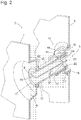
- Fig. 2 shows the pressure balance valve 5 and its surroundings partly in section, partly in perspective view.
- a piece of the metallic outer skin of the door is designated 6.
- An inner skin is formed by a deep-drawn plastic shell, which is tightly connected at their edges, not shown, with the metal sheet of the outer skin.
- a section of the inner container is designated 7.
- an opening 9 is cut, which has the shape of a circle, reduced by two segments on opposite sides.
- a first sleeve 10 has been inserted and locked before joining the inner container 7 with the outer skin 6 from the side facing away from the viewer.
- the sleeve 10 is provided at its end facing the viewer with a flange 11, which, like the opening 9, has the shape of a circle with omitted lateral segments and therefore fits through the opening 9 in an orientation rotated by 90 ° relative to the orientation shown, and in FIG Oriented orientation is locked to her.
- the inner container 7 is clamped in the configuration shown between the flange 11 and an elastically against the outer skin facing side of the inner container 7 pressing annular flange 12.
- the outer diameter of the annular flange 12 is greater than that of the opening 9, so that - in Fig. 2 not shown - insulating material that fills the gap between the outer skin 6 and inner container 7, can not get to the opening 9.
- a second annular flange 13 of smaller diameter than the first annular flange 12 is formed on the sleeve 10 adjacent to the outer skin 6 facing the end.
- This annular flange 13 is elastically on the inside of a conically widened portion 14 of a second sleeve 15 at.
- the sleeve 15 is fixed in the same manner as the sleeve 10 to the outer skin 6 by clamping it between a voltage applied to the outside of the outer skin 6 flange 16 and a voltage applied to the inner elastic annular flange 17.
- the elasticity of the annular flange 13 allows during assembly a displacement of the two sleeves 10, 15 against each other, through which a variable thickness of the door is compensated.
- the sleeve 15 is mounted on the outer skin 6 prior to assembly with the inner container 7.
- the expanded shape of the portion 14 favors the penetration of the sleeve 10 in the sleeve 15th
- the section 14 is followed by a short cylindrical section 18 of the sleeve 15, in which the sleeve 10 is held in a form-fitting manner.
- the free end of the sleeve 10 extends into a cup-like widening 19 of the sleeve 15, which adjoins the cylindrical portion 18 and which carries the flange 16 and the annular flange 17.
- the interior of the sleeve 10 is divided by a longitudinal wall 20 diametrically.
- an elastic sheet 21 made of plastic is held astride.
- the blade 21 is of substantially elliptical shape so that its edges can snugly fit snugly against the sleeve 10 along its entire length.
- the edges of the sheet 21 are pressed against the longitudinal wall 20, and air can flow from outside to inside.
- a possible overpressure in the interior 4 acts against the entire surface of the blade 21 and pushes it outward or against the sleeve 10.
- cap part 22 prevents the sheet 21 of the internal overpressure can be pushed out of the sleeve 10, on the one hand by the cap part 22 narrows the free cross section of the sleeve 10, on the other by a transverse bar 23 which extends diametrically through a central opening 24 of the cap part 22.
Landscapes
- Engineering & Computer Science (AREA)
- General Engineering & Computer Science (AREA)
- Combustion & Propulsion (AREA)
- Physics & Mathematics (AREA)
- Mechanical Engineering (AREA)
- Thermal Sciences (AREA)
- Chemical & Material Sciences (AREA)
- Refrigerator Housings (AREA)
- Safety Valves (AREA)
- Valve Housings (AREA)
- Measuring Pulse, Heart Rate, Blood Pressure Or Blood Flow (AREA)
- Packages (AREA)
- Cold Air Circulating Systems And Constructional Details In Refrigerators (AREA)
- Massaging Devices (AREA)
Priority Applications (1)
| Application Number | Priority Date | Filing Date | Title |
|---|---|---|---|
| PL07726823T PL2005085T3 (pl) | 2006-04-05 | 2007-03-13 | Obudowa urządzenia i zawór wyrównujący ciśnienie do niego |
Applications Claiming Priority (2)
| Application Number | Priority Date | Filing Date | Title |
|---|---|---|---|
| DE202006005549U DE202006005549U1 (de) | 2006-04-05 | 2006-04-05 | Gerätegehäuse und Druckausgleichsventil dafür |
| PCT/EP2007/052317 WO2007115881A2 (de) | 2006-04-05 | 2007-03-13 | Gerätegehäuse und druckausgleichsventil dafür |
Publications (2)
| Publication Number | Publication Date |
|---|---|
| EP2005085A2 EP2005085A2 (de) | 2008-12-24 |
| EP2005085B1 true EP2005085B1 (de) | 2017-05-10 |
Family
ID=36600073
Family Applications (1)
| Application Number | Title | Priority Date | Filing Date |
|---|---|---|---|
| EP07726823.3A Active EP2005085B1 (de) | 2006-04-05 | 2007-03-13 | Gerätegehäuse und druckausgleichsventil dafür |
Country Status (6)
| Country | Link |
|---|---|
| EP (1) | EP2005085B1 (pl) |
| CN (1) | CN101410680B (pl) |
| DE (1) | DE202006005549U1 (pl) |
| PL (1) | PL2005085T3 (pl) |
| RU (1) | RU2433361C2 (pl) |
| WO (1) | WO2007115881A2 (pl) |
Families Citing this family (2)
| Publication number | Priority date | Publication date | Assignee | Title |
|---|---|---|---|---|
| DE102015220351A1 (de) * | 2015-10-20 | 2017-04-20 | BSH Hausgeräte GmbH | Haushaltskältegerät mit einem Kühlraum und einem Gefrierraum und einem Druckausgleichsventil |
| DE102018219746A1 (de) * | 2018-11-19 | 2020-05-20 | BSH Hausgeräte GmbH | Kältegerät mit Leitungsdurchführung |
Family Cites Families (5)
| Publication number | Priority date | Publication date | Assignee | Title |
|---|---|---|---|---|
| GB1408006A (en) * | 1971-11-22 | 1975-10-01 | Fermod | Device for communicating with free air in particular for cold room |
| DE8601844U1 (de) * | 1986-01-25 | 1989-01-12 | Licentia Patent-Verwaltungs-Gmbh, 6000 Frankfurt | Kühl- oder Gefriergerät mit Kühlraumbelüftung |
| DE3733602A1 (de) * | 1987-10-05 | 1989-04-13 | Walther Dr Koch | Belueftungsvorrichtung fuer durch eine tuer oder klappe luftdicht verschliessbare behaelter |
| US20050081555A1 (en) * | 2003-10-20 | 2005-04-21 | Seiss Richard A. | Relief port |
| ITMI20040115A1 (it) * | 2004-01-28 | 2004-04-28 | Whirlpool Co | Valvola compensatrice per congelatori |
-
2006
- 2006-04-05 DE DE202006005549U patent/DE202006005549U1/de not_active Expired - Lifetime
-
2007
- 2007-03-13 PL PL07726823T patent/PL2005085T3/pl unknown
- 2007-03-13 WO PCT/EP2007/052317 patent/WO2007115881A2/de not_active Ceased
- 2007-03-13 EP EP07726823.3A patent/EP2005085B1/de active Active
- 2007-03-13 RU RU2008142272/13A patent/RU2433361C2/ru active
- 2007-03-13 CN CN2007800108419A patent/CN101410680B/zh not_active Expired - Fee Related
Also Published As
| Publication number | Publication date |
|---|---|
| EP2005085A2 (de) | 2008-12-24 |
| CN101410680A (zh) | 2009-04-15 |
| CN101410680B (zh) | 2010-09-22 |
| RU2008142272A (ru) | 2010-05-10 |
| RU2433361C2 (ru) | 2011-11-10 |
| PL2005085T3 (pl) | 2017-10-31 |
| WO2007115881A2 (de) | 2007-10-18 |
| WO2007115881A3 (de) | 2007-12-13 |
| DE202006005549U1 (de) | 2006-06-08 |
Similar Documents
| Publication | Publication Date | Title |
|---|---|---|
| EP1970254B1 (de) | Dübel zum Einsetzen in eine Öffnung einer Wand, insbesondere an einer Fahrzeugkarosserie | |
| EP2059738A1 (de) | Kältegerät mit druckausgleichsventil | |
| EP4045857A1 (de) | Haushaltskältegerätevorrichtung | |
| WO2008006353A1 (de) | Anbindungsvorrichtung für eine halteeinrichtung eines deckels eines öffnungsfähigen fahrzeugdaches | |
| EP2005085B1 (de) | Gerätegehäuse und druckausgleichsventil dafür | |
| EP2059746A2 (de) | Kabeldurchführung | |
| DE3723394A1 (de) | Daemmkassette und verfahren zu ihrer herstellung | |
| WO2013102471A1 (de) | Rückschlagventil | |
| DE102019104398A1 (de) | Isoliertes Befestigungssystem für Stellglieder | |
| DE102015204410B4 (de) | Wickelwelleneinheit zur Aufnahme einer Rollobahn | |
| EP3168375B1 (de) | Wandarmatur | |
| DE102007008707A1 (de) | Kühlgerät | |
| EP2156113A2 (de) | Gehäuse für ein kältegerät | |
| WO2019105918A1 (de) | Getriebe mit separatem entlüfterelement | |
| DE102011112049B4 (de) | Gurtschlossbaugruppe | |
| DE102008005784A1 (de) | Durchführungsvorrichtung | |
| DE102013220304A1 (de) | Haushaltsgerät mit einem eine Elektroniktasche und einen Deckel dazu aufweisenden Gehäuse | |
| DE102008030959A1 (de) | Montageverbindung mit Federelement für Handhabe | |
| EP1697609B1 (de) | Bodentürschliesser | |
| DE102005008730B4 (de) | Luftkanal | |
| DE102004025034B4 (de) | Scharnieranordnung | |
| DE102006053265A1 (de) | Dichtungsanordnung zur Abdichtung einer Durchgangsöffnung und Montageverfahren | |
| DE102009052636B4 (de) | Montagesockel bestehend aus einem umspritzten, eine Hülse umfassenden Formteil | |
| DE102006010029A1 (de) | Kühlgerätetür sowie Türdichtung für eine derartige Kühlgerätetür | |
| DE102012012312A1 (de) | Kühl- und/oder Gefriergerät |
Legal Events
| Date | Code | Title | Description |
|---|---|---|---|
| PUAI | Public reference made under article 153(3) epc to a published international application that has entered the european phase |
Free format text: ORIGINAL CODE: 0009012 |
|
| 17P | Request for examination filed |
Effective date: 20081105 |
|
| AK | Designated contracting states |
Kind code of ref document: A2 Designated state(s): AT BE BG CH CY CZ DE DK EE ES FI FR GB GR HU IE IS IT LI LT LU LV MC MT NL PL PT RO SE SI SK TR |
|
| DAX | Request for extension of the european patent (deleted) | ||
| RAP1 | Party data changed (applicant data changed or rights of an application transferred) |
Owner name: BSH HAUSGERAETE GMBH |
|
| 17Q | First examination report despatched |
Effective date: 20160217 |
|
| GRAP | Despatch of communication of intention to grant a patent |
Free format text: ORIGINAL CODE: EPIDOSNIGR1 |
|
| INTG | Intention to grant announced |
Effective date: 20161124 |
|
| GRAS | Grant fee paid |
Free format text: ORIGINAL CODE: EPIDOSNIGR3 |
|
| GRAA | (expected) grant |
Free format text: ORIGINAL CODE: 0009210 |
|
| AK | Designated contracting states |
Kind code of ref document: B1 Designated state(s): AT BE BG CH CY CZ DE DK EE ES FI FR GB GR HU IE IS IT LI LT LU LV MC MT NL PL PT RO SE SI SK TR |
|
| REG | Reference to a national code |
Ref country code: GB Ref legal event code: FG4D Free format text: NOT ENGLISH |
|
| REG | Reference to a national code |
Ref country code: AT Ref legal event code: REF Ref document number: 892800 Country of ref document: AT Kind code of ref document: T Effective date: 20170515 Ref country code: CH Ref legal event code: EP |
|
| REG | Reference to a national code |
Ref country code: IE Ref legal event code: FG4D Free format text: LANGUAGE OF EP DOCUMENT: GERMAN |
|
| REG | Reference to a national code |
Ref country code: DE Ref legal event code: R096 Ref document number: 502007015633 Country of ref document: DE |
|
| REG | Reference to a national code |
Ref country code: NL Ref legal event code: MP Effective date: 20170510 |
|
| REG | Reference to a national code |
Ref country code: LT Ref legal event code: MG4D |
|
| PG25 | Lapsed in a contracting state [announced via postgrant information from national office to epo] |
Ref country code: GR Free format text: LAPSE BECAUSE OF FAILURE TO SUBMIT A TRANSLATION OF THE DESCRIPTION OR TO PAY THE FEE WITHIN THE PRESCRIBED TIME-LIMIT Effective date: 20170811 Ref country code: ES Free format text: LAPSE BECAUSE OF FAILURE TO SUBMIT A TRANSLATION OF THE DESCRIPTION OR TO PAY THE FEE WITHIN THE PRESCRIBED TIME-LIMIT Effective date: 20170510 Ref country code: LT Free format text: LAPSE BECAUSE OF FAILURE TO SUBMIT A TRANSLATION OF THE DESCRIPTION OR TO PAY THE FEE WITHIN THE PRESCRIBED TIME-LIMIT Effective date: 20170510 Ref country code: FI Free format text: LAPSE BECAUSE OF FAILURE TO SUBMIT A TRANSLATION OF THE DESCRIPTION OR TO PAY THE FEE WITHIN THE PRESCRIBED TIME-LIMIT Effective date: 20170510 |
|
| PG25 | Lapsed in a contracting state [announced via postgrant information from national office to epo] |
Ref country code: IS Free format text: LAPSE BECAUSE OF FAILURE TO SUBMIT A TRANSLATION OF THE DESCRIPTION OR TO PAY THE FEE WITHIN THE PRESCRIBED TIME-LIMIT Effective date: 20170910 Ref country code: LV Free format text: LAPSE BECAUSE OF FAILURE TO SUBMIT A TRANSLATION OF THE DESCRIPTION OR TO PAY THE FEE WITHIN THE PRESCRIBED TIME-LIMIT Effective date: 20170510 Ref country code: SE Free format text: LAPSE BECAUSE OF FAILURE TO SUBMIT A TRANSLATION OF THE DESCRIPTION OR TO PAY THE FEE WITHIN THE PRESCRIBED TIME-LIMIT Effective date: 20170510 Ref country code: NL Free format text: LAPSE BECAUSE OF FAILURE TO SUBMIT A TRANSLATION OF THE DESCRIPTION OR TO PAY THE FEE WITHIN THE PRESCRIBED TIME-LIMIT Effective date: 20170510 Ref country code: BG Free format text: LAPSE BECAUSE OF FAILURE TO SUBMIT A TRANSLATION OF THE DESCRIPTION OR TO PAY THE FEE WITHIN THE PRESCRIBED TIME-LIMIT Effective date: 20170810 |
|
| PG25 | Lapsed in a contracting state [announced via postgrant information from national office to epo] |
Ref country code: CZ Free format text: LAPSE BECAUSE OF FAILURE TO SUBMIT A TRANSLATION OF THE DESCRIPTION OR TO PAY THE FEE WITHIN THE PRESCRIBED TIME-LIMIT Effective date: 20170510 Ref country code: SK Free format text: LAPSE BECAUSE OF FAILURE TO SUBMIT A TRANSLATION OF THE DESCRIPTION OR TO PAY THE FEE WITHIN THE PRESCRIBED TIME-LIMIT Effective date: 20170510 Ref country code: RO Free format text: LAPSE BECAUSE OF FAILURE TO SUBMIT A TRANSLATION OF THE DESCRIPTION OR TO PAY THE FEE WITHIN THE PRESCRIBED TIME-LIMIT Effective date: 20170510 Ref country code: EE Free format text: LAPSE BECAUSE OF FAILURE TO SUBMIT A TRANSLATION OF THE DESCRIPTION OR TO PAY THE FEE WITHIN THE PRESCRIBED TIME-LIMIT Effective date: 20170510 Ref country code: DK Free format text: LAPSE BECAUSE OF FAILURE TO SUBMIT A TRANSLATION OF THE DESCRIPTION OR TO PAY THE FEE WITHIN THE PRESCRIBED TIME-LIMIT Effective date: 20170510 |
|
| REG | Reference to a national code |
Ref country code: DE Ref legal event code: R097 Ref document number: 502007015633 Country of ref document: DE |
|
| PLBE | No opposition filed within time limit |
Free format text: ORIGINAL CODE: 0009261 |
|
| STAA | Information on the status of an ep patent application or granted ep patent |
Free format text: STATUS: NO OPPOSITION FILED WITHIN TIME LIMIT |
|
| 26N | No opposition filed |
Effective date: 20180213 |
|
| PG25 | Lapsed in a contracting state [announced via postgrant information from national office to epo] |
Ref country code: SI Free format text: LAPSE BECAUSE OF FAILURE TO SUBMIT A TRANSLATION OF THE DESCRIPTION OR TO PAY THE FEE WITHIN THE PRESCRIBED TIME-LIMIT Effective date: 20170510 |
|
| PG25 | Lapsed in a contracting state [announced via postgrant information from national office to epo] |
Ref country code: MT Free format text: LAPSE BECAUSE OF FAILURE TO SUBMIT A TRANSLATION OF THE DESCRIPTION OR TO PAY THE FEE WITHIN THE PRESCRIBED TIME-LIMIT Effective date: 20170510 |
|
| REG | Reference to a national code |
Ref country code: CH Ref legal event code: PL |
|
| GBPC | Gb: european patent ceased through non-payment of renewal fee |
Effective date: 20180313 |
|
| PG25 | Lapsed in a contracting state [announced via postgrant information from national office to epo] |
Ref country code: MC Free format text: LAPSE BECAUSE OF FAILURE TO SUBMIT A TRANSLATION OF THE DESCRIPTION OR TO PAY THE FEE WITHIN THE PRESCRIBED TIME-LIMIT Effective date: 20170510 |
|
| REG | Reference to a national code |
Ref country code: BE Ref legal event code: MM Effective date: 20180331 |
|
| REG | Reference to a national code |
Ref country code: IE Ref legal event code: MM4A |
|
| PG25 | Lapsed in a contracting state [announced via postgrant information from national office to epo] |
Ref country code: LU Free format text: LAPSE BECAUSE OF NON-PAYMENT OF DUE FEES Effective date: 20180313 |
|
| PG25 | Lapsed in a contracting state [announced via postgrant information from national office to epo] |
Ref country code: IE Free format text: LAPSE BECAUSE OF NON-PAYMENT OF DUE FEES Effective date: 20180313 |
|
| PG25 | Lapsed in a contracting state [announced via postgrant information from national office to epo] |
Ref country code: BE Free format text: LAPSE BECAUSE OF NON-PAYMENT OF DUE FEES Effective date: 20180331 Ref country code: GB Free format text: LAPSE BECAUSE OF NON-PAYMENT OF DUE FEES Effective date: 20180313 Ref country code: CH Free format text: LAPSE BECAUSE OF NON-PAYMENT OF DUE FEES Effective date: 20180331 Ref country code: LI Free format text: LAPSE BECAUSE OF NON-PAYMENT OF DUE FEES Effective date: 20180331 |
|
| PG25 | Lapsed in a contracting state [announced via postgrant information from national office to epo] |
Ref country code: FR Free format text: LAPSE BECAUSE OF NON-PAYMENT OF DUE FEES Effective date: 20180331 |
|
| REG | Reference to a national code |
Ref country code: AT Ref legal event code: MM01 Ref document number: 892800 Country of ref document: AT Kind code of ref document: T Effective date: 20180313 |
|
| PG25 | Lapsed in a contracting state [announced via postgrant information from national office to epo] |
Ref country code: AT Free format text: LAPSE BECAUSE OF NON-PAYMENT OF DUE FEES Effective date: 20180313 |
|
| PG25 | Lapsed in a contracting state [announced via postgrant information from national office to epo] |
Ref country code: HU Free format text: LAPSE BECAUSE OF FAILURE TO SUBMIT A TRANSLATION OF THE DESCRIPTION OR TO PAY THE FEE WITHIN THE PRESCRIBED TIME-LIMIT; INVALID AB INITIO Effective date: 20070313 Ref country code: PT Free format text: LAPSE BECAUSE OF FAILURE TO SUBMIT A TRANSLATION OF THE DESCRIPTION OR TO PAY THE FEE WITHIN THE PRESCRIBED TIME-LIMIT Effective date: 20170510 |
|
| PG25 | Lapsed in a contracting state [announced via postgrant information from national office to epo] |
Ref country code: CY Free format text: LAPSE BECAUSE OF FAILURE TO SUBMIT A TRANSLATION OF THE DESCRIPTION OR TO PAY THE FEE WITHIN THE PRESCRIBED TIME-LIMIT Effective date: 20170510 |
|
| PGFP | Annual fee paid to national office [announced via postgrant information from national office to epo] |
Ref country code: PL Payment date: 20220302 Year of fee payment: 16 |
|
| PGFP | Annual fee paid to national office [announced via postgrant information from national office to epo] |
Ref country code: IT Payment date: 20220331 Year of fee payment: 16 |
|
| REG | Reference to a national code |
Ref country code: DE Ref legal event code: R084 Ref document number: 502007015633 Country of ref document: DE |
|
| PG25 | Lapsed in a contracting state [announced via postgrant information from national office to epo] |
Ref country code: IT Free format text: LAPSE BECAUSE OF NON-PAYMENT OF DUE FEES Effective date: 20230313 |
|
| PG25 | Lapsed in a contracting state [announced via postgrant information from national office to epo] |
Ref country code: PL Free format text: LAPSE BECAUSE OF NON-PAYMENT OF DUE FEES Effective date: 20230313 |
|
| PG25 | Lapsed in a contracting state [announced via postgrant information from national office to epo] |
Ref country code: PL Free format text: LAPSE BECAUSE OF NON-PAYMENT OF DUE FEES Effective date: 20230313 |
|
| PGFP | Annual fee paid to national office [announced via postgrant information from national office to epo] |
Ref country code: DE Payment date: 20260331 Year of fee payment: 20 |
|
| PGFP | Annual fee paid to national office [announced via postgrant information from national office to epo] |
Ref country code: TR Payment date: 20260305 Year of fee payment: 20 |