EP2004354B1 - Schneidenträger und fräsmesserkopf - Google Patents
Schneidenträger und fräsmesserkopf Download PDFInfo
- Publication number
- EP2004354B1 EP2004354B1 EP07722190A EP07722190A EP2004354B1 EP 2004354 B1 EP2004354 B1 EP 2004354B1 EP 07722190 A EP07722190 A EP 07722190A EP 07722190 A EP07722190 A EP 07722190A EP 2004354 B1 EP2004354 B1 EP 2004354B1
- Authority
- EP
- European Patent Office
- Prior art keywords
- cutter
- support according
- bevel
- cutter support
- cutting edge
- Prior art date
- Legal status (The legal status is an assumption and is not a legal conclusion. Google has not performed a legal analysis and makes no representation as to the accuracy of the status listed.)
- Not-in-force
Links
Images

Classifications
-
- B—PERFORMING OPERATIONS; TRANSPORTING
- B23—MACHINE TOOLS; METAL-WORKING NOT OTHERWISE PROVIDED FOR
- B23C—MILLING
- B23C5/00—Milling-cutters
- B23C5/16—Milling-cutters characterised by physical features other than shape
- B23C5/20—Milling-cutters characterised by physical features other than shape with removable cutter bits or teeth or cutting inserts
- B23C5/22—Securing arrangements for bits or teeth or cutting inserts
- B23C5/24—Securing arrangements for bits or teeth or cutting inserts adjustable
- B23C5/2462—Securing arrangements for bits or teeth or cutting inserts adjustable the adjusting means being oblique surfaces
-
- B—PERFORMING OPERATIONS; TRANSPORTING
- B23—MACHINE TOOLS; METAL-WORKING NOT OTHERWISE PROVIDED FOR
- B23C—MILLING
- B23C5/00—Milling-cutters
- B23C5/02—Milling-cutters characterised by the shape of the cutter
- B23C5/10—Shank-type cutters, i.e. with an integral shaft
- B23C5/1081—Shank-type cutters, i.e. with an integral shaft with permanently fixed cutting inserts
-
- B—PERFORMING OPERATIONS; TRANSPORTING
- B23—MACHINE TOOLS; METAL-WORKING NOT OTHERWISE PROVIDED FOR
- B23C—MILLING
- B23C5/00—Milling-cutters
- B23C5/16—Milling-cutters characterised by physical features other than shape
- B23C5/18—Milling-cutters characterised by physical features other than shape with permanently-fixed cutter-bits or teeth
-
- B—PERFORMING OPERATIONS; TRANSPORTING
- B23—MACHINE TOOLS; METAL-WORKING NOT OTHERWISE PROVIDED FOR
- B23C—MILLING
- B23C5/00—Milling-cutters
- B23C5/16—Milling-cutters characterised by physical features other than shape
- B23C5/20—Milling-cutters characterised by physical features other than shape with removable cutter bits or teeth or cutting inserts
- B23C5/22—Securing arrangements for bits or teeth or cutting inserts
- B23C5/2265—Securing arrangements for bits or teeth or cutting inserts by means of a wedge
- B23C5/2278—Securing arrangements for bits or teeth or cutting inserts by means of a wedge for plate-like cutting inserts fitted on an intermediate carrier, e.g. shank fixed in the cutter body
-
- B—PERFORMING OPERATIONS; TRANSPORTING
- B23—MACHINE TOOLS; METAL-WORKING NOT OTHERWISE PROVIDED FOR
- B23C—MILLING
- B23C5/00—Milling-cutters
- B23C5/16—Milling-cutters characterised by physical features other than shape
- B23C5/20—Milling-cutters characterised by physical features other than shape with removable cutter bits or teeth or cutting inserts
- B23C5/22—Securing arrangements for bits or teeth or cutting inserts
- B23C5/24—Securing arrangements for bits or teeth or cutting inserts adjustable
- B23C5/2472—Securing arrangements for bits or teeth or cutting inserts adjustable the adjusting means being screws
-
- B—PERFORMING OPERATIONS; TRANSPORTING
- B23—MACHINE TOOLS; METAL-WORKING NOT OTHERWISE PROVIDED FOR
- B23C—MILLING
- B23C2215/00—Details of workpieces
- B23C2215/20—Crankshafts
-
- B—PERFORMING OPERATIONS; TRANSPORTING
- B23—MACHINE TOOLS; METAL-WORKING NOT OTHERWISE PROVIDED FOR
- B23C—MILLING
- B23C2226/00—Materials of tools or workpieces not comprising a metal
- B23C2226/12—Boron nitride
- B23C2226/125—Boron nitride cubic [CBN]
-
- B—PERFORMING OPERATIONS; TRANSPORTING
- B23—MACHINE TOOLS; METAL-WORKING NOT OTHERWISE PROVIDED FOR
- B23C—MILLING
- B23C2226/00—Materials of tools or workpieces not comprising a metal
- B23C2226/31—Diamond
- B23C2226/315—Diamond polycrystalline [PCD]
-
- B—PERFORMING OPERATIONS; TRANSPORTING
- B23—MACHINE TOOLS; METAL-WORKING NOT OTHERWISE PROVIDED FOR
- B23C—MILLING
- B23C2240/00—Details of connections of tools or workpieces
- B23C2240/08—Brazed connections
-
- B—PERFORMING OPERATIONS; TRANSPORTING
- B23—MACHINE TOOLS; METAL-WORKING NOT OTHERWISE PROVIDED FOR
- B23C—MILLING
- B23C2240/00—Details of connections of tools or workpieces
- B23C2240/16—Welded connections
-
- Y—GENERAL TAGGING OF NEW TECHNOLOGICAL DEVELOPMENTS; GENERAL TAGGING OF CROSS-SECTIONAL TECHNOLOGIES SPANNING OVER SEVERAL SECTIONS OF THE IPC; TECHNICAL SUBJECTS COVERED BY FORMER USPC CROSS-REFERENCE ART COLLECTIONS [XRACs] AND DIGESTS
- Y10—TECHNICAL SUBJECTS COVERED BY FORMER USPC
- Y10T—TECHNICAL SUBJECTS COVERED BY FORMER US CLASSIFICATION
- Y10T407/00—Cutters, for shaping
- Y10T407/19—Rotary cutting tool
- Y10T407/1906—Rotary cutting tool including holder [i.e., head] having seat for inserted tool
- Y10T407/1932—Rotary cutting tool including holder [i.e., head] having seat for inserted tool with means to fasten tool seat to holder
-
- Y—GENERAL TAGGING OF NEW TECHNOLOGICAL DEVELOPMENTS; GENERAL TAGGING OF CROSS-SECTIONAL TECHNOLOGIES SPANNING OVER SEVERAL SECTIONS OF THE IPC; TECHNICAL SUBJECTS COVERED BY FORMER USPC CROSS-REFERENCE ART COLLECTIONS [XRACs] AND DIGESTS
- Y10—TECHNICAL SUBJECTS COVERED BY FORMER USPC
- Y10T—TECHNICAL SUBJECTS COVERED BY FORMER US CLASSIFICATION
- Y10T407/00—Cutters, for shaping
- Y10T407/22—Cutters, for shaping including holder having seat for inserted tool
- Y10T407/2272—Cutters, for shaping including holder having seat for inserted tool with separate means to fasten tool to holder
- Y10T407/2282—Cutters, for shaping including holder having seat for inserted tool with separate means to fasten tool to holder including tool holding clamp and clamp actuator
- Y10T407/2284—Wedge clamp element
-
- Y—GENERAL TAGGING OF NEW TECHNOLOGICAL DEVELOPMENTS; GENERAL TAGGING OF CROSS-SECTIONAL TECHNOLOGIES SPANNING OVER SEVERAL SECTIONS OF THE IPC; TECHNICAL SUBJECTS COVERED BY FORMER USPC CROSS-REFERENCE ART COLLECTIONS [XRACs] AND DIGESTS
- Y10—TECHNICAL SUBJECTS COVERED BY FORMER USPC
- Y10T—TECHNICAL SUBJECTS COVERED BY FORMER US CLASSIFICATION
- Y10T409/00—Gear cutting, milling, or planing
- Y10T409/30—Milling
- Y10T409/30952—Milling with cutter holder
Definitions
- the invention relates to a blade carrier for attachment in a Fräsmesserkopf, consisting of a shaft-shaped pin and a head with soldered cutting edges with a side edge formed by a rake surface and an open space.
- the invention further relates to a Fräsmesserkopf with a plurality of cutting carriers used in recesses of a base body, are soldered to the respective cutting, the blade carriers are each axially adjustable via a wedge body and means-clamping elements in the Fräsmesserkopf fixable.
- the above-described Fräsmesserkopf is in principle from the DE 40 03 862 known.
- the recesses for the blade carrier extend in the blade head described there from the one end face of its base parallel to the axis of rotation and at a distance from the circumference, the cutting edges of the inserts used projecting only slightly beyond the end face of the base body.
- the axis of the serving for bracing round wedges each skewed to the axes of the cutting plates supporting cutting plate carrier.
- another round wedge with differential screw for axial adjustment of each cutting plate is provided and arranged in a recess which extends radially inwardly from the circumference of the base body. For axial adjustment and radially outward bracing geometrically equal round wedges are used.
- this cutter head As an advantage of this cutter head is highlighted that due to the position of the cutting plate carrier receiving recesses parallel to the axis of rotation of the body only radially directed centrifugal forces occur without axial components. These forces can be well intercepted, because the recesses are not located directly on the circumference of the body, but radially inwardly at a distance from the circumference.
- the knife head is therefore also suitable for extremely high speeds and the centrifugal forces occurring then.
- a fine adjustment of the cutting elements in the axial direction without interference with radial components is possible.
- crankshafts for cars have been subjected to finish machining by grinding or belt grinding, wherein the grinding has been carried out by the use of cooling lubricants, with the development of suitable milling tools, the grinding of the crankshafts could be replaced by milling processes.
- an orthogonal rotary milling with eccentric tool adjustment without axial feed is used.
- the tool executes a lowering movement, due to which the shape design of the bearing seats is generated exclusively by the tool cutting edge.
- the tool must be adjusted to the workpiece so that it is ensured that during the engagement of the minor cutting the entire apex line of the bearing seat is covered.
- the bearing seat diameter to be manufactured is generated via this vertex line. Due to the process, middle regions of the secondary cutting edge are engaged longer than other regions. This causes the cutting edge in the middle area to show a higher level of wear than in the outer areas.
- orthogonal rotary milling with eccentric tool adjustment without axial feed has a decisive disadvantage. Due to the fact that the tool cutting edge carries out a lowering operation in this method, the smallest cutting errors or the tool wear immediately have a negative effect on the shape and surface quality to be achieved. In particular, the different forms of tool wear leads to an earlier form deviation.
- the former object is achieved by a blade carrier according to claim 1.
- the blade carrier has a chamfer adjacent to the secondary cutting edge and arranged on the free surface, with a chamfer width decreasing outwards to 0 in each case. Further embodiments of the blade carrier are described in the subclaims.
- a Fräsmesserkopf according to claim 10 which is characterized by three blade carrier, which are arranged in equidistant angular distance from each other.
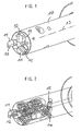
- the in Fig. 1 to 3 Milling cutter head shown essentially consists of a base body 10, in which three blade carrier 11 are soldered with each soldered cutting 12.
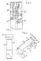
- the blade carriers 11 are each arranged in parallel to the longitudinal axis 13 holes 22 (see Fig. 3 ) used.
- Further bores in the main body 10 are provided substantially in the radial direction or slightly inclined thereto, in which wedge bodies 14 are arranged, which are displaceable in the radial direction via an adjusting screw 15, preferably a double-threaded screw.
- the wedge body 14 have wedge surfaces 16 which extend obliquely to the radial plane of the base body, so that during a radial movement of the wedge body 14 of the blade carrier 11 along its longitudinal axis, ie in the axial direction, is displaceable.
- the clamping piece 18 which is centrally located and has three clamping surfaces 19, which bear against corresponding clamping surfaces of the blade carrier 11.
- the clamping piece 18 can be fixed by means of a screw 21, which is preferably designed as a double-threaded screw.
- the clamping piece 18 is used in the illustrated case for the fixation of three blade carriers 11, each having a flat surface 20.
- each blade carrier 11 can be adjusted axially via a circular wedge and the associated screw 15. For the axis-parallel alignment of the blade carrier and thus the cutting serve the holes 22.
- the surface 23 serves to ensure that there is no line contact between the blade carrier 11 and bore 22.
- the cutter support 11 also has an inclined surface 24, the inclination of which corresponds to the inclination of a surface 19 of the clamping piece.
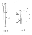
- Fig. 7 . 9 and 10 show enlarged views of the cutting edges;
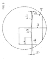
- Fig. 8 shows an optional embodiment in which the inner and the outer cutting area are angled relative to the central cutting area.
- the chamfer 29 serving as Vorverschl fashionfase has the task to emulate the characteristic of the process wear pattern, taking into account the required concave inwardly extending cutting fall.
- the degressive wear process is shortened.
- the free surface of the cutting edge 25 while maintaining the clearance angle is ground either roof-shaped (for large radii and short cutting lengths) or as in Fig. 9 shown convexly ground under a radius R, which is preferably about 900 mm.
- Fig. 9 By training after Fig. 9 results in a distance of the highest point 27 of the cutting edge from the lowest point of 4 microns. If a bevel 29 is ground on the free surface 28 in a second operation, wherein the camber angle of the cutting edge is maintained, resulting in Fig. 10 illustrated embodiment of the bevel, which has approximately the middle of the cutting edge 25, the largest width of 4 microns.
- the chamfer extends to the ends of the cutting edge 25 and to a short-term location, wherein the chamfer 29 runs continuously narrower to a width of 0 mm on both sides. The chamfer thus results from a tendon-like section of a roof-shaped or convex free surface, which is arranged at a clearance angle of 10 °.
- the rake angle is uniformly 0 °.
- the cutting edges 12 are ground concave at a camber angle of 90 ° or a slightly smaller angle to the axis of rotation of the tool, resulting in the 4 ⁇ m increase in the point 27.
- a 5 ° angled secondary cutting part which is followed by a secondary cutting part 25b, which is perpendicular to the longitudinal axis 26 which is parallel to the axis of rotation 13, is arranged.
- a secondary cutting part 25c which is also inclined by 5 °.
Landscapes
- Engineering & Computer Science (AREA)
- Mechanical Engineering (AREA)
- Milling Processes (AREA)
- Shearing Machines (AREA)
- Knives (AREA)
Description
- Die Erfindung betrifft einen Schneidenträger zur Befestigung in einem Fräsmesserkopf, bestehend aus einem schaftförmigen Stift und einem Kopf mit eingelöteten Schneiden mit einer von einer Spanfläche und einer Freifläche gebildeten Nebenschneidkante.
- Die Erfindung betrifft ferner einen Fräsmesserkopf mit mehreren, in Ausnehmungen eines Grundkörpers eingesetzten Schneidenträgern, auf die jeweils Schneiden aufgelötet sind, wobei die Schneidenträger jeweils über einen Keilkörper axial verstellbar und mittels-Klemmelementen im Fräsmesserkopf fixierbar sind.
- Der vorbeschriebene Fräsmesserkopf ist prinzipiell aus der
DE 40 03 862 bekannt. Die Ausnehmungen für die Schneidenträger erstrecken sich bei dem dort beschriebenen Messerkopf von der einen Stirnfläche seines Grundkörpers parallel zu dessen Drehachse sowie im Abstand vom Umfang, wobei die Schneiden der verwendeten Schneidplatten nur wenig über die Stirnfläche des Grundkörpers vorstehen. Ferner stehen die Achse der zum Verspannen dienenden Rundkeile jeweils windschief zu den Achsen der die Schneidplatten tragenden Schneidplattenträger. Schließlich ist auch noch jeweils ein weiterer Rundkeil mit Differentialschraube zur axialen Einstellung einer jeden Schneidplatte vorgesehen und in einer Ausnehmung angeordnet, die sich vom Umfang des Grundkörpers radial einwärts erstreckt. Zur axialen Einstellung und zum radial auswärts gerichteten Verspannen werden geometrisch gleiche Rundkeile verwendet. Als Vorteil dieses Messerkopfes wird hervorgehoben, dass aufgrund der Lage der die Schneidplattenträger aufnehmenden Ausnehmungen parallel zur Drehachse des Grundkörpers nur radial gerichtete Fliehkräfte ohne Axialkomponenten auftreten. Diese Kräfte lassen sich gut abfangen, weil sich die Ausnehmungen nicht unmittelbar am Umfang des Grundkörpers, sondern radial einwärts im Abstand vom Umfang befinden. Der Messerkopf ist daher auch für extrem hohe Drehzahlen und die dann auftretenden Fliehkräfte geeignet. Vorteilhafter Weise ist eine Feineinstellung der Schneidelemente in axialer Richtung ohne Überlagerung mit radialen Komponenten möglich. - Während nach dem Stand der Technik Kurbelwellen für Pkw durch Schleifen bzw. Bandschleifen einer Finish-Bearbeitung zugeführt worden sind, wobei das Schleifen verfahrensbedingt unter Einsatz von Kühlschmierstoffen durchgeführt wurde, konnte mit der Entwicklung geeigneter Fräserwerkzeuge das Schleifen der Kurbelwellen durch Fräsverfahren abgelöst werden. Aufgrund der Bauform der Kurbelwelle wird ein orthogonales Drehfräsen mit exzentrischer Werkzeuganstellung ohne Axialvorschub angewendet. Hierbei führt das Werkzeug eine Senkbewegung aus, aufgrund der die Formgestaltung der Lagersitze ausschließlich durch die Werkzeugnebenschneide erzeugt wird. Hierbei muss das Werkzeug so zum Werkstück angestellt werden, dass sichergestellt ist, dass während des Eingriffes der Nebenschneide die gesamte Scheitellinie des Lagersitzes überdeckt wird. Der zu fertigende Lagersitzdurchmesser wird über diese Scheitellinie erzeugt. Verfahrensbedingt sind mittlere Bereiche der Nebenschneide länger im Eingriff als andere Bereiche. Dies führt dazu, dass die Schneide im mittleren Bereich einen höheren Verschleiß als in den äußeren Bereichen zeigt.
- Weitere Details über das orthogonale Drehfräsen sind beispielsweise in der
DE 10 2004 022 360 A1 beschrieben. Das orthogonale Drehfräsen mit exzentrischer Werkzeuganstellung ohne Axialvorschub hat jedoch einen entscheidenden Nachteil. Aufgrund der Tatsache, dass bei diesem Verfahren die Werkzeugnebenschneide eine Senkoperation ausführt, wirken sich kleinste Schneidenfehler bzw. der Werkzeugverschleiß sofort negativ auf die zu erreichende Form und Oberflächengüte aus. Vor allem der sich unterschiedlich ausbildende Werkzeugverschleiß führt zu einer früheren Formabweichung. - Es ist Aufgabe der vorliegenden Erfindung, die vorgenannten Nachteile zu beseitigen, insbesondere soll eine Schneidenform gefunden werden, die gleichzeitig eine formgenaue Werkstückbearbeitung als auch eine möglichst lange Standzeit gewährleistet.
- Ferner ist es Aufgabe der vorliegenden Erfindung, hierzu einen geeigneten Fräsmesserkopf anzugeben.
- Die erstgenannte Aufgabe wird durch einen Schneidenträger nach Anspruch 1 gelöst. Der Schneidenträger besitzt erfindungsgemäß eine an die Nebenschneidkante angrenzende und auf der Freifläche angeordnete Fase mit einer nach außen jeweils zu 0 abnehmenden Fasenbreite. Weitere Ausführungsformen des Schneidenträgers sind in den Unteransprüchen beschrieben.
- Die Aufgabe wird ferner durch einen Fräsmesserkopf nach Anspruch 10 gelöst, der durch drei Schneidenträger gekennzeichnet ist, die in äquidistantem Winkelmaß zueinander angeordnet sind.
- Bei den nach dem Stand der Technik bekannten Schneidenträgern ohne die erfindungsgemäße Fase ergab sich ein hoher Anfangsverschleiß in der Schneidenmitte, nämlich dem Ort, an dem die Schneide die längste Kontaktzeit mit dem Werkstück hat. Randseitig liegende Bereiche mit wesentlich kürzerem Schneideingriff zeigten hingegen einen geringeren Freiflächenverschleiß. Bei Verwendung der erfindungsgemäßen Schneidenträger konnte hingegen der degressive Verschleißbereich mit einem hohen anfänglichen Freiflächenverschleiß deutlich verkürzt werden, so dass der Bereich, in dem der Freiflächenverschleiß linear stattfindet, entsprechend verlängert wurde.
- Weitere Details der Erfindung werden anhand der Figuren erläutert. Es zeigen:
- Fig. 1
- eine perspektivische Ansicht eines Fräsmesserkopfes mit 3 Schneidenträgern,
- Fig. 2
- eine drahtmodellartige Darstellung des Fräsmesserkopfes nach
Fig. 1 , - Fig. 3
- einen Längsquerschnitt durch einen Fräsmesserkopf ohne Schneidenträger,
- Fig. 4
- eine Seitenansicht eines Schneidenträgers,
- Fig. 5
- eine Prinzipsskizze der relativen Lage eines Schneidenträgers zu einem Klemmstück und einem Keilkörper zur axialen Einstellung,
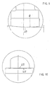
- Fig. 6
- eine weitere Seitenansicht des Schneidenträgers,
- Fig. 7
- eine Ausschnittsvergrößerung des Bereiches "A",
- Fig. 8+9
- jeweilige vergrößerte Ansichten der Schneiden gemäß
Fig. 4 in unterschiedlichen Ausführungsformen, - Fig. 10
- eine Draufsicht auf die Freifläche der Schneide und
- Fig. 11
- eine schematische Verschleißkurve.
- Der in
Fig. 1 bis 3 dargestellte Fräsmesserkopf besteht im Wesentlichen aus einem Grundkörper 10, in dem drei Schneidenträger 11 mit jeweils aufgelöteten Schneiden 12 aufgelötet sind. Die Schneidenträger 11 sind jeweils in parallel zur Längsachse 13 angeordneten Bohrungen 22 (sieheFig. 3 ) eingesetzt. Im Wesentlichen in radialer Richtung bzw. leicht hierzu geneigt sind weitere Bohrungen im Grundkörper 10 vorgesehen, in denen Keilkörper 14 angeordnet sind, die über eine Justierschraube 15, vorzugsweise eine Doppelgewindeschraube, in radialer Richtung verschiebbar sind. - Wie aus
Fig. 5 ersichtlich, besitzen die Keilkörper 14 Keilflächen 16, die schräg zur Radialebene des Grundkörpers verlaufen, so dass bei einer Radialbewegung des Keilkörpers 14 der Schneidenträger 11 entlang seiner Längsachse, d. h. in axialer Richtung, verschiebbar ist. Zur Klemmung der Schneidenträger dient das Klemmstück 18, das mittig angeordnet ist und drei Klemmflächen 19 aufweist, die an entsprechenden Klemmflächen der Schneidenträger 11 anliegen. Das Klemmstück 18 kann mittels einer Schraube 21, die vorzugsweise als Doppelgewindeschraube ausgebildet ist, fixiert werden. Das Klemmstück 18 dient im dargestellten Fall zur Fixierung von drei Schneidenträgern 11, die jeweils eine ebene Fläche 20 aufweisen. Durch die Ausbildung des Klemmstückes 18 und die Anordnung der Klemmflächen 19 in einer Triangelform wird ein exaktes Ausrichten der Schneiden 12 und der Schneidenträger 11 unter einem Winkel von 120° zueinander (sieheFig. 1 ) erreicht. Jeder Schneidenträger 11 kann über einen Rundkeil und die dazugehörige Schraube 15 axial verstellt werden. Zur achsparallelen Ausrichtung der Schneidenträger und damit der Schneiden dienen die Bohrungen 22. Die Fläche 23 dient dazu, dass sichergestellt wird, dass es zu keiner Linienberührung zwischen Schneidenträger 11 und Bohrung 22 kommt. Wie inFig. 4 dargestellt, besitzt der Schneidenträger 11 auch eine geneigte Fläche 24, deren Neigung der Neigung einer Fläche 19 des Klemmstückes entspricht. - Alternativ ist es möglich, anstelle der passgenauen Bohrungen einen außen liegenden Spannring in Verbindung mit einem axial mittig angeordneten Klemmstück zu verwenden, zwischen denen die Schneidenträger 11 fixierbar sind. Der Spannring wird dann auf den Grundkörper 10 aufgeschraubt oder aufgeschrumpft.
- Details der vorliegenden Erfindung zeigen insbesondere die
Fig. 7 ,9 und 10 , die vergrößerte Ansichten der Schneiden bzw. der Schneidenherstellung zeigen;Fig. 8 zeigt eine optionale Ausführungsform, bei der der innere und der äußere Schneidenbereich gegenüber dem mittleren Schneidenbereich abgewinkelt sind. - Die als Vorverschleißfase dienende Fase 29 hat die Aufgabe, das für das Verfahren charakteristische Verschleißbild unter Berücksichtigung des erforderlichen konkav nach innen verlaufenden Schneidensturzes nachzubilden. Somit wird der degressive Verschleißverlauf verkürzt. Man setzt sozusagen gleich im linearen Verschleißbereich ein. Würde man keine Vorverschleißfase unter Berücksichtigung des erforderlichen konkav nach innen verlaufenden Schneidensturzes auf die Schneide schleifen, käme es zu einer Formabweichung bereits im degressiven Verschleißbereich und somit zum Standzeitende durch Formabweichung.
- Um zu der erfindungsgemäßen Schneidenform zu gelangen, wird die Freifläche der Schneide 25 unter Beibehaltung des Freiwinkels entweder (bei großen Radien und kurzen Schneidenlängen) dachförmig angeschliffen oder wie in
Fig. 9 dargestellt, konvex unter einem Radius R geschliffen, der vorzugsweise etwa 900 mm beträgt. - Durch die Ausbildung nach
Fig. 9 ergibt sich ein Abstand des höchsten Punktes 27 der Schneide gegenüber dem niedrigsten Punkt von 4 µm. Wird in einem zweiten Arbeitsgang eine Fase 29 auf die Freifläche 28 geschliffen, wobei der Sturzwinkel der Schneide beibehalten wird, ergibt sich die inFig. 10 dargestellte Ausführungsform der Fase, die etwa mittig der Schneide 25 die größte Breite von 4 µm aufweist. Die Fase erstreckt sich bis zu den Enden der Schneidkante 25 bzw. zu einem kurz davor endenden Ort, wobei die Fase 29 kontinuierlich schmaler bis zu einer Breite von 0 mm an beiden Seiten ausläuft. Die Fase ergibt sich somit aus einem sehnenartigen Schnitt einer dachförmigen oder konvex ausgebildeten Freifläche, die unter einem Freiwinkel von 10° angeordnet ist. Der Spanwinkel beträgt einheitlich 0°. Die Schneiden 12 sind unter einem Sturzwinkel von 90° bzw. einem geringfügig kleineren Winkel zur Rotationsachse des Werkzeugs konkav geschliffen, wodurch sich die 4 µm große Erhöhung des Punktes 27 ergibt. Durch diese Maßnahme wird erreicht, dass anstelle des Verschleißverlaufes gemäß Kurve 30 inFig. 11 , der sich bei nach dem Stand der Technik bekannten Schneidenträgern ergibt, ein Verschleißverlauf 31 erreicht wird, bei dem der lineare Verschleißbereich erheblich verlängert worden ist, indem der degressive Anfangsverschleißbereich um eine entsprechende Zeit verkürzt wird. - In der in
Fig. 8 dargestellten Ausführungsvariante erstreckt sich über eine Breite a von 2 mm ein um 5° abgewinkelter Nebenschneidenteil, dem ein Nebenschneidenteil 25b folgt, der senkrecht zur Längsachse 26, die parallel zu der Drehachse 13 liegt, angeordnet ist. Auf der innen liegenden Seite folgt ein Nebenschneidenteil 25c, das ebenfalls um 5° geneigt ist. - Durch die gemäß
Fig. 8 ggf. zusätzlich gewählte Ausbildung abgewinkelter Außenbereiche (Twinkappung) von einer mit Vorverschleißfase präparierten Schneide werden bewusst der innere und der äußere Schneidenbereich aus dem Schneidenkontaktbereich herausgenommen. Bei den beiden nicht mit "Twinkappung" versehenen Schneiden kommt es in diesen Bereichen zu seinem höheren Freiflächenverschleiß. Im mittleren Schneidenbereich, wo verfahrensbedingt der höchste Freiflächenbereich auftritt, schneiden alle drei Schneiden zusammen. Man nutzt das Verschleißverhalten sozusagen zugunsten der geforderten konvexen Kurbelwellenlagerform aus.
Claims (10)
- Schneidenträger zur Befestigung in einem Fräsmesserkopf, bestehend aus einem schaftförmigen Stift und einem Kopf mit eingelöteten Schneiden mit einer von einer Spanfläche und einer Freifläche gebildeten Nebenschneidkante (25),
gekennzeichnet durch
eine an die Nebenschneidkante (25) angrenzende und auf der Freifläche angeordnete Fase (29) mit einer nach außen jeweils zu 0 abnehmenden Fasenbreite. - Schneidenträger nach Anspruch 1, dadurch gekennzeichnet, dass die Fase (29) etwa mittig zur Nebenschneidkante (25) angeordnet ist.
- Schneidenträger nach Anspruch 1 oder 2, dadurch gekennzeichnet, dass die maximale Fasenbreite ≤10 µm, vorzugsweise ≤4 µm beträgt.
- Schneidenträger nach einem der Ansprüche 1 bis 3, dadurch gekennzeichnet, dass die Fasenbreite zu beiden Seiten kontinuierlich zu 0 µm abnimmt und/oder sich die Fase (29) über die gesamte Nebenschneidenbreite erstreckt.
- Schneidenträger nach einem der Ansprüche 1 bis 4, dadurch gekennzeichnet, dass die Fase (29) durch zwei aufeinander folgende Schleifoperationen hergestellt wird, nämlich einem ersten Schleifen des an die Schneidkante angrenzenden Freiflächenbereiches (28) zu einer konvexen oder dachartigen Form und einem anschließenden teilweisen Planschliff dieses Freiflächenbereiches.
- Schneidenträger nach Anspruch 5, dadurch gekennzeichnet, dass der Radius des konvex geschliffenen Freiflächenbereiches R = 900 mm ± 100 mm beträgt.
- Schneidenträger nach einem der Ansprüche 1 bis 6, dadurch gekennzeichnet, dass der Freiwinkel 10° ± 2° beträgt.
- Schneidenträger nach Anspruch 5 gekennzeichnet durch eine abgewinkelte Schneide, wobei ein mittlerer Schneidenteil (25b) senkrecht zur Stiftlängsachse und die sich seitlich hieran anschließenden Schneidenteilbereiche (25a, 25c) hierzu unter einem Winkel ≤10°, vorzugsweise ≤5° geneigt sind.
- Schneidenträger nach Anspruch 8, dadurch gekennzeichnet, dass das Verhältnis der Länge des radial außen liegenden abgewinkelten Schneidenteilbereiches (25a) zum mittleren Schneidenteilbereich (25b) 2:3 und/oder das Verhältnis der Länge des radial innen liegenden abgewinkelten Schneidenteilbereiches (25c) zum radial außen liegenden Nebenschneidenteilbereich (25a) 2:1 beträgt.
- Fräsmesserkopf mit mehreren in Ausnehmungen eines Grundkörpers eingesetzten Schneidenträgern, auf die jeweils Schneiden aufgelötet sind, wobei die Schneidenträger jeweils über einen Keilkörper axial verstellbar und mittels Klemmelementen im Fräsmesserkopf fixierbar sind,
gekennzeichnet durch
zwei Schneidenträger nach einem der Ansprüche 1 bis 9, die in äquidistantem Winkelmaß zueinander angeordnet sind.
Priority Applications (1)
| Application Number | Priority Date | Filing Date | Title |
|---|---|---|---|
| PL07722190T PL2004354T3 (pl) | 2006-04-12 | 2007-04-11 | Oprawka noża składanego i głowica frezowa |
Applications Claiming Priority (2)
| Application Number | Priority Date | Filing Date | Title |
|---|---|---|---|
| DE202006006081U DE202006006081U1 (de) | 2006-04-12 | 2006-04-12 | Schneidenträger und Fräsmesserkopf |
| PCT/DE2007/000632 WO2007115561A1 (de) | 2006-04-12 | 2007-04-11 | Schneidenträger und fräsmesserkopf |
Publications (2)
| Publication Number | Publication Date |
|---|---|
| EP2004354A1 EP2004354A1 (de) | 2008-12-24 |
| EP2004354B1 true EP2004354B1 (de) | 2009-06-03 |
Family
ID=38370399
Family Applications (1)
| Application Number | Title | Priority Date | Filing Date |
|---|---|---|---|
| EP07722190A Not-in-force EP2004354B1 (de) | 2006-04-12 | 2007-04-11 | Schneidenträger und fräsmesserkopf |
Country Status (13)
| Country | Link |
|---|---|
| US (1) | US7832963B2 (de) |
| EP (1) | EP2004354B1 (de) |
| JP (1) | JP2009533232A (de) |
| KR (1) | KR20090004948A (de) |
| CN (1) | CN101389433B (de) |
| AT (1) | ATE432786T1 (de) |
| BR (1) | BRPI0710188A2 (de) |
| CA (1) | CA2648102A1 (de) |
| DE (2) | DE202006006081U1 (de) |
| MX (1) | MX2008013021A (de) |
| PL (1) | PL2004354T3 (de) |
| RU (1) | RU2424878C2 (de) |
| WO (1) | WO2007115561A1 (de) |
Families Citing this family (1)
| Publication number | Priority date | Publication date | Assignee | Title |
|---|---|---|---|---|
| RU2714757C1 (ru) * | 2019-09-23 | 2020-02-19 | Акционерное общество "Научно-исследовательский инженерный институт" (АО "НИИИ") | Резьбофреза |
Family Cites Families (26)
| Publication number | Priority date | Publication date | Assignee | Title |
|---|---|---|---|---|
| US2780858A (en) * | 1952-09-27 | 1957-02-12 | Lawrence R Robinson | Reinforced cutting tool |
| LU35523A1 (de) * | 1956-10-27 | 1957-12-21 | ||
| US3673657A (en) * | 1968-11-22 | 1972-07-04 | Fagersta Bruks Ab | Device for clamping a cutting insert to a seat of a toolholder body |
| US3667099A (en) * | 1970-07-31 | 1972-06-06 | Du Pont | Method of securing dense, metal-bonded refractory nitride bodies to steel and product |
| JPS541099Y2 (de) * | 1975-08-09 | 1979-01-19 | ||
| US4201501A (en) * | 1977-06-27 | 1980-05-06 | Day Flory M | Cutting tool |
| US4181456A (en) * | 1978-01-06 | 1980-01-01 | Niagara Cutter Inc. | Cutting tool |
| US4264245A (en) * | 1979-08-20 | 1981-04-28 | Lindsay Harold W | Keyless holder for pin-type replaceable cutting inserts |
| CN85204586U (zh) * | 1985-10-24 | 1987-06-24 | 航天部国营风华机器厂 | 挤压式机夹可转位面铣刀 |
| JPH0137858Y2 (de) * | 1985-11-14 | 1989-11-14 | ||
| SU1511013A1 (ru) * | 1987-04-24 | 1989-09-30 | Предприятие П/Я Р-6758 | Способ фрезеровани цилиндрической поверхности |
| DE4003862A1 (de) * | 1989-08-05 | 1991-02-07 | Widia Heinlein Gmbh | Messerkopf |
| SU1756036A1 (ru) * | 1990-03-19 | 1992-08-23 | Завод Транспортного Машиностроения Им.Я.М.Свердлова | Торцова фреза |
| SE502196C2 (sv) * | 1990-12-03 | 1995-09-11 | Sandvik Ab | Vändskär med positiv spånvinkel, samt fräsverktyg, företrädesvis för hörnfräsning |
| JP2522862Y2 (ja) * | 1991-03-28 | 1997-01-16 | 三菱マテリアル株式会社 | 転削工具 |
| CN2221459Y (zh) * | 1994-07-20 | 1996-03-06 | 桂育鹏 | 错齿通用式可转位面铣刀 |
| DE19516893A1 (de) * | 1995-05-09 | 1996-11-14 | Widia Gmbh | Schneideinsatz und Fräswerkzeug |
| US5876160A (en) * | 1996-08-21 | 1999-03-02 | Ingersoll Cutting Tool Company | Milling with insert having cutting-edge land of width increasing with depth of cut |
| DE10006431C1 (de) * | 2000-02-14 | 2001-09-27 | Felix Leeb | Fräs- u. Drehwerkzeug |
| JP2002059308A (ja) * | 2000-08-21 | 2002-02-26 | Tadashi Sugiyama | フライスカッター |
| JP4228557B2 (ja) | 2001-02-05 | 2009-02-25 | 三菱マテリアル株式会社 | スローアウェイチップ |
| CA2531425C (en) * | 2003-07-09 | 2011-09-06 | Kennametal Widia Produktions Gmbh & Co. Kg | Cutting insert |
| JP2005111651A (ja) * | 2003-09-19 | 2005-04-28 | Tungaloy Corp | チップおよびフライスカッタおよびそれらを用いた加工方法 |
| JP4706284B2 (ja) * | 2004-04-06 | 2011-06-22 | 三菱マテリアル株式会社 | インサート着脱式転削工具 |
| DE102004022360B4 (de) | 2004-04-30 | 2018-05-09 | Gebr. Heller Maschinenfabrik Gmbh | Verfahren zur Feinbearbeitung, vorzugsweise zur Feinstschlichtbearbeitung, von Werkstücken vorzugsweise von Kurbelwellen |
| CN2740323Y (zh) * | 2004-11-10 | 2005-11-16 | 严介兴 | 螺钉调节式可重磨机夹刀具 |
-
2006
- 2006-04-12 DE DE202006006081U patent/DE202006006081U1/de not_active Expired - Lifetime
-
2007
- 2007-04-11 EP EP07722190A patent/EP2004354B1/de not_active Not-in-force
- 2007-04-11 CA CA002648102A patent/CA2648102A1/en not_active Abandoned
- 2007-04-11 MX MX2008013021A patent/MX2008013021A/es active IP Right Grant
- 2007-04-11 BR BRPI0710188-0A patent/BRPI0710188A2/pt not_active IP Right Cessation
- 2007-04-11 DE DE502007000838T patent/DE502007000838D1/de active Active
- 2007-04-11 PL PL07722190T patent/PL2004354T3/pl unknown
- 2007-04-11 KR KR1020087024903A patent/KR20090004948A/ko not_active Ceased
- 2007-04-11 US US12/282,958 patent/US7832963B2/en not_active Expired - Fee Related
- 2007-04-11 WO PCT/DE2007/000632 patent/WO2007115561A1/de not_active Ceased
- 2007-04-11 RU RU2008140359/02A patent/RU2424878C2/ru not_active IP Right Cessation
- 2007-04-11 JP JP2009504562A patent/JP2009533232A/ja active Pending
- 2007-04-11 AT AT07722190T patent/ATE432786T1/de active
- 2007-04-11 CN CN2007800068017A patent/CN101389433B/zh not_active Expired - Fee Related
Also Published As
| Publication number | Publication date |
|---|---|
| DE202006006081U1 (de) | 2007-08-16 |
| BRPI0710188A2 (pt) | 2011-08-09 |
| DE502007000838D1 (de) | 2009-07-16 |
| PL2004354T3 (pl) | 2009-09-30 |
| CA2648102A1 (en) | 2007-10-18 |
| RU2008140359A (ru) | 2010-05-20 |
| WO2007115561A1 (de) | 2007-10-18 |
| US7832963B2 (en) | 2010-11-16 |
| CN101389433B (zh) | 2011-04-13 |
| KR20090004948A (ko) | 2009-01-12 |
| US20090092456A1 (en) | 2009-04-09 |
| JP2009533232A (ja) | 2009-09-17 |
| MX2008013021A (es) | 2008-10-17 |
| EP2004354A1 (de) | 2008-12-24 |
| ATE432786T1 (de) | 2009-06-15 |
| RU2424878C2 (ru) | 2011-07-27 |
| CN101389433A (zh) | 2009-03-18 |
Similar Documents
| Publication | Publication Date | Title |
|---|---|---|
| EP1317985B1 (de) | Werkzeug zur Feinstbearbeitung von Oberflächen | |
| DE60006839T2 (de) | Fräser und dessen schneideinsatz | |
| EP1213081B2 (de) | Werkzeug zur spanenden Feinbearbeitung von Werkstücken | |
| WO2013144030A1 (de) | Kurbelwellenfräser | |
| EP1286802B1 (de) | Scheibenfräser | |
| EP3634670B1 (de) | Fräsverfahren und verwendung eines schneideinsatzes | |
| WO2005005084A1 (de) | Schneideinsatz | |
| DE102004022360B4 (de) | Verfahren zur Feinbearbeitung, vorzugsweise zur Feinstschlichtbearbeitung, von Werkstücken vorzugsweise von Kurbelwellen | |
| EP2212041B1 (de) | Werkzeugsystem, insbesondere zum nutstossen | |
| EP2004354B1 (de) | Schneidenträger und fräsmesserkopf | |
| EP3621763B1 (de) | Mehrschneidige reibahle | |
| DE19643192A1 (de) | Verfahren zum Bearbeiten von rotationssymmetrischen Werkstückflächen sowie Werkzeug zur Durchführung eines solchen Verfahrens | |
| DE3630402A1 (de) | Aufbohrwerkzeug | |
| EP1281466B1 (de) | Werkzeug zur spanenden Bearbeitung | |
| DE102007011330A1 (de) | Schneidenträger und Fräsmesserkopf | |
| EP1917118B1 (de) | Fräsmesserkopf | |
| EP1954434A1 (de) | Fräsmesserkopf | |
| WO1998028099A2 (de) | Werkzeug zur feinbearbeitung von bohrungsoberflächen | |
| DE3501978A1 (de) | Raeumnadel | |
| EP1577060B1 (de) | Ausklinkwerkzeug | |
| DE202006004083U1 (de) | Fräsmesserkopf | |
| DE896419C (de) | Bei der Herstellung und Instandhaltung von umlaufenden Schneidwerkzeugen, insbesondere Fraesern, zu verwendendes Pruefgeraet | |
| DE202005013360U1 (de) | Fräsmesserkopf | |
| WO2024245824A1 (de) | Zerspanungswerkzeug |
Legal Events
| Date | Code | Title | Description |
|---|---|---|---|
| PUAI | Public reference made under article 153(3) epc to a published international application that has entered the european phase |
Free format text: ORIGINAL CODE: 0009012 |
|
| 17P | Request for examination filed |
Effective date: 20080916 |
|
| AK | Designated contracting states |
Kind code of ref document: A1 Designated state(s): AT BE BG CH CY CZ DE DK EE ES FI FR GB GR HU IE IS IT LI LT LU LV MC MT NL PL PT RO SE SI SK TR |
|
| GRAP | Despatch of communication of intention to grant a patent |
Free format text: ORIGINAL CODE: EPIDOSNIGR1 |
|
| GRAS | Grant fee paid |
Free format text: ORIGINAL CODE: EPIDOSNIGR3 |
|
| GRAA | (expected) grant |
Free format text: ORIGINAL CODE: 0009210 |
|
| AK | Designated contracting states |
Kind code of ref document: B1 Designated state(s): AT BE BG CH CY CZ DE DK EE ES FI FR GB GR HU IE IS IT LI LT LU LV MC MT NL PL PT RO SE SI SK TR |
|
| REG | Reference to a national code |
Ref country code: GB Ref legal event code: FG4D Free format text: NOT ENGLISH |
|
| REG | Reference to a national code |
Ref country code: CH Ref legal event code: EP |
|
| REG | Reference to a national code |
Ref country code: RO Ref legal event code: EPE |
|
| REG | Reference to a national code |
Ref country code: IE Ref legal event code: FG4D Free format text: LANGUAGE OF EP DOCUMENT: GERMAN |
|
| REF | Corresponds to: |
Ref document number: 502007000838 Country of ref document: DE Date of ref document: 20090716 Kind code of ref document: P |
|
| REG | Reference to a national code |
Ref country code: SE Ref legal event code: TRGR |
|
| REG | Reference to a national code |
Ref country code: PL Ref legal event code: T3 |
|
| PG25 | Lapsed in a contracting state [announced via postgrant information from national office to epo] |
Ref country code: FI Free format text: LAPSE BECAUSE OF FAILURE TO SUBMIT A TRANSLATION OF THE DESCRIPTION OR TO PAY THE FEE WITHIN THE PRESCRIBED TIME-LIMIT Effective date: 20090603 Ref country code: LT Free format text: LAPSE BECAUSE OF FAILURE TO SUBMIT A TRANSLATION OF THE DESCRIPTION OR TO PAY THE FEE WITHIN THE PRESCRIBED TIME-LIMIT Effective date: 20090603 |
|
| NLV1 | Nl: lapsed or annulled due to failure to fulfill the requirements of art. 29p and 29m of the patents act | ||
| PG25 | Lapsed in a contracting state [announced via postgrant information from national office to epo] |
Ref country code: LV Free format text: LAPSE BECAUSE OF FAILURE TO SUBMIT A TRANSLATION OF THE DESCRIPTION OR TO PAY THE FEE WITHIN THE PRESCRIBED TIME-LIMIT Effective date: 20090603 Ref country code: NL Free format text: LAPSE BECAUSE OF FAILURE TO SUBMIT A TRANSLATION OF THE DESCRIPTION OR TO PAY THE FEE WITHIN THE PRESCRIBED TIME-LIMIT Effective date: 20090603 Ref country code: SI Free format text: LAPSE BECAUSE OF FAILURE TO SUBMIT A TRANSLATION OF THE DESCRIPTION OR TO PAY THE FEE WITHIN THE PRESCRIBED TIME-LIMIT Effective date: 20090603 |
|
| REG | Reference to a national code |
Ref country code: HU Ref legal event code: AG4A Ref document number: E006049 Country of ref document: HU |
|
| REG | Reference to a national code |
Ref country code: IE Ref legal event code: FD4D |
|
| PG25 | Lapsed in a contracting state [announced via postgrant information from national office to epo] |
Ref country code: IS Free format text: LAPSE BECAUSE OF FAILURE TO SUBMIT A TRANSLATION OF THE DESCRIPTION OR TO PAY THE FEE WITHIN THE PRESCRIBED TIME-LIMIT Effective date: 20091003 Ref country code: IE Free format text: LAPSE BECAUSE OF FAILURE TO SUBMIT A TRANSLATION OF THE DESCRIPTION OR TO PAY THE FEE WITHIN THE PRESCRIBED TIME-LIMIT Effective date: 20090603 Ref country code: ES Free format text: LAPSE BECAUSE OF FAILURE TO SUBMIT A TRANSLATION OF THE DESCRIPTION OR TO PAY THE FEE WITHIN THE PRESCRIBED TIME-LIMIT Effective date: 20090914 Ref country code: EE Free format text: LAPSE BECAUSE OF FAILURE TO SUBMIT A TRANSLATION OF THE DESCRIPTION OR TO PAY THE FEE WITHIN THE PRESCRIBED TIME-LIMIT Effective date: 20090603 |
|
| PG25 | Lapsed in a contracting state [announced via postgrant information from national office to epo] |
Ref country code: PT Free format text: LAPSE BECAUSE OF FAILURE TO SUBMIT A TRANSLATION OF THE DESCRIPTION OR TO PAY THE FEE WITHIN THE PRESCRIBED TIME-LIMIT Effective date: 20091003 |
|
| PLBE | No opposition filed within time limit |
Free format text: ORIGINAL CODE: 0009261 |
|
| STAA | Information on the status of an ep patent application or granted ep patent |
Free format text: STATUS: NO OPPOSITION FILED WITHIN TIME LIMIT |
|
| PG25 | Lapsed in a contracting state [announced via postgrant information from national office to epo] |
Ref country code: DK Free format text: LAPSE BECAUSE OF FAILURE TO SUBMIT A TRANSLATION OF THE DESCRIPTION OR TO PAY THE FEE WITHIN THE PRESCRIBED TIME-LIMIT Effective date: 20090603 |
|
| 26N | No opposition filed |
Effective date: 20100304 |
|
| PGFP | Annual fee paid to national office [announced via postgrant information from national office to epo] |
Ref country code: TR Payment date: 20100324 Year of fee payment: 4 |
|
| PGFP | Annual fee paid to national office [announced via postgrant information from national office to epo] |
Ref country code: BG Payment date: 20100420 Year of fee payment: 4 Ref country code: HU Payment date: 20100427 Year of fee payment: 4 Ref country code: RO Payment date: 20100329 Year of fee payment: 4 |
|
| PGFP | Annual fee paid to national office [announced via postgrant information from national office to epo] |
Ref country code: CZ Payment date: 20100408 Year of fee payment: 4 Ref country code: PL Payment date: 20100326 Year of fee payment: 4 Ref country code: SK Payment date: 20100412 Year of fee payment: 4 |
|
| PG25 | Lapsed in a contracting state [announced via postgrant information from national office to epo] |
Ref country code: GR Free format text: LAPSE BECAUSE OF FAILURE TO SUBMIT A TRANSLATION OF THE DESCRIPTION OR TO PAY THE FEE WITHIN THE PRESCRIBED TIME-LIMIT Effective date: 20090904 |
|
| BERE | Be: lapsed |
Owner name: KENNAMETAL WIDIA PRODUKTIONS G.M.B.H. & CO. KG Effective date: 20100430 |
|
| PG25 | Lapsed in a contracting state [announced via postgrant information from national office to epo] |
Ref country code: MC Free format text: LAPSE BECAUSE OF NON-PAYMENT OF DUE FEES Effective date: 20100430 |
|
| PGFP | Annual fee paid to national office [announced via postgrant information from national office to epo] |
Ref country code: SE Payment date: 20100415 Year of fee payment: 4 |
|
| PG25 | Lapsed in a contracting state [announced via postgrant information from national office to epo] |
Ref country code: IT Free format text: LAPSE BECAUSE OF NON-PAYMENT OF DUE FEES Effective date: 20100411 Ref country code: BE Free format text: LAPSE BECAUSE OF NON-PAYMENT OF DUE FEES Effective date: 20100430 |
|
| PG25 | Lapsed in a contracting state [announced via postgrant information from national office to epo] |
Ref country code: MT Free format text: LAPSE BECAUSE OF FAILURE TO SUBMIT A TRANSLATION OF THE DESCRIPTION OR TO PAY THE FEE WITHIN THE PRESCRIBED TIME-LIMIT Effective date: 20090603 |
|
| REG | Reference to a national code |
Ref country code: SE Ref legal event code: EUG |
|
| REG | Reference to a national code |
Ref country code: CH Ref legal event code: PL |
|
| GBPC | Gb: european patent ceased through non-payment of renewal fee |
Effective date: 20110411 |
|
| REG | Reference to a national code |
Ref country code: SK Ref legal event code: MM4A Ref document number: E 5948 Country of ref document: SK Effective date: 20110411 |
|
| PG25 | Lapsed in a contracting state [announced via postgrant information from national office to epo] |
Ref country code: CZ Free format text: LAPSE BECAUSE OF NON-PAYMENT OF DUE FEES Effective date: 20110411 Ref country code: CH Free format text: LAPSE BECAUSE OF NON-PAYMENT OF DUE FEES Effective date: 20110430 Ref country code: HU Free format text: LAPSE BECAUSE OF NON-PAYMENT OF DUE FEES Effective date: 20110412 Ref country code: LI Free format text: LAPSE BECAUSE OF NON-PAYMENT OF DUE FEES Effective date: 20110430 |
|
| PG25 | Lapsed in a contracting state [announced via postgrant information from national office to epo] |
Ref country code: GB Free format text: LAPSE BECAUSE OF NON-PAYMENT OF DUE FEES Effective date: 20110411 Ref country code: SK Free format text: LAPSE BECAUSE OF NON-PAYMENT OF DUE FEES Effective date: 20110411 |
|
| PG25 | Lapsed in a contracting state [announced via postgrant information from national office to epo] |
Ref country code: RO Free format text: LAPSE BECAUSE OF NON-PAYMENT OF DUE FEES Effective date: 20110411 |
|
| PG25 | Lapsed in a contracting state [announced via postgrant information from national office to epo] |
Ref country code: CY Free format text: LAPSE BECAUSE OF FAILURE TO SUBMIT A TRANSLATION OF THE DESCRIPTION OR TO PAY THE FEE WITHIN THE PRESCRIBED TIME-LIMIT Effective date: 20090603 |
|
| PGFP | Annual fee paid to national office [announced via postgrant information from national office to epo] |
Ref country code: FR Payment date: 20120504 Year of fee payment: 6 |
|
| PG25 | Lapsed in a contracting state [announced via postgrant information from national office to epo] |
Ref country code: LU Free format text: LAPSE BECAUSE OF NON-PAYMENT OF DUE FEES Effective date: 20100411 |
|
| PGFP | Annual fee paid to national office [announced via postgrant information from national office to epo] |
Ref country code: IT Payment date: 20120418 Year of fee payment: 6 |
|
| PG25 | Lapsed in a contracting state [announced via postgrant information from national office to epo] |
Ref country code: PL Free format text: LAPSE BECAUSE OF NON-PAYMENT OF DUE FEES Effective date: 20110411 |
|
| REG | Reference to a national code |
Ref country code: PL Ref legal event code: LAPE |
|
| PGFP | Annual fee paid to national office [announced via postgrant information from national office to epo] |
Ref country code: AT Payment date: 20120327 Year of fee payment: 6 |
|
| PG25 | Lapsed in a contracting state [announced via postgrant information from national office to epo] |
Ref country code: SE Free format text: LAPSE BECAUSE OF NON-PAYMENT OF DUE FEES Effective date: 20110412 |
|
| PG25 | Lapsed in a contracting state [announced via postgrant information from national office to epo] |
Ref country code: BG Free format text: LAPSE BECAUSE OF NON-PAYMENT OF DUE FEES Effective date: 20111231 |
|
| REG | Reference to a national code |
Ref country code: AT Ref legal event code: MM01 Ref document number: 432786 Country of ref document: AT Kind code of ref document: T Effective date: 20130430 |
|
| PG25 | Lapsed in a contracting state [announced via postgrant information from national office to epo] |
Ref country code: AT Free format text: LAPSE BECAUSE OF NON-PAYMENT OF DUE FEES Effective date: 20130430 |
|
| REG | Reference to a national code |
Ref country code: FR Ref legal event code: ST Effective date: 20131231 |
|
| PG25 | Lapsed in a contracting state [announced via postgrant information from national office to epo] |
Ref country code: FR Free format text: LAPSE BECAUSE OF NON-PAYMENT OF DUE FEES Effective date: 20130430 Ref country code: IT Free format text: LAPSE BECAUSE OF NON-PAYMENT OF DUE FEES Effective date: 20130411 |
|
| PG25 | Lapsed in a contracting state [announced via postgrant information from national office to epo] |
Ref country code: TR Free format text: LAPSE BECAUSE OF NON-PAYMENT OF DUE FEES Effective date: 20120411 |
|
| PGFP | Annual fee paid to national office [announced via postgrant information from national office to epo] |
Ref country code: DE Payment date: 20210428 Year of fee payment: 15 |
|
| REG | Reference to a national code |
Ref country code: DE Ref legal event code: R119 Ref document number: 502007000838 Country of ref document: DE |
|
| PG25 | Lapsed in a contracting state [announced via postgrant information from national office to epo] |
Ref country code: DE Free format text: LAPSE BECAUSE OF NON-PAYMENT OF DUE FEES Effective date: 20221103 |