EP1577060B1 - Ausklinkwerkzeug - Google Patents
Ausklinkwerkzeug Download PDFInfo
- Publication number
- EP1577060B1 EP1577060B1 EP05006044.1A EP05006044A EP1577060B1 EP 1577060 B1 EP1577060 B1 EP 1577060B1 EP 05006044 A EP05006044 A EP 05006044A EP 1577060 B1 EP1577060 B1 EP 1577060B1
- Authority
- EP
- European Patent Office
- Prior art keywords
- cutting
- notching
- tool
- working area
- tool according
- Prior art date
- Legal status (The legal status is an assumption and is not a legal conclusion. Google has not performed a legal analysis and makes no representation as to the accuracy of the status listed.)
- Active
Links
Images
Classifications
-
- B—PERFORMING OPERATIONS; TRANSPORTING
- B24—GRINDING; POLISHING
- B24D—TOOLS FOR GRINDING, BUFFING OR SHARPENING
- B24D7/00—Bonded abrasive wheels, or wheels with inserted abrasive blocks, designed for acting otherwise than only by their periphery, e.g. by the front face; Bushings or mountings therefor
- B24D7/18—Wheels of special form
-
- B—PERFORMING OPERATIONS; TRANSPORTING
- B23—MACHINE TOOLS; METAL-WORKING NOT OTHERWISE PROVIDED FOR
- B23C—MILLING
- B23C3/00—Milling particular work; Special milling operations; Machines therefor
- B23C3/12—Trimming or finishing edges, e.g. deburring welded corners
- B23C3/128—Trimming or finishing edges of doors and windows
-
- B—PERFORMING OPERATIONS; TRANSPORTING
- B23—MACHINE TOOLS; METAL-WORKING NOT OTHERWISE PROVIDED FOR
- B23C—MILLING
- B23C5/00—Milling-cutters
- B23C5/02—Milling-cutters characterised by the shape of the cutter
- B23C5/08—Disc-type cutters
-
- B—PERFORMING OPERATIONS; TRANSPORTING
- B24—GRINDING; POLISHING
- B24B—MACHINES, DEVICES, OR PROCESSES FOR GRINDING OR POLISHING; DRESSING OR CONDITIONING OF ABRADING SURFACES; FEEDING OF GRINDING, POLISHING, OR LAPPING AGENTS
- B24B9/00—Machines or devices designed for grinding edges or bevels on work or for removing burrs; Accessories therefor
- B24B9/02—Machines or devices designed for grinding edges or bevels on work or for removing burrs; Accessories therefor characterised by a special design with respect to properties of materials specific to articles to be ground
- B24B9/06—Machines or devices designed for grinding edges or bevels on work or for removing burrs; Accessories therefor characterised by a special design with respect to properties of materials specific to articles to be ground of non-metallic inorganic material, e.g. stone, ceramics, porcelain
- B24B9/08—Machines or devices designed for grinding edges or bevels on work or for removing burrs; Accessories therefor characterised by a special design with respect to properties of materials specific to articles to be ground of non-metallic inorganic material, e.g. stone, ceramics, porcelain of glass
- B24B9/14—Machines or devices designed for grinding edges or bevels on work or for removing burrs; Accessories therefor characterised by a special design with respect to properties of materials specific to articles to be ground of non-metallic inorganic material, e.g. stone, ceramics, porcelain of glass of optical work, e.g. lenses, prisms
-
- B—PERFORMING OPERATIONS; TRANSPORTING
- B23—MACHINE TOOLS; METAL-WORKING NOT OTHERWISE PROVIDED FOR
- B23C—MILLING
- B23C2210/00—Details of milling cutters
- B23C2210/24—Overall form of the milling cutter
- B23C2210/244—Milling cutters comprised of disc-shaped modules or multiple disc-like cutters
Definitions
- the invention relates to a notching tool, in particular for processing of plastic or aluminum profiles, according to the preamble of claim 1.
- a notching tool is made DE 202 18 724 U known.
- From the EP 1 422 005 A1 is a method and apparatus for edging a plastic optical lens as well a combination tool known.
- the combination tool has various processing areas, by means of which edge processing, in particular of plastic spectacle lenses, can take place in different operations.
- edge processing in particular of plastic spectacle lenses
- the combination tool according to the European patent application can not be used.
- the publication DE 102 55 058 A1 is the priority German patent application to the aforementioned European patent application. The contents of both documents are congruent.
- the publication DE 35 42 258 shows a tool for machining, preferably as a milling and grinding tool.
- the milling or grinding tool is able to mill and grind simultaneously in one operation.
- the tool consists of a cutting plate arranged at the front in the machining direction and a support plate located directly behind it. Based on the diameter of the chip to be removed, the support plate is slightly protruding in diameter relative to the cutting contour of the cutting plate, so that it only follows the grinding of the same contour of the cutting plate.
- machining production processes are generally assigned to separation.
- cutting with geometrically indeterminate cutting involves, in particular, grinding
- machining with a geometrically determined cutting edge includes, but is not limited to, turning, milling, planing, pushing and broaching.
- the invention is characterized in particular by the fact that by means of Ausklinkwerkmaschinemaschinees plastic profiles can be made in particular in one operation in terms of processing with certain and indefinite cutting. In this case, very different contours, in particular on plastic profiles, can be obtained if the Ausklinktechnikmaschine is designed accordingly. For this it is possible to design the notching tool either according to the desired contour. However, it is also possible, according to an advantageous embodiment of the invention, to make this adaptable to different contours. This produces a wide variety of contours on workpieces in a single operation. All known from the prior art tools can not do this in one operation. Either it is not possible to obtain different contours or it is necessary to re-set the tool or the workpiece for the respective machining operation in order to be able to carry out the desired machining. This requires a considerable amount of time. This is now saved by the invention.
- the tool body is formed by a plurality of concentrically arranged basic bodies, which are arranged on a driven shaft and rotate therewith.
- the tool body combines the processes grinding (geometrically indefinite cutting edge) and milling (geometrically determined cutting edge) with one another.
- this type of tool design offers advantages for a quick repair of the tool body and the ability to adapt the tool body of the contour to be produced by replacing different basic bodies with different shaped machining areas.
- the main body are releasably connected to the shaft, they can but, if this appears advantageous, also be integrally connected to the shaft.
- the first processing area is formed by an outer surface of the tool body which is occupied by diamonds and faces the workpiece. Processing with diamonds leads to a good manufacturing quality and at the same time ensures high tool life and a quick processing of the workpiece.
- the second processing region is formed by at least one cutting plate, preferably made of hard metal, which has at least one geometrically determined cutting edge.
- Cutting inserts made of tool or high-speed steels, of cutting ceramics or polycrystalline cutting materials can also be advantageous in certain cases.
- first processing area and the second processing area are designed such that they can be adapted to different desired contours of a workpiece, in particular such that the machining of the workpiece is made possible in one operation.
- the release tool in such a way that certain areas are adjustable or changeable. This can on the one hand in diameter, but this can also be done in height.
- intermediate pieces may be provided, which are added to achieve a specific contour before processing.
- an adjustment of the angle of incidence of the cutting is provided, so that a wide variety of variants can be realized. This can not be achieved by the known from the prior art solutions of combination tools of plastics processing. Rather, these have over the now presented improved variant of the invention, fixed, non-adjustable cutting areas or grinding areas.
- At least one of the main body is formed by a cutting plate.
- the cutting plate and one of the main body are made in one piece.
- the cutting plate can be pushed onto the shaft in a particularly simple manner and form the second processing region as part of the tool body.
- an alternative embodiment of the Ausklinkwerkmaschines invention provides that the inserts are connected to one of the body releasably or permanently.
- the inserts are preferably soldered, welded or shrunk in a permanent connection with one of the body. If the inserts are detachably connected to a base body, they are usually screwed.
- the tool body can be constructed optimized for the particular application.
- Such a configuration also has the advantage that when a geometrically determined cutting edge is damaged, it can be quickly and easily replaced by replacing the cutting tip. Further, if the shape of the second contour region is to be changed, the tool body of the new contour can be efficiently adjusted by replacing a cutting tip.
- a further development of the invention is characterized in that the cutting insert is an indexable insert which is detachably connected to one of the base bodies.
- the use of indexable inserts is on the one hand inexpensive and on the other hand allows a quick and easy adjustment of the tool body, especially in case of damage to a geometrically determined cutting edge.
- the cutting plate is releasably connected to one of the base body, it is advantageous that the cutting plate is attached via a releasable locking on one of the base body and displaceable relative to the base body, displaceable or rotatable is stored.
- an adjustability of the individual inserts and thus the geometrically determined cutting on the body is made possible. This achieves in a particularly simple and advantageous manner that a modification of the tool body for the purpose of a change of the second contour region can be realized only by loosening a cutting plate, adjusting the cutting plate relative to the main body and again detecting the cutting plate.
- a change in a chamfer angle caused by the cutting plate on the workpiece or a contour depth or shape can be realized without having to remove a main body from the shaft.
- the adjustability can be realized for example by a plurality of mutually offset holes or slots in the insert.
- At least two geometrically determined cutting edges are provided for at least a part of the second processing region whose respective intended cutting direction is opposite.
- a machining of the workpiece with the first processing area is easily possible in several directions by its design with geometrically indefinite cutting. Therefore, it is desirable that the second processing region, for example, when processing with a rotary notching tool, is designed such that both a left-handed and a right-handed processing is possible with it.
- the geometrically determined cutting edges with opposite intended cutting directions can be arranged, for example, on an insert, or they are connected in the form of oppositely oriented indexable inserts detachably or non-releasably connected to one of the main bodies.
- a cutting plate of course can also be made in several parts.
- a carrier with an arranged and fixed to this indexable insert as is customary for turning tools, to summarize the term cutting plate.
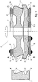
- FIG. 1 an inventive notching tool with a tool body 2 and associated workpiece 7 in four variants A, B, C, D of the invention is shown greatly simplified.
- the variants A, B, C, D shown here are modeled on a tool body 2 for reasons of illustration. All illustrated variants A, B, C, D effect the same machining of the workpiece 7.
- the notching tool is designed as a rotary working tool.
- the tool body 2 is composed of a plurality of basic bodies 1, which are pushed concentrically to each other on a driven shaft and rotate with it, wherein they are preferably releasably connected to the shaft.
- the tool body 2 has, on an outer surface facing the workpiece 7, a first processing region 3 with geometrically indefinite cutting edges 5 and a second processing region 4 with geometrically determined cutting 6.
- the first processing area 3 latches out of the workpiece 7 a first contour area 3 '
- the second processing area latches out of the workpiece 7 a second contour area 4'.
- the second contour region 4 ' is formed in the illustrated case by two outer chamfers.
- All four illustrated variants A, B, C, D show an insert 8, which in each case has at least one geometrically determined cutting edge 6, which forms the second processing region 4 and unlatches the second contour region 4 'from the workpiece 7.
- a plurality of geometrically determined cutting edges 6 are distributed over the circumference of the tool body 2 in the second processing region 4.
- the cutting plate geometrically defined cutting 6 for both directions of rotation, ie with opposite intended cutting directions have.
- Variant A shows a cutting plate 8, which is connected to one of the base body 1, wherein the base body 1, which carries the cutting plate 8, at the same time forms a part of the first processing area 3.
- the cutting plate 8 is preferably designed as an indexable insert, which is detachably mounted on the base body 1.
- a plurality of such cutting plates 8 are arranged at regular intervals over the circumference of the main body 1.
- the cutting plate 8 is preferably mounted directly on the base body 1 via a screw connection or indirectly via a cutting plate carrier.
- the cutting plate 8 is formed by a single annular element that is connected to one of the base body 1 and at least one of its circumference geometrically has certain cutting edge 6, which forms the second processing area 4. Again, the cutting plate 8 is connected to one of the base body 1, which form at least a part of the first processing area 3 on an outer surface facing the workpiece 7.
- Variant C represents a cutting plate 8 which is connected to a base body 1 which is pushed onto the shaft concentrically with respect to the other base bodies 1, is releasably connected to the shaft and rotates with this and the other basic bodies 1.
- the cutting plate 8 is preferably formed in variant C of an annular element.
- the connection between the cutting plate 8 and the base body 1 is preferably carried out as a permanent connection, which in particular includes soldering or welding connections, but also a shrinking of the annular cutting plate 8 on the base body is conceivable.
- the last illustrated variant D shows similar to the variant C, a cutting plate 8, which is executed in variant D, however, in one piece with the base body 1.
- Base body 1 and insert 8 thus form a unit.
Description
- Die Erfindung betrifft ein Ausklinkwerkzeug, insbesondere zur Bearbeitung von Kunststoff- oder Aluminiumprofilen, gemäß dem Oberbegriff des Anspruchs 1. Ein solches Ausklinkwerkzeug ist aus
DE 202 18 724 U bekannt. Aus derEP 1 422 005 A1 ist ein Verfahren und eine Vorrichtung zur Randbearbeitung einer optischen Linse aus Kunststoff sowie ein Kombinationswerkzeug dafür bekannt. Das Kombinationswerkzeug weist verschiedene Bearbeitungsbereiche auf, mittels derer in unterschiedlichen Arbeitsgängen eine Randbearbeitung, insbesondere von Kunststoff-Brillenlinsen, erfolgen kann. Als Ausklinkwerkzeug im Sinne der vorliegenden Patentanmeldung ist das Kombinationswerkzeug entsprechend der europäischen Patentanmeldung nicht einsetzbar. Die DruckschriftDE 102 55 058 A1 ist die prioritätsbegründende deutsche Patentanmeldung zu der vorher genannten europäischen Patentanmeldung. Inhaltlich sind beide Druckschriften deckungsgleich. - Die Druckschrift
DE 35 42 258 zeigt ein Werkzeug für die spanabhebende Bearbeitung, vorzugsweise als Fräs- und Schleifwerkzeug. Das Fräs- bzw. Schleifwerkzeug ist dabei in der Lage in einem Arbeitsgang gleichzeitig zu fräsen und zu schleifen. Das Werkzeug besteht dabei aus einer in Bearbeitungsrichtung vorn angeordneten Schneidplatte sowie einer sich direkt dahinter befindlichen Stützplatte. Bezogen auf den Durchmesser des abzuhebenden Spanes ist die Stützplatte im Durchmesser gegenüber der Schneidkontur der Schneidplatte leicht überstehend, so dass sie der gleichen Kontur der Schneidplatte folgend lediglich das Schleifen übernimmt. - Aus der Druckschrift
DE 695 11 198 T2 ist eine kombinierte Vorrichtung zum Randbearbeiten und Polieren und Sicherheitsfasen von Linsen sowie ein entsprechendes Werkzeug dafür und seiner Verwendung beschrieben. Mittels des in dieser Druckschrift vorgestellten Werkzeuges ist es möglich, beispielsweise fasen- oder nutenartige Vertiefungen oder entsprechend keilförmig ausgebildete Fasen, beispielsweise zur Befestigung der Brillengläser in einem Gestell, herzustellen. Allerdings muß dazu entweder das Werkzeug oder das zu bearbeitende Werkstück jeweils neu positioniert werden, um die jeweilige Bearbeitungsaufgabe durchführen zu können. Ausklinkwerkzeuge ähnlicher Art sind aus derDE 202 18 724 U1 bekannt. Hierin wird ein rotatorisch arbeitendes Ausklinkwerkzeug offenbart, dessen Profil erzeugende Oberfläche mit Diamanten besetzt ist, um eine möglichst hohe Fertigungsgüte zu erzielen und die Werkzeugstandzeiten bei gleichzeitiger Verringerung der Bearbeitungszeit zu erhöhen. Jedoch trägt die Bearbeitung vor allem von Kunststoffprofilen durch mit Diamanten besetzte Schleifkörper nicht allen Anforderungen an eine möglichst hohe Fertigungsgüte Rechnung. Es hat sich nämlich gezeigt, dass diese Form der Bearbeitung, insbesondere bei der Fasenbearbeitung, zu nicht befriedigenden Ergebnissen führt, da es zu einem Fasenbrechen durch die Verwendung von Diamantwerkzeugen kommen kann. - Dokument
US 3 898 772 A offenbart ein einstückiges Werkzeug zur Schleif- oder Trennbearbeitung mit an einem Grundkörper angeordneten Schneiden. Dieses Werkzeug erlaubt lediglich die Bearbeitung von Werkzeugen, nicht jedoch die Ausbildung unterschiedlicher Konturen. - Es ist daher Aufgabe der Erfindung ein Ausklinkwerkzeug entsprechend des Oberbegriffs des Anspruchs 1 zu schaffen, welches durch entsprechende Gestaltung des Werkzeugkörpers jeden zu bearbeitenden Konturbereich mit einem für diesen Bereich optimierten Bearbeitungsverfahren zu bearbeiten vermag.
- Diese Aufgabe wird nach der Erfindung durch die Merkmale des Anspruchs 1 gelöst. Hierdurch werden die Vorteile einer Bearbeitung durch einen Werkzeugkörper mit unbestimmten Schneiden mit denen einer Bearbeitung durch Werkzeugkörper mit bestimmten Schneiden verknüpft, so dass jeder zu bearbeitende Konturbereich einen mit einem optimalen Fertigungsverfahren bearbeitet wird.
- Diese spanenden Fertigungsverfahren sind allgemein dem Trennen zuzuordnen. Dabei umfasst das Spanen mit geometrisch unbestimmten Schneiden insbesondere das Schleifen, das Spanen mit geometrisch bestimmter Schneide umfasst hingegen unter anderem das Drehen, Fräsen, Hobeln, Stoßen und Räumen.
- Gegenüber allen aus dem Stand der Technik bekannten Lösungen zeichnet sich die Erfindung insbesondere dadurch aus, dass mittels des Ausklinkwerkzeuges Kunststoffprofile insbesondere in einem Arbeitsgang hinsichtlich der Bearbeitung mit bestimmten und unbestimmten Schneiden erfolgen kann. Dabei können unterschiedlichste Konturen, insbesondere an Kunststoffprofilen, erhalten werden, wenn das Ausklinkwerkzeug entsprechend ausgebildet ist. Dazu ist es möglich, das Ausklinkwerkzeug entweder entsprechend der gewünschten Kontur zu gestalten. Es ist allerdings auch möglich, entsprechend einer vorteilhaften Weiterbildung der Erfindung, dieses an unterschiedliche Konturen anpassbar zu gestalten. Damit werden unterschiedlichste Konturenverläufe an Werkstücken in einem einzigen Arbeitsgang hergestellt. Alle aus dem Stand der Technik bekannten Werkzeuge können dies nicht in einem Arbeitsgang. Entweder ist es nicht möglich, unterschiedliche Konturen zu erhalten oder aber es ist notwendig, das Werkzeug bzw. das Werkstück für den jeweiligen Bearbeitungsgang neu einzurichten, um die gewünschte Bearbeitung durchführen zu können. Dies erfordert einen nicht unerheblichen Zeitaufwand. Dieser wird durch die Erfindung jetzt eingespart.
- Um beide Arten der spanenden Bearbeitung gut kombinieren zu können, bietet sich an, dass der Werkzeugkörper von mehreren, konzentrisch zueinander angeordneten Grundkörpern gebildet ist, die auf einer angetriebenen Welle angeordnet sind und mit dieser rotieren. Der Werkzeugkörper kombiniert also in diesem Fall die Verfahren Schleifen (geometrisch unbestimmte Schneide) und Fräsen (geometrisch bestimmte Schneide) miteinander. Ferner bietet diese Art des Werkzeugaufbaus Vorteile für eine schnelle Reparatur des Werkzeugkörpers und die Möglichkeit, den Werkzeugkörper der herzustellenden Kontur durch Auswechslung von unterschiedlichen Grundkörpern mit verschieden geformten Bearbeitungsbereichen anzupassen. Zweckmäßiger Weise sind die Grundkörper hierzu lösbar mit der Welle verbunden, sie können aber, sofern dies vorteilhaft erscheint, auch einstückig mit der Welle verbunden sein.
- Der erste Bearbeitungsbereich ist erfindungsgemäß von einer mit Diamanten besetzten, dem Werkstück zugewandten Außenfläche des Werkzeugkörpers gebildet. Die Bearbeitung mit Diamanten führt zu einer guten Fertigungsgüte und gewährleistet gleichzeitig hohe Werkzeugstandzeiten und eine zügige Bearbeitung des Werkstücks.
- Der zweite Bearbeitungsbereich ist von zumindest einer vorzugsweise aus Hartmetall hergestellten Schneidplatte gebildet, die wenigstens eine geometrisch bestimmten Schneide aufweist. Schneidplatten aus Werkzeug- oder Schnellarbeitsstählen, aus Schneidkeramiken oder polykristallinen Schneidstoffen können in bestimmten Fällen ebenfalls vorteilhaft sein.
- Ein weiterer Aspekt der Erfindung ist dadurch angegeben, dass der erste Bearbeitungsbereich und der zweite Bearbeitungsbereich derart ausgebildet sind, dass sie an unterschiedlich gewünschte Konturen eines Werkstückes anpassbar sind, insbesondere derart, dass die Bearbeitung des Werkstückes in einem Arbeitsgang ermöglicht ist. So ist es beispielsweise möglich, das Ausklinkwerkzeug so zu gestalten, dass bestimmte Bereiche verstellbar bzw. veränderbar ausgebildet sind. Dies kann zum einen im Durchmesser, dies kann aber auch in der Höhe geschehen. Beispielsweise können Zwischenstücke vorgesehen sein, die zur Erreichung einer bestimmten Kontur vor der Bearbeitung zugefügt werden. Im weiteren ist auch eine Verstellung der Anstellwinkel der Schneiden vorgesehen, so dass unterschiedlichste Varianten realisierbar sind. Dies vermögen die aus dem Stand der Technik bekannten Lösungen von Kombinationswerkzeugen der Kunststoffbearbeitung nicht zu leisten. Vielmehr besitzen diese gegenüber der jetzt vorgestellten verbesserten Variante der Erfindung feste, nicht verstellbare Schneidbereiche bzw. Schleifbereiche.
- Es kann vorgesehen sein, dass zumindest einer der Grundkörper von einer Schneidplatte gebildet ist. In diesem Fall sind die Schneidplatte und einer der Grundkörper einstückig ausgeführt. Die Schneidplatte kann so in besonderes einfacher Weise auf die Welle aufgeschoben werden und als Teil des Werkzeugkörpers den zweiten Bearbeitungsbereich bilden.
- Eine alternative Ausgestaltung des erfindungsgemäßen Ausklinkwerkzeugs sieht vor, dass die Schneidplatten mit einem der Grundkörper lösbar oder unlösbar verbunden sind. Die Schneidplatten werden bei einer unlösbaren Verbindung mit einem der Grundkörper vorzugsweise verlötet, verschweißt oder aufgeschrumpft. Sind die Schneidplatten mit einem Grundkörper lösbar verbunden, sind sie in der Regel verschraubt. So kann der Werkzeugkörper für den jeweiligen Anwendungsfall optimiert aufgebaut werden. Eine solche Ausgestaltung hat ferner den Vorteil, dass bei einer Beschädigung einer geometrisch bestimmten Schneide diese durch Austausch der Schneidplatte schnell und einfach ersetzt werden kann. Ferner kann, sofern die Form des zweiten Konturbereichs geändert werden soll, der Werkzeugkörper der neuen Kontur durch Austausch einer Schneidplatte in effizienter Weise angepasst werden.
- Eine Weiterbildung der Erfindung zeichnet sich dadurch aus, dass die Schneidplatte eine Wendeschneidplatte ist, die mit einem der Grundkörper lösbar verbunden ist. Die Verwendung von Wendeschneidplatten ist zum Einen preiswert und ermöglicht zum Anderen eine schnelle und einfache Anpassung des Werkzeugkörpers, insbesondere bei Beschädigungen einer geometrisch bestimmten Schneide.
- Sofern die Schneidplatte lösbar mit einem der Grundkörper verbunden ist, ist es vorteilhaft, dass die Schneidplatte über eine lösbare Arretierung an einem der Grundkörper befestigt ist und relativ zum Grundkörper verschiebbar, versetzbar oder verdrehbar gelagert ist. So wird eine Einstellbarkeit der einzelnen Schneidplatten und somit der geometrisch bestimmten Schneiden am Grundkörper ermöglicht. Hierdurch wird in besonders einfacher und vorteilhafter Weise erreicht, dass eine Modifizierung des Werkzeugkörpers zwecks einer Änderung des zweiten Konturbereichs lediglich durch Lösen einer Schneidplatte, Verstellen der Schneidplatte relativ zum Grundkörper und wieder Feststellen der Schneidplatte realisiert werden kann. Beispielsweise kann eine Änderung eines durch die Schneidplatte am Werkstück bewirkten Fasenwinkels oder einer Konturtiefe oder -form so realisiert werden, ohne dabei einen Grundkörper von der Welle abnehmen zu müssen. Die Verstellbarkeit kann etwa durch mehrere zueinander versetzte Bohrungen oder durch Langlöcher in der Schneidplatte realisiert werden.
- Um eine besonders zügige und günstige Bearbeitung des Werkstücks zu ermöglichen, ist vorgesehen, dass zumindest zwei geometrisch bestimmte Schneiden für zumindest einen Teil des zweiten Bearbeitungsbereichs vorgesehen sind, deren jeweilige bestimmungsgemäße Schnittrichtung entgegensetzt sind. Eine Bearbeitung des Werkstücks mit dem ersten Bearbeitungsbereich ist durch dessen Ausgestaltung mit geometrisch unbestimmten Schneiden problemlos in mehreren Richtungen möglich. Daher ist es wünschenswert, dass auch der zweite Bearbeitungsbereich, beispielsweise bei einer Bearbeitung mit einem rotatorisch arbeitenden Ausklinkwerkzeug, derart ausgestaltet ist, dass mit ihm sowohl eine linksdrehende als auch eine rechtsdrehende Bearbeitung möglich ist. Die geometrisch bestimmten Schneiden mit entgegensetzten bestimmungsgemäßen Schnittrichtungen können dabei zum Beispiel auf einer Schneidplatte angeordnet sein, oder sie sind etwa in Form von entgegensetzt ausgerichteten Wendeschneidplatten lösbar oder unlösbar mit einem der Grundkörper verbunden.
- Grundsätzlich sei angeführt, dass eine Schneidplatte selbstverständlich auch mehrteilig ausgeführt sein kann. So ist im Sinne der Erfindung beispielsweise auch ein Träger mit einer an diesem angeordneten und befestigten Wendeschneidplatte, wie es etwa bei Drehmeißeln üblich ist, unter dem Begriff Schneidplatte zusammenzufassen.
- Weitere Merkmale und Vorteile der Erfindung ergeben sich aus den Unteransprüchen und aus der nachfolgenden Beschreibung bevorzugter Ausführungsbeispiele anhand der Zeichnung.
- In der Zeichnung zeigt:
- Fig. 1
- ein erfindungsgemäßes Ausklinkwerkzeug mit einem Werkzeugkörper in vier möglichen Varianten A, B, C, D in stark vereinfachter Darstellung.
- In
Figur 1 ist ein erfindungsgemäßes Ausklinkwerkzeug mit einem Werkzeugkörper 2 und zugehörigem Werkstück 7 in vier Varianten A, B, C, D der Erfindung stark vereinfacht dargestellt. Die gezeigten Varianten A, B, C, D sind hier aus Gründen der Veranschaulichung modellhaft an einem Werkzeugkörper 2 dargestellt. Alle dargestellten Varianten A, B, C, D bewirken die gleiche Bearbeitung des Werkstücks 7. - Hier ist das Ausklinkwerkzeug als rotatorisch arbeitendes Werkzeug ausgeführt. Der Werkzeugkörper 2 ist aus mehreren Grundkörpern 1 aufgebaut, die konzentrisch zueinander auf eine angetriebene Welle aufgeschoben werden und mit ihr rotieren, wobei sie vorzugsweise lösbar mit der Welle verbunden sind. Der Werkzeugkörper 2 weist auf einer dem Werkstück 7 zugewandten Außenfläche einen ersten Bearbeitungsbereich 3 mit geometrisch unbestimmten Schneiden 5 und einen zweiten Bearbeitungsbereich 4 mit geometrisch bestimmten Schneiden 6 auf. Der erste Bearbeitungsbereich 3 klinkt dabei aus dem Werkstück 7 einen ersten Konturbereich 3' aus, der zweite Bearbeitungsbereich klinkt aus dem Werkstück 7 einen zweiten Konturbereich 4' aus. Der zweite Konturbereich 4' ist in dem illustrierten Fall von zwei äußeren Fasen gebildet.
- Alle vier dargestellten Varianten A, B, C, D zeigen eine Schneidplatte 8, die jeweils zumindest eine geometrisch bestimmte Schneide 6 aufweist, die den zweiten Bearbeitungsbereich 4 bildet und den zweiten Konturbereich 4' aus dem Werkstück 7 ausklinkt. In der Regel sind aber mehrere geometrisch bestimmte Schneiden 6 über den Umfang des Werkzeugkörpers 2 im zweiten Bearbeitungsbereich 4 verteilt. Um die Funktion des Ausklinkwerkzeugs von der Rotationsrichtung des Werkzeugkörpers 2 unabhängig zu machen, kann in einer vorteilhaften Weiterbildung der Erfindung die Schneidplatte geometrisch bestimmte Schneiden 6 für beide Rotationsrichtungen, also mit entgegengesetzten bestimmungsgemäßen Schnittrichtungen, aufweisen.
- Variante A zeigt eine Schneidplatte 8, die mit einem der Grundkörper 1 verbunden ist, wobei der Grundkörper 1, der die Schneidplatte 8 trägt, gleichzeitig auch einen Teil des ersten Bearbeitungsbereich 3 bildet. Die Schneidplatte 8 ist vorzugsweise als Wendeschneidplatte ausgeführt, die lösbar auf dem Grundkörper 1 angebracht ist. Vorzugsweise sind mehrere solcher Schneidplatten 8 in regelmäßigen Abständen über den Umfang des Grundkörpers 1 angeordnet. Die Schneidplatte 8 ist dabei vorzugsweise unmittelbar über ein Schraubenverbindung oder mittelbar über einen Schneidplattenträger auf dem Grundkörper 1 angebracht.
- Bei Variante B ist die Schneidplatte 8 von einem einzigen ringförmigen Element gebildet, dass mit einem der Grundkörper 1 verbunden ist und über seinen Umfang zumindest eine geometrisch bestimmte Schneide 6 aufweist, die den zweiten Bearbeitungsbereich 4 bildet. Auch hier ist die Schneidplatte 8 mit einem der Grundkörper 1 verbunden, die an einer dem Werkstück 7 zugewandten Außenfläche zumindest einen Teil des ersten Bearbeitungsbereichs 3 bilden.
- Variante C stellt eine Schneidplatte 8 dar, die mit einem Grundkörper 1 verbunden ist, der konzentrisch zu den anderen Grundkörpern 1 auf die Welle aufgeschoben wird, lösbar mit der Welle verbunden ist und mit dieser und den anderen Grundkörpern 1 rotiert. Die Schneidplatte 8 ist bei Variante C vorzugsweise von einem ringförmigen Element gebildet. Die Verbindung zwischen Schneidplatte 8 und Grundkörper 1 wird vorzugsweise als unlösbare Verbindung ausgeführt, was insbesondere Löt- oder Schweißverbindungen beinhaltet, jedoch ist auch ein Aufschrumpfen der ringförmigen Schneidplatte 8 auf den Grundkörper denkbar.
- Die letzte dargestellte Variante D zeigt ähnlich der Variante C eine Schneiplatte 8, wobei diese bei Variante D jedoch einstückig mit dem Grundkörper 1 ausgeführt ist. Grundkörper 1 und Schneidplatte 8 bilden also eine Einheit.
Claims (8)
- Ausklinkwerkzeug, insbesondere zur Bearbeitung von Kunststoff- oder Aluminiumprofilen, umfassend einen von mehreren Grundkörpern (1) gebildeten Werkzeugkörper (2), der zumindest einen ersten Bearbeitungsbereich (3) zum Ausklinken eines ersten Konturbereiches (3') und zumindest einen zweiten Bearbeitungsbereich (4) zum Ausklinken eines zweiten Konturbereiches (4') aufweist, wobei der erste Bearbeitungsbereich (3) geometrisch unbestimmte Schneiden (5) aufweist und der Werkzeugkörper (2) von mehreren konzentrisch zueinander angeordneten Grundkörpern (1) gebildet ist, die lösbar auf einer angetriebenen Welle angeordnet sind und mit dieser rotieren, dadurch gekennzeichnet, dass zumindest zwei geometrisch bestimmte Schneiden (6) für zumindest einen Teil des zweiten Bearbeitungsbereich (4) vorgesehen sind, deren jeweilige bestimmungsgemäße Schnittrichtung entgegensetzt ist.
- Ausklinkwerkzeug nach Anspruch 1, dadurch gekennzeichnet, dass der erste Bearbeitungsbereich (3) von einer mit Diamanten besetzten, dem Werkstück (7) zugewandten Außenfläche des Werkzeugkörpers (2) gebildet ist.
- Ausklinkwerkzeug nach einem oder mehreren der vorhergehenden Ansprüche, dadurch gekennzeichnet, dass der zweite Bearbeitungsbereich (4) von zumindest einer vorzugsweise aus Hartmetall hergestellten Schneidplatte (8) gebildet ist, die wenigstens eine geometrisch bestimmten Schneide (6) aufweist.
- Ausklinkwerkzeug nach einem oder mehreren der vorhergehenden Ansprüche, dadurch gekennzeichnet, dass der erste Bearbeitungsbereich (3) und der zweite Bearbeitungsbereich (4) derart ausgebildet sind, dass sie an unterschiedliche gewünschte Konturen eines Werkstückes (7) anpassbar sind, insbesondere derart, dass die Bearbeitung des Werkstückes (7) in einem Arbeitsgang ermöglicht ist.
- Ausklinkwerkzeug nach einem oder mehreren der vorhergehenden Ansprüche, dadurch gekennzeichnet, dass zumindest einer der Grundkörper (1) von einer Schneidplatte (8) gebildet ist.
- Ausklinkwerkzeug nach einem oder mehreren der vorhergehenden Ansprüche, dadurch gekennzeichnet, dass die Schneidplatten (8) mit einem der Grundkörper (1) lösbar oder unlösbar verbunden sind.
- Ausklinkwerkzeug nach einem oder mehreren der vorhergehenden Ansprüche, dadurch gekennzeichnet, dass die Schneidplatte (8) eine Wendeschneidplatte ist, die mit einem der Grundkörper (1) lösbar verbunden ist.
- Ausklinkwerkzeug nach einem oder mehreren der vorhergehenden Ansprüche, dadurch gekennzeichnet, dass die Schneidplatte (8) über eine lösbare Arretierung an einem der Grundkörper (1) befestigt ist und relativ zum Grundkörper (1) verschiebbar, versetzbar oder verdrehbar gelagert ist.
Priority Applications (2)
| Application Number | Priority Date | Filing Date | Title |
|---|---|---|---|
| SI200532221T SI1577060T1 (sl) | 2004-03-19 | 2005-03-18 | Zarezovalno orodje |
| PL05006044T PL1577060T3 (pl) | 2004-03-19 | 2005-03-18 | Narzędzie do obróbki krawędzi profili |
Applications Claiming Priority (2)
| Application Number | Priority Date | Filing Date | Title |
|---|---|---|---|
| DE202004004492U | 2004-03-19 | ||
| DE200420004492 DE202004004492U1 (de) | 2004-03-19 | 2004-03-19 | Ausklinkwerkzeug |
Publications (3)
| Publication Number | Publication Date |
|---|---|
| EP1577060A2 EP1577060A2 (de) | 2005-09-21 |
| EP1577060A3 EP1577060A3 (de) | 2006-04-12 |
| EP1577060B1 true EP1577060B1 (de) | 2018-05-16 |
Family
ID=34802099
Family Applications (1)
| Application Number | Title | Priority Date | Filing Date |
|---|---|---|---|
| EP05006044.1A Active EP1577060B1 (de) | 2004-03-19 | 2005-03-18 | Ausklinkwerkzeug |
Country Status (4)
| Country | Link |
|---|---|
| EP (1) | EP1577060B1 (de) |
| DE (1) | DE202004004492U1 (de) |
| PL (1) | PL1577060T3 (de) |
| SI (1) | SI1577060T1 (de) |
Families Citing this family (1)
| Publication number | Priority date | Publication date | Assignee | Title |
|---|---|---|---|---|
| DE202009014144U1 (de) | 2009-10-19 | 2011-03-03 | Mader, Gert | Ausklinkwerkzeug |
Citations (1)
| Publication number | Priority date | Publication date | Assignee | Title |
|---|---|---|---|---|
| DE20218724U1 (de) * | 2002-12-02 | 2003-03-13 | Leistner Werkzeugtechnik | Rotatorisch arbeitendes Ausklinkwerkzeug |
Family Cites Families (6)
| Publication number | Priority date | Publication date | Assignee | Title |
|---|---|---|---|---|
| DE2238387A1 (de) * | 1972-08-04 | 1974-03-28 | Winter & Sohn Ernst | Mehrschneidiges zerspanwerkzeug |
| US4171926A (en) * | 1978-04-21 | 1979-10-23 | American Optical Corporation | Lens cutter |
| DE3542258A1 (de) * | 1985-11-29 | 1987-06-04 | Howema Gmbh Wittenborn & Edel | Werkzeug fuer die spanabhebende bearbeitung, vorzugsweise fraes- und schleifwerkzeug |
| DE8629226U1 (de) * | 1986-11-03 | 1986-12-18 | Wernicke & Co Gmbh, 4000 Duesseldorf, De | |
| US5626511A (en) * | 1994-10-03 | 1997-05-06 | National Optronics, Inc. | Combination lens edger, polisher, and safety beveler, tool therefor and use thereof |
| DE10255058A1 (de) * | 2002-11-25 | 2004-06-17 | Loh Optikmaschinen Ag | Verfahren und Vorrichtung zur Randbearbeitung einer optischen Linse aus Kunststoff sowie Kombinationswerkzeug dafür |
-
2004
- 2004-03-19 DE DE200420004492 patent/DE202004004492U1/de not_active Expired - Lifetime
-
2005
- 2005-03-18 EP EP05006044.1A patent/EP1577060B1/de active Active
- 2005-03-18 SI SI200532221T patent/SI1577060T1/sl unknown
- 2005-03-18 PL PL05006044T patent/PL1577060T3/pl unknown
Patent Citations (1)
| Publication number | Priority date | Publication date | Assignee | Title |
|---|---|---|---|---|
| DE20218724U1 (de) * | 2002-12-02 | 2003-03-13 | Leistner Werkzeugtechnik | Rotatorisch arbeitendes Ausklinkwerkzeug |
Also Published As
| Publication number | Publication date |
|---|---|
| EP1577060A3 (de) | 2006-04-12 |
| DE202004004492U1 (de) | 2005-07-21 |
| EP1577060A2 (de) | 2005-09-21 |
| SI1577060T1 (sl) | 2018-10-30 |
| PL1577060T3 (pl) | 2018-10-31 |
Similar Documents
| Publication | Publication Date | Title |
|---|---|---|
| EP1317985B1 (de) | Werkzeug zur Feinstbearbeitung von Oberflächen | |
| EP1598137B1 (de) | Kegelrad-Verzahnmaschine zum Anfasen und/oder Entgraten eines Kegelrades und entsprechendes Verfahren | |
| DE3610016C2 (de) | ||
| EP1321210B1 (de) | Werkzeug | |
| EP2484471B1 (de) | Bearbeitungswerkzeug | |
| DE102005033920A1 (de) | Schneideinsatz, Werkzeug sowie Verfahren zur spanenden Bearbeitung eines Werkstücks | |
| EP1641585B1 (de) | Schneideinsatz | |
| EP1286802B1 (de) | Scheibenfräser | |
| DE19743971B4 (de) | Schneideinsatz, Fräswerkzeug und Verwendung des Fräswerkzeuges | |
| DE102005043842B4 (de) | Kugel- oder Torusfräser | |
| EP1283083B1 (de) | Frässchneideinsatz | |
| DE102007038935B4 (de) | Stabmesserkopf und entsprechende Werkzeugmaschine | |
| AT398049B (de) | Werkzeugträger zum wirbeln bzw. schälen von aussengewinden, schnecken und profilen | |
| DE10112165B4 (de) | Stabmesserkopf zum Verzahnen | |
| DE3432936A1 (de) | Entgratwerkzeug | |
| EP1577060B1 (de) | Ausklinkwerkzeug | |
| EP0841116B1 (de) | Verfahren zum Bearbeiten von rotationssymmetrischen Werkstückflächen sowie Werkzeug zur Durchführung eines solchen Verfahrens | |
| DE102017208017B4 (de) | Mehrschneidige Reibahle | |
| DE10333621B4 (de) | Schneideinsatz | |
| DE102004008166A1 (de) | Werkzeug zur spanenden Bearbeitung von Präzisionsbohrungen | |
| EP1281466B1 (de) | Werkzeug zur spanenden Bearbeitung | |
| DE3909643C2 (de) | Mehrschneidenwerkzeugkopf zur spanabhebenden Vor- und Feinbearbeitung mit kreisförmiger Schnittbewegung | |
| DE19934393B4 (de) | Kombiniertes Werkzeug zur Bearbeitung von rotationssymmetrischen Bohrungen in Werkstücken | |
| DE102017105032A1 (de) | Werkzeug, Maschine und Verfahren zum Erzeugen von dachfirstartigen Anspitzungen an Zähnen eines innen- und außenverzahnten Zahnrads | |
| DE3504296C2 (de) |
Legal Events
| Date | Code | Title | Description |
|---|---|---|---|
| PUAI | Public reference made under article 153(3) epc to a published international application that has entered the european phase |
Free format text: ORIGINAL CODE: 0009012 |
|
| AK | Designated contracting states |
Kind code of ref document: A2 Designated state(s): AT BE BG CH CY CZ DE DK EE ES FI FR GB GR HU IE IS IT LI LT LU MC NL PL PT RO SE SI SK TR |
|
| AX | Request for extension of the european patent |
Extension state: AL BA HR LV MK YU |
|
| PUAL | Search report despatched |
Free format text: ORIGINAL CODE: 0009013 |
|
| AK | Designated contracting states |
Kind code of ref document: A3 Designated state(s): AT BE BG CH CY CZ DE DK EE ES FI FR GB GR HU IE IS IT LI LT LU MC NL PL PT RO SE SI SK TR |
|
| AX | Request for extension of the european patent |
Extension state: AL BA HR LV MK YU |
|
| RIC1 | Information provided on ipc code assigned before grant |
Ipc: B24B 9/14 20060101ALI20060222BHEP Ipc: B24D 7/18 20060101AFI20050617BHEP Ipc: B23C 3/12 20060101ALI20060222BHEP |
|
| 17P | Request for examination filed |
Effective date: 20060926 |
|
| AKX | Designation fees paid |
Designated state(s): AT BE BG CH CY CZ DE DK EE ES FI FR GB GR HU IE IS IT LI LT LU MC NL PL PT RO SE SI SK TR |
|
| AXX | Extension fees paid |
Extension state: BA Payment date: 20060926 Extension state: LV Payment date: 20060926 Extension state: AL Payment date: 20060926 Extension state: MK Payment date: 20060926 Extension state: HR Payment date: 20060926 Extension state: YU Payment date: 20060926 |
|
| 17Q | First examination report despatched |
Effective date: 20141002 |
|
| STAA | Information on the status of an ep patent application or granted ep patent |
Free format text: STATUS: EXAMINATION IS IN PROGRESS |
|
| REG | Reference to a national code |
Ref country code: DE Ref legal event code: R079 Ref document number: 502005015825 Country of ref document: DE Free format text: PREVIOUS MAIN CLASS: B24D0007180000 Ipc: B23C0005080000 |
|
| GRAP | Despatch of communication of intention to grant a patent |
Free format text: ORIGINAL CODE: EPIDOSNIGR1 |
|
| STAA | Information on the status of an ep patent application or granted ep patent |
Free format text: STATUS: GRANT OF PATENT IS INTENDED |
|
| RIC1 | Information provided on ipc code assigned before grant |
Ipc: B23C 5/08 20060101AFI20170824BHEP Ipc: B24B 9/14 20060101ALI20170824BHEP Ipc: B23C 3/12 20060101ALI20170824BHEP Ipc: B24D 7/18 20060101ALI20170824BHEP |
|
| INTG | Intention to grant announced |
Effective date: 20170913 |
|
| GRAJ | Information related to disapproval of communication of intention to grant by the applicant or resumption of examination proceedings by the epo deleted |
Free format text: ORIGINAL CODE: EPIDOSDIGR1 |
|
| STAA | Information on the status of an ep patent application or granted ep patent |
Free format text: STATUS: EXAMINATION IS IN PROGRESS |
|
| GRAS | Grant fee paid |
Free format text: ORIGINAL CODE: EPIDOSNIGR3 |
|
| STAA | Information on the status of an ep patent application or granted ep patent |
Free format text: STATUS: GRANT OF PATENT IS INTENDED |
|
| GRAP | Despatch of communication of intention to grant a patent |
Free format text: ORIGINAL CODE: EPIDOSNIGR1 |
|
| INTC | Intention to grant announced (deleted) | ||
| INTG | Intention to grant announced |
Effective date: 20180129 |
|
| GRAA | (expected) grant |
Free format text: ORIGINAL CODE: 0009210 |
|
| STAA | Information on the status of an ep patent application or granted ep patent |
Free format text: STATUS: THE PATENT HAS BEEN GRANTED |
|
| AK | Designated contracting states |
Kind code of ref document: B1 Designated state(s): AT BE BG CH CY CZ DE DK EE ES FI FR GB GR HU IE IS IT LI LT LU MC NL PL PT RO SE SI SK TR |
|
| AX | Request for extension of the european patent |
Extension state: AL BA HR LV MK YU |
|
| REG | Reference to a national code |
Ref country code: GB Ref legal event code: FG4D Free format text: NOT ENGLISH |
|
| REG | Reference to a national code |
Ref country code: CH Ref legal event code: EP |
|
| REG | Reference to a national code |
Ref country code: DE Ref legal event code: R096 Ref document number: 502005015825 Country of ref document: DE |
|
| REG | Reference to a national code |
Ref country code: IE Ref legal event code: FG4D Free format text: LANGUAGE OF EP DOCUMENT: GERMAN |
|
| REG | Reference to a national code |
Ref country code: AT Ref legal event code: REF Ref document number: 999082 Country of ref document: AT Kind code of ref document: T Effective date: 20180615 |
|
| REG | Reference to a national code |
Ref country code: NL Ref legal event code: FP |
|
| REG | Reference to a national code |
Ref country code: LT Ref legal event code: MG4D |
|
| PG25 | Lapsed in a contracting state [announced via postgrant information from national office to epo] |
Ref country code: ES Free format text: LAPSE BECAUSE OF FAILURE TO SUBMIT A TRANSLATION OF THE DESCRIPTION OR TO PAY THE FEE WITHIN THE PRESCRIBED TIME-LIMIT Effective date: 20180516 Ref country code: LT Free format text: LAPSE BECAUSE OF FAILURE TO SUBMIT A TRANSLATION OF THE DESCRIPTION OR TO PAY THE FEE WITHIN THE PRESCRIBED TIME-LIMIT Effective date: 20180516 Ref country code: SE Free format text: LAPSE BECAUSE OF FAILURE TO SUBMIT A TRANSLATION OF THE DESCRIPTION OR TO PAY THE FEE WITHIN THE PRESCRIBED TIME-LIMIT Effective date: 20180516 Ref country code: BG Free format text: LAPSE BECAUSE OF FAILURE TO SUBMIT A TRANSLATION OF THE DESCRIPTION OR TO PAY THE FEE WITHIN THE PRESCRIBED TIME-LIMIT Effective date: 20180816 Ref country code: FI Free format text: LAPSE BECAUSE OF FAILURE TO SUBMIT A TRANSLATION OF THE DESCRIPTION OR TO PAY THE FEE WITHIN THE PRESCRIBED TIME-LIMIT Effective date: 20180516 |
|
| PG25 | Lapsed in a contracting state [announced via postgrant information from national office to epo] |
Ref country code: GR Free format text: LAPSE BECAUSE OF FAILURE TO SUBMIT A TRANSLATION OF THE DESCRIPTION OR TO PAY THE FEE WITHIN THE PRESCRIBED TIME-LIMIT Effective date: 20180817 |
|
| PG25 | Lapsed in a contracting state [announced via postgrant information from national office to epo] |
Ref country code: PT Free format text: LAPSE BECAUSE OF FAILURE TO SUBMIT A TRANSLATION OF THE DESCRIPTION OR TO PAY THE FEE WITHIN THE PRESCRIBED TIME-LIMIT Effective date: 20180917 |
|
| PG25 | Lapsed in a contracting state [announced via postgrant information from national office to epo] |
Ref country code: DK Free format text: LAPSE BECAUSE OF FAILURE TO SUBMIT A TRANSLATION OF THE DESCRIPTION OR TO PAY THE FEE WITHIN THE PRESCRIBED TIME-LIMIT Effective date: 20180516 Ref country code: SK Free format text: LAPSE BECAUSE OF FAILURE TO SUBMIT A TRANSLATION OF THE DESCRIPTION OR TO PAY THE FEE WITHIN THE PRESCRIBED TIME-LIMIT Effective date: 20180516 Ref country code: CZ Free format text: LAPSE BECAUSE OF FAILURE TO SUBMIT A TRANSLATION OF THE DESCRIPTION OR TO PAY THE FEE WITHIN THE PRESCRIBED TIME-LIMIT Effective date: 20180516 Ref country code: RO Free format text: LAPSE BECAUSE OF FAILURE TO SUBMIT A TRANSLATION OF THE DESCRIPTION OR TO PAY THE FEE WITHIN THE PRESCRIBED TIME-LIMIT Effective date: 20180516 Ref country code: EE Free format text: LAPSE BECAUSE OF FAILURE TO SUBMIT A TRANSLATION OF THE DESCRIPTION OR TO PAY THE FEE WITHIN THE PRESCRIBED TIME-LIMIT Effective date: 20180516 |
|
| REG | Reference to a national code |
Ref country code: CH Ref legal event code: PK Free format text: BERICHTIGUNGEN |
|
| RIC2 | Information provided on ipc code assigned after grant |
Ipc: B23C 5/08 20060101AFI20170824BHEP Ipc: B23C 3/12 20060101ALI20170824BHEP Ipc: B24D 7/18 20060101ALI20170824BHEP Ipc: B24B 9/14 20060101ALI20170824BHEP |
|
| REG | Reference to a national code |
Ref country code: DE Ref legal event code: R097 Ref document number: 502005015825 Country of ref document: DE |
|
| PG25 | Lapsed in a contracting state [announced via postgrant information from national office to epo] |
Ref country code: IT Free format text: LAPSE BECAUSE OF FAILURE TO SUBMIT A TRANSLATION OF THE DESCRIPTION OR TO PAY THE FEE WITHIN THE PRESCRIBED TIME-LIMIT Effective date: 20180516 |
|
| PLBE | No opposition filed within time limit |
Free format text: ORIGINAL CODE: 0009261 |
|
| STAA | Information on the status of an ep patent application or granted ep patent |
Free format text: STATUS: NO OPPOSITION FILED WITHIN TIME LIMIT |
|
| 26N | No opposition filed |
Effective date: 20190219 |
|
| REG | Reference to a national code |
Ref country code: DE Ref legal event code: R082 Ref document number: 502005015825 Country of ref document: DE Representative=s name: PATENTANWAELTE OLBRICHT, BUCHHOLD, KEULERTZ PA, DE |
|
| PG25 | Lapsed in a contracting state [announced via postgrant information from national office to epo] |
Ref country code: MC Free format text: LAPSE BECAUSE OF FAILURE TO SUBMIT A TRANSLATION OF THE DESCRIPTION OR TO PAY THE FEE WITHIN THE PRESCRIBED TIME-LIMIT Effective date: 20180516 |
|
| REG | Reference to a national code |
Ref country code: CH Ref legal event code: PL |
|
| GBPC | Gb: european patent ceased through non-payment of renewal fee |
Effective date: 20190318 |
|
| PG25 | Lapsed in a contracting state [announced via postgrant information from national office to epo] |
Ref country code: LU Free format text: LAPSE BECAUSE OF NON-PAYMENT OF DUE FEES Effective date: 20190318 |
|
| PG25 | Lapsed in a contracting state [announced via postgrant information from national office to epo] |
Ref country code: GB Free format text: LAPSE BECAUSE OF NON-PAYMENT OF DUE FEES Effective date: 20190318 Ref country code: LI Free format text: LAPSE BECAUSE OF NON-PAYMENT OF DUE FEES Effective date: 20190331 Ref country code: CH Free format text: LAPSE BECAUSE OF NON-PAYMENT OF DUE FEES Effective date: 20190331 Ref country code: IE Free format text: LAPSE BECAUSE OF NON-PAYMENT OF DUE FEES Effective date: 20190318 |
|
| PG25 | Lapsed in a contracting state [announced via postgrant information from national office to epo] |
Ref country code: FR Free format text: LAPSE BECAUSE OF NON-PAYMENT OF DUE FEES Effective date: 20190331 |
|
| PG25 | Lapsed in a contracting state [announced via postgrant information from national office to epo] |
Ref country code: TR Free format text: LAPSE BECAUSE OF FAILURE TO SUBMIT A TRANSLATION OF THE DESCRIPTION OR TO PAY THE FEE WITHIN THE PRESCRIBED TIME-LIMIT Effective date: 20180516 |
|
| REG | Reference to a national code |
Ref country code: AT Ref legal event code: MM01 Ref document number: 999082 Country of ref document: AT Kind code of ref document: T Effective date: 20190318 |
|
| PG25 | Lapsed in a contracting state [announced via postgrant information from national office to epo] |
Ref country code: AT Free format text: LAPSE BECAUSE OF NON-PAYMENT OF DUE FEES Effective date: 20190318 |
|
| PG25 | Lapsed in a contracting state [announced via postgrant information from national office to epo] |
Ref country code: CY Free format text: LAPSE BECAUSE OF FAILURE TO SUBMIT A TRANSLATION OF THE DESCRIPTION OR TO PAY THE FEE WITHIN THE PRESCRIBED TIME-LIMIT Effective date: 20180516 |
|
| PG25 | Lapsed in a contracting state [announced via postgrant information from national office to epo] |
Ref country code: IS Free format text: LAPSE BECAUSE OF FAILURE TO SUBMIT A TRANSLATION OF THE DESCRIPTION OR TO PAY THE FEE WITHIN THE PRESCRIBED TIME-LIMIT Effective date: 20180916 |
|
| PG25 | Lapsed in a contracting state [announced via postgrant information from national office to epo] |
Ref country code: HU Free format text: LAPSE BECAUSE OF FAILURE TO SUBMIT A TRANSLATION OF THE DESCRIPTION OR TO PAY THE FEE WITHIN THE PRESCRIBED TIME-LIMIT; INVALID AB INITIO Effective date: 20050318 |
|
| REG | Reference to a national code |
Ref country code: DE Ref legal event code: R082 Ref document number: 502005015825 Country of ref document: DE Representative=s name: PATENTANWAELTE OLBRICHT, BUCHHOLD, KEULERTZ PA, DE |
|
| PGFP | Annual fee paid to national office [announced via postgrant information from national office to epo] |
Ref country code: SI Payment date: 20230316 Year of fee payment: 19 Ref country code: PL Payment date: 20230316 Year of fee payment: 19 Ref country code: DE Payment date: 20230331 Year of fee payment: 19 Ref country code: BE Payment date: 20230321 Year of fee payment: 19 |
|
| PGFP | Annual fee paid to national office [announced via postgrant information from national office to epo] |
Ref country code: NL Payment date: 20230321 Year of fee payment: 19 |