EP2004354B1 - Porte-lames et tête de fraisage - Google Patents
Porte-lames et tête de fraisage Download PDFInfo
- Publication number
- EP2004354B1 EP2004354B1 EP07722190A EP07722190A EP2004354B1 EP 2004354 B1 EP2004354 B1 EP 2004354B1 EP 07722190 A EP07722190 A EP 07722190A EP 07722190 A EP07722190 A EP 07722190A EP 2004354 B1 EP2004354 B1 EP 2004354B1
- Authority
- EP
- European Patent Office
- Prior art keywords
- cutter
- support according
- bevel
- cutter support
- cutting edge
- Prior art date
- Legal status (The legal status is an assumption and is not a legal conclusion. Google has not performed a legal analysis and makes no representation as to the accuracy of the status listed.)
- Not-in-force
Links
Images

Classifications
-
- B—PERFORMING OPERATIONS; TRANSPORTING
- B23—MACHINE TOOLS; METAL-WORKING NOT OTHERWISE PROVIDED FOR
- B23C—MILLING
- B23C5/00—Milling-cutters
- B23C5/16—Milling-cutters characterised by physical features other than shape
- B23C5/20—Milling-cutters characterised by physical features other than shape with removable cutter bits or teeth or cutting inserts
- B23C5/22—Securing arrangements for bits or teeth or cutting inserts
- B23C5/24—Securing arrangements for bits or teeth or cutting inserts adjustable
- B23C5/2462—Securing arrangements for bits or teeth or cutting inserts adjustable the adjusting means being oblique surfaces
-
- B—PERFORMING OPERATIONS; TRANSPORTING
- B23—MACHINE TOOLS; METAL-WORKING NOT OTHERWISE PROVIDED FOR
- B23C—MILLING
- B23C5/00—Milling-cutters
- B23C5/02—Milling-cutters characterised by the shape of the cutter
- B23C5/10—Shank-type cutters, i.e. with an integral shaft
- B23C5/1081—Shank-type cutters, i.e. with an integral shaft with permanently fixed cutting inserts
-
- B—PERFORMING OPERATIONS; TRANSPORTING
- B23—MACHINE TOOLS; METAL-WORKING NOT OTHERWISE PROVIDED FOR
- B23C—MILLING
- B23C5/00—Milling-cutters
- B23C5/16—Milling-cutters characterised by physical features other than shape
- B23C5/18—Milling-cutters characterised by physical features other than shape with permanently-fixed cutter-bits or teeth
-
- B—PERFORMING OPERATIONS; TRANSPORTING
- B23—MACHINE TOOLS; METAL-WORKING NOT OTHERWISE PROVIDED FOR
- B23C—MILLING
- B23C5/00—Milling-cutters
- B23C5/16—Milling-cutters characterised by physical features other than shape
- B23C5/20—Milling-cutters characterised by physical features other than shape with removable cutter bits or teeth or cutting inserts
- B23C5/22—Securing arrangements for bits or teeth or cutting inserts
- B23C5/2265—Securing arrangements for bits or teeth or cutting inserts by means of a wedge
- B23C5/2278—Securing arrangements for bits or teeth or cutting inserts by means of a wedge for plate-like cutting inserts fitted on an intermediate carrier, e.g. shank fixed in the cutter body
-
- B—PERFORMING OPERATIONS; TRANSPORTING
- B23—MACHINE TOOLS; METAL-WORKING NOT OTHERWISE PROVIDED FOR
- B23C—MILLING
- B23C5/00—Milling-cutters
- B23C5/16—Milling-cutters characterised by physical features other than shape
- B23C5/20—Milling-cutters characterised by physical features other than shape with removable cutter bits or teeth or cutting inserts
- B23C5/22—Securing arrangements for bits or teeth or cutting inserts
- B23C5/24—Securing arrangements for bits or teeth or cutting inserts adjustable
- B23C5/2472—Securing arrangements for bits or teeth or cutting inserts adjustable the adjusting means being screws
-
- B—PERFORMING OPERATIONS; TRANSPORTING
- B23—MACHINE TOOLS; METAL-WORKING NOT OTHERWISE PROVIDED FOR
- B23C—MILLING
- B23C2215/00—Details of workpieces
- B23C2215/20—Crankshafts
-
- B—PERFORMING OPERATIONS; TRANSPORTING
- B23—MACHINE TOOLS; METAL-WORKING NOT OTHERWISE PROVIDED FOR
- B23C—MILLING
- B23C2226/00—Materials of tools or workpieces not comprising a metal
- B23C2226/12—Boron nitride
- B23C2226/125—Boron nitride cubic [CBN]
-
- B—PERFORMING OPERATIONS; TRANSPORTING
- B23—MACHINE TOOLS; METAL-WORKING NOT OTHERWISE PROVIDED FOR
- B23C—MILLING
- B23C2226/00—Materials of tools or workpieces not comprising a metal
- B23C2226/31—Diamond
- B23C2226/315—Diamond polycrystalline [PCD]
-
- B—PERFORMING OPERATIONS; TRANSPORTING
- B23—MACHINE TOOLS; METAL-WORKING NOT OTHERWISE PROVIDED FOR
- B23C—MILLING
- B23C2240/00—Details of connections of tools or workpieces
- B23C2240/08—Brazed connections
-
- B—PERFORMING OPERATIONS; TRANSPORTING
- B23—MACHINE TOOLS; METAL-WORKING NOT OTHERWISE PROVIDED FOR
- B23C—MILLING
- B23C2240/00—Details of connections of tools or workpieces
- B23C2240/16—Welded connections
-
- Y—GENERAL TAGGING OF NEW TECHNOLOGICAL DEVELOPMENTS; GENERAL TAGGING OF CROSS-SECTIONAL TECHNOLOGIES SPANNING OVER SEVERAL SECTIONS OF THE IPC; TECHNICAL SUBJECTS COVERED BY FORMER USPC CROSS-REFERENCE ART COLLECTIONS [XRACs] AND DIGESTS
- Y10—TECHNICAL SUBJECTS COVERED BY FORMER USPC
- Y10T—TECHNICAL SUBJECTS COVERED BY FORMER US CLASSIFICATION
- Y10T407/00—Cutters, for shaping
- Y10T407/19—Rotary cutting tool
- Y10T407/1906—Rotary cutting tool including holder [i.e., head] having seat for inserted tool
- Y10T407/1932—Rotary cutting tool including holder [i.e., head] having seat for inserted tool with means to fasten tool seat to holder
-
- Y—GENERAL TAGGING OF NEW TECHNOLOGICAL DEVELOPMENTS; GENERAL TAGGING OF CROSS-SECTIONAL TECHNOLOGIES SPANNING OVER SEVERAL SECTIONS OF THE IPC; TECHNICAL SUBJECTS COVERED BY FORMER USPC CROSS-REFERENCE ART COLLECTIONS [XRACs] AND DIGESTS
- Y10—TECHNICAL SUBJECTS COVERED BY FORMER USPC
- Y10T—TECHNICAL SUBJECTS COVERED BY FORMER US CLASSIFICATION
- Y10T407/00—Cutters, for shaping
- Y10T407/22—Cutters, for shaping including holder having seat for inserted tool
- Y10T407/2272—Cutters, for shaping including holder having seat for inserted tool with separate means to fasten tool to holder
- Y10T407/2282—Cutters, for shaping including holder having seat for inserted tool with separate means to fasten tool to holder including tool holding clamp and clamp actuator
- Y10T407/2284—Wedge clamp element
-
- Y—GENERAL TAGGING OF NEW TECHNOLOGICAL DEVELOPMENTS; GENERAL TAGGING OF CROSS-SECTIONAL TECHNOLOGIES SPANNING OVER SEVERAL SECTIONS OF THE IPC; TECHNICAL SUBJECTS COVERED BY FORMER USPC CROSS-REFERENCE ART COLLECTIONS [XRACs] AND DIGESTS
- Y10—TECHNICAL SUBJECTS COVERED BY FORMER USPC
- Y10T—TECHNICAL SUBJECTS COVERED BY FORMER US CLASSIFICATION
- Y10T409/00—Gear cutting, milling, or planing
- Y10T409/30—Milling
- Y10T409/30952—Milling with cutter holder
Definitions
- the invention relates to a blade carrier for attachment in a Fräsmesserkopf, consisting of a shaft-shaped pin and a head with soldered cutting edges with a side edge formed by a rake surface and an open space.
- the invention further relates to a Fräsmesserkopf with a plurality of cutting carriers used in recesses of a base body, are soldered to the respective cutting, the blade carriers are each axially adjustable via a wedge body and means-clamping elements in the Fräsmesserkopf fixable.
- the above-described Fräsmesserkopf is in principle from the DE 40 03 862 known.
- the recesses for the blade carrier extend in the blade head described there from the one end face of its base parallel to the axis of rotation and at a distance from the circumference, the cutting edges of the inserts used projecting only slightly beyond the end face of the base body.
- the axis of the serving for bracing round wedges each skewed to the axes of the cutting plates supporting cutting plate carrier.
- another round wedge with differential screw for axial adjustment of each cutting plate is provided and arranged in a recess which extends radially inwardly from the circumference of the base body. For axial adjustment and radially outward bracing geometrically equal round wedges are used.
- this cutter head As an advantage of this cutter head is highlighted that due to the position of the cutting plate carrier receiving recesses parallel to the axis of rotation of the body only radially directed centrifugal forces occur without axial components. These forces can be well intercepted, because the recesses are not located directly on the circumference of the body, but radially inwardly at a distance from the circumference.
- the knife head is therefore also suitable for extremely high speeds and the centrifugal forces occurring then.
- a fine adjustment of the cutting elements in the axial direction without interference with radial components is possible.
- crankshafts for cars have been subjected to finish machining by grinding or belt grinding, wherein the grinding has been carried out by the use of cooling lubricants, with the development of suitable milling tools, the grinding of the crankshafts could be replaced by milling processes.
- an orthogonal rotary milling with eccentric tool adjustment without axial feed is used.
- the tool executes a lowering movement, due to which the shape design of the bearing seats is generated exclusively by the tool cutting edge.
- the tool must be adjusted to the workpiece so that it is ensured that during the engagement of the minor cutting the entire apex line of the bearing seat is covered.
- the bearing seat diameter to be manufactured is generated via this vertex line. Due to the process, middle regions of the secondary cutting edge are engaged longer than other regions. This causes the cutting edge in the middle area to show a higher level of wear than in the outer areas.
- orthogonal rotary milling with eccentric tool adjustment without axial feed has a decisive disadvantage. Due to the fact that the tool cutting edge carries out a lowering operation in this method, the smallest cutting errors or the tool wear immediately have a negative effect on the shape and surface quality to be achieved. In particular, the different forms of tool wear leads to an earlier form deviation.
- the former object is achieved by a blade carrier according to claim 1.
- the blade carrier has a chamfer adjacent to the secondary cutting edge and arranged on the free surface, with a chamfer width decreasing outwards to 0 in each case. Further embodiments of the blade carrier are described in the subclaims.
- a Fräsmesserkopf according to claim 10 which is characterized by three blade carrier, which are arranged in equidistant angular distance from each other.
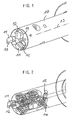
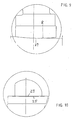
- the in Fig. 1 to 3 Milling cutter head shown essentially consists of a base body 10, in which three blade carrier 11 are soldered with each soldered cutting 12.
- the blade carriers 11 are each arranged in parallel to the longitudinal axis 13 holes 22 (see Fig. 3 ) used.
- Further bores in the main body 10 are provided substantially in the radial direction or slightly inclined thereto, in which wedge bodies 14 are arranged, which are displaceable in the radial direction via an adjusting screw 15, preferably a double-threaded screw.
- the wedge body 14 have wedge surfaces 16 which extend obliquely to the radial plane of the base body, so that during a radial movement of the wedge body 14 of the blade carrier 11 along its longitudinal axis, ie in the axial direction, is displaceable.
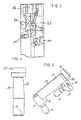
- the clamping piece 18 which is centrally located and has three clamping surfaces 19, which bear against corresponding clamping surfaces of the blade carrier 11.
- the clamping piece 18 can be fixed by means of a screw 21, which is preferably designed as a double-threaded screw.
- the clamping piece 18 is used in the illustrated case for the fixation of three blade carriers 11, each having a flat surface 20.
- each blade carrier 11 can be adjusted axially via a circular wedge and the associated screw 15. For the axis-parallel alignment of the blade carrier and thus the cutting serve the holes 22.
- the surface 23 serves to ensure that there is no line contact between the blade carrier 11 and bore 22.
- the cutter support 11 also has an inclined surface 24, the inclination of which corresponds to the inclination of a surface 19 of the clamping piece.
- Fig. 7 . 9 and 10 show enlarged views of the cutting edges;
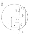
- Fig. 8 shows an optional embodiment in which the inner and the outer cutting area are angled relative to the central cutting area.
- the chamfer 29 serving as Vorverschl fashionfase has the task to emulate the characteristic of the process wear pattern, taking into account the required concave inwardly extending cutting fall.
- the degressive wear process is shortened.
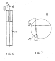
- the free surface of the cutting edge 25 while maintaining the clearance angle is ground either roof-shaped (for large radii and short cutting lengths) or as in Fig. 9 shown convexly ground under a radius R, which is preferably about 900 mm.
- Fig. 9 By training after Fig. 9 results in a distance of the highest point 27 of the cutting edge from the lowest point of 4 microns. If a bevel 29 is ground on the free surface 28 in a second operation, wherein the camber angle of the cutting edge is maintained, resulting in Fig. 10 illustrated embodiment of the bevel, which has approximately the middle of the cutting edge 25, the largest width of 4 microns.
- the chamfer extends to the ends of the cutting edge 25 and to a short-term location, wherein the chamfer 29 runs continuously narrower to a width of 0 mm on both sides. The chamfer thus results from a tendon-like section of a roof-shaped or convex free surface, which is arranged at a clearance angle of 10 °.
- the rake angle is uniformly 0 °.
- the cutting edges 12 are ground concave at a camber angle of 90 ° or a slightly smaller angle to the axis of rotation of the tool, resulting in the 4 ⁇ m increase in the point 27.
- a 5 ° angled secondary cutting part which is followed by a secondary cutting part 25b, which is perpendicular to the longitudinal axis 26 which is parallel to the axis of rotation 13, is arranged.
- a secondary cutting part 25c which is also inclined by 5 °.
Landscapes
- Engineering & Computer Science (AREA)
- Mechanical Engineering (AREA)
- Milling Processes (AREA)
- Shearing Machines (AREA)
- Knives (AREA)
Claims (10)
- Porte-lames pour la fixation dans une fraise à surfacer à lames amovibles, se composant d'une broche en forme de tige et d'une tête comprenant des lames brasées là-dedans qui présentent un tranchant secondaire (25) formé par une face de coupe et une face de dépouille, caractérisé par un chanfrein (29) contigu au tranchant secondaire (25) et disposé sur la face de dépouille et présentant une largeur de chanfrein qui diminue vers l'extérieur de manière à devenir respectivement 0.
- Porte-lames selon la revendication 1, caractérisé par le fait que ledit chanfrein (29) est disposé à peu près de manière centrale par rapport au tranchant secondaire (25).
- Porte-lames selon la revendication 1 ou 2, caractérisé par le fait que la largeur maximale du chanfrein est ≤ 10 µm, de préférence ≤ 4 µm.
- Porte-lames selon l'une quelconque des revendications 1 à 3, caractérisé par le fait que la largeur du chanfrein diminue continûment de part et d'autre de manière à devenir 0 µm, et/ou que le chanfrein (29) s'étend sur toute la largeur du tranchant secondaire.
- Porte-lames selon l'une quelconque des revendications 1 à 4, caractérisé par le fait que ledit chanfrein (29) est réalisé par deux opérations successives de rectification, à savoir par une première rectification de la zone de face de dépouille (28) contiguë au tranchant de manière à présenter donc une forme convexe ou une forme en toit et par une rectification partiellement plane subséquente de cette zone de face de dépouille.
- Porte-lames selon la revendication 5, caractérisé par le fait que le rayon de la zone de face de dépouille rectifiée de manière à présenter une forme convexe est R = 900 mm ± 100 mm.
- Porte-lames selon l'une quelconque des revendications 1 à 6, caractérisé par le fait que l'angle de dépouille est de 10° ± 2°.
- Porte-lames selon la revendication 5, caractérisé par un tranchant coudé, une portion centrale (25b) du tranchant étant perpendiculaire à l'axe longitudinal de la broche et les portions de tranchant (25a, 25c) y contiguës étant inclinées à un angle de ≤ 10°, de préférence de ≤ 5° par rapport à cela.
- Porte-lames selon la revendication 8, caractérisé par ie fait que le rapport de la longueur de la portion de tranchant inclinée (25a) située radialement à l'extérieur à la portion centrale de tranchant (25b) est de 2 à 3, et/ou que le rapport de la longueur de la portion de tranchant inclinée (25c) située radialement à l'intérieur à la portion de tranchant secondaire (25a) située radialement à l'extérieur est de 2 à 1.
- Fraise à surfacer à lames amovibles comprenant plusieurs porte-lames qui sont insérés dans des évidements d'un corps de base et sur chacun d'eux sont brasés des lames, lesdits porte-lames pouvant chacun être réglés axialement par l'intermédiaire d'un corps en forme de coin et être fixés au moyen d'éléments de serrage dans la fraise à surfacer à lames amovibles, caractérisée par deux porte-lames selon l'une quelconque des revendications 1 à 9 qui sont disposés l'un par rapport l'autre à un angle équidistant.
Priority Applications (1)
| Application Number | Priority Date | Filing Date | Title |
|---|---|---|---|
| PL07722190T PL2004354T3 (pl) | 2006-04-12 | 2007-04-11 | Oprawka noża składanego i głowica frezowa |
Applications Claiming Priority (2)
| Application Number | Priority Date | Filing Date | Title |
|---|---|---|---|
| DE202006006081U DE202006006081U1 (de) | 2006-04-12 | 2006-04-12 | Schneidenträger und Fräsmesserkopf |
| PCT/DE2007/000632 WO2007115561A1 (fr) | 2006-04-12 | 2007-04-11 | Porte-lames et tête de fraisage |
Publications (2)
| Publication Number | Publication Date |
|---|---|
| EP2004354A1 EP2004354A1 (fr) | 2008-12-24 |
| EP2004354B1 true EP2004354B1 (fr) | 2009-06-03 |
Family
ID=38370399
Family Applications (1)
| Application Number | Title | Priority Date | Filing Date |
|---|---|---|---|
| EP07722190A Not-in-force EP2004354B1 (fr) | 2006-04-12 | 2007-04-11 | Porte-lames et tête de fraisage |
Country Status (13)
| Country | Link |
|---|---|
| US (1) | US7832963B2 (fr) |
| EP (1) | EP2004354B1 (fr) |
| JP (1) | JP2009533232A (fr) |
| KR (1) | KR20090004948A (fr) |
| CN (1) | CN101389433B (fr) |
| AT (1) | ATE432786T1 (fr) |
| BR (1) | BRPI0710188A2 (fr) |
| CA (1) | CA2648102A1 (fr) |
| DE (2) | DE202006006081U1 (fr) |
| MX (1) | MX2008013021A (fr) |
| PL (1) | PL2004354T3 (fr) |
| RU (1) | RU2424878C2 (fr) |
| WO (1) | WO2007115561A1 (fr) |
Families Citing this family (1)
| Publication number | Priority date | Publication date | Assignee | Title |
|---|---|---|---|---|
| RU2714757C1 (ru) * | 2019-09-23 | 2020-02-19 | Акционерное общество "Научно-исследовательский инженерный институт" (АО "НИИИ") | Резьбофреза |
Family Cites Families (26)
| Publication number | Priority date | Publication date | Assignee | Title |
|---|---|---|---|---|
| US2780858A (en) * | 1952-09-27 | 1957-02-12 | Lawrence R Robinson | Reinforced cutting tool |
| LU35523A1 (fr) * | 1956-10-27 | 1957-12-21 | ||
| US3673657A (en) * | 1968-11-22 | 1972-07-04 | Fagersta Bruks Ab | Device for clamping a cutting insert to a seat of a toolholder body |
| US3667099A (en) * | 1970-07-31 | 1972-06-06 | Du Pont | Method of securing dense, metal-bonded refractory nitride bodies to steel and product |
| JPS541099Y2 (fr) * | 1975-08-09 | 1979-01-19 | ||
| US4201501A (en) * | 1977-06-27 | 1980-05-06 | Day Flory M | Cutting tool |
| US4181456A (en) * | 1978-01-06 | 1980-01-01 | Niagara Cutter Inc. | Cutting tool |
| US4264245A (en) * | 1979-08-20 | 1981-04-28 | Lindsay Harold W | Keyless holder for pin-type replaceable cutting inserts |
| CN85204586U (zh) * | 1985-10-24 | 1987-06-24 | 航天部国营风华机器厂 | 挤压式机夹可转位面铣刀 |
| JPH0137858Y2 (fr) * | 1985-11-14 | 1989-11-14 | ||
| SU1511013A1 (ru) * | 1987-04-24 | 1989-09-30 | Предприятие П/Я Р-6758 | Способ фрезеровани цилиндрической поверхности |
| DE4003862A1 (de) * | 1989-08-05 | 1991-02-07 | Widia Heinlein Gmbh | Messerkopf |
| SU1756036A1 (ru) * | 1990-03-19 | 1992-08-23 | Завод Транспортного Машиностроения Им.Я.М.Свердлова | Торцова фреза |
| SE502196C2 (sv) * | 1990-12-03 | 1995-09-11 | Sandvik Ab | Vändskär med positiv spånvinkel, samt fräsverktyg, företrädesvis för hörnfräsning |
| JP2522862Y2 (ja) * | 1991-03-28 | 1997-01-16 | 三菱マテリアル株式会社 | 転削工具 |
| CN2221459Y (zh) * | 1994-07-20 | 1996-03-06 | 桂育鹏 | 错齿通用式可转位面铣刀 |
| DE19516893A1 (de) * | 1995-05-09 | 1996-11-14 | Widia Gmbh | Schneideinsatz und Fräswerkzeug |
| US5876160A (en) * | 1996-08-21 | 1999-03-02 | Ingersoll Cutting Tool Company | Milling with insert having cutting-edge land of width increasing with depth of cut |
| DE10006431C1 (de) * | 2000-02-14 | 2001-09-27 | Felix Leeb | Fräs- u. Drehwerkzeug |
| JP2002059308A (ja) * | 2000-08-21 | 2002-02-26 | Tadashi Sugiyama | フライスカッター |
| JP4228557B2 (ja) * | 2001-02-05 | 2009-02-25 | 三菱マテリアル株式会社 | スローアウェイチップ |
| EP1641585B1 (fr) * | 2003-07-09 | 2012-08-22 | Kennametal Widia Produktions GmbH & Co. KG | Plaquette de coupe |
| JP2005111651A (ja) * | 2003-09-19 | 2005-04-28 | Tungaloy Corp | チップおよびフライスカッタおよびそれらを用いた加工方法 |
| JP4706284B2 (ja) * | 2004-04-06 | 2011-06-22 | 三菱マテリアル株式会社 | インサート着脱式転削工具 |
| DE102004022360B4 (de) | 2004-04-30 | 2018-05-09 | Gebr. Heller Maschinenfabrik Gmbh | Verfahren zur Feinbearbeitung, vorzugsweise zur Feinstschlichtbearbeitung, von Werkstücken vorzugsweise von Kurbelwellen |
| CN2740323Y (zh) * | 2004-11-10 | 2005-11-16 | 严介兴 | 螺钉调节式可重磨机夹刀具 |
-
2006
- 2006-04-12 DE DE202006006081U patent/DE202006006081U1/de not_active Expired - Lifetime
-
2007
- 2007-04-11 WO PCT/DE2007/000632 patent/WO2007115561A1/fr not_active Ceased
- 2007-04-11 CN CN2007800068017A patent/CN101389433B/zh not_active Expired - Fee Related
- 2007-04-11 EP EP07722190A patent/EP2004354B1/fr not_active Not-in-force
- 2007-04-11 JP JP2009504562A patent/JP2009533232A/ja active Pending
- 2007-04-11 RU RU2008140359/02A patent/RU2424878C2/ru not_active IP Right Cessation
- 2007-04-11 BR BRPI0710188-0A patent/BRPI0710188A2/pt not_active IP Right Cessation
- 2007-04-11 AT AT07722190T patent/ATE432786T1/de active
- 2007-04-11 MX MX2008013021A patent/MX2008013021A/es active IP Right Grant
- 2007-04-11 DE DE502007000838T patent/DE502007000838D1/de active Active
- 2007-04-11 PL PL07722190T patent/PL2004354T3/pl unknown
- 2007-04-11 CA CA002648102A patent/CA2648102A1/fr not_active Abandoned
- 2007-04-11 US US12/282,958 patent/US7832963B2/en not_active Expired - Fee Related
- 2007-04-11 KR KR1020087024903A patent/KR20090004948A/ko not_active Ceased
Also Published As
| Publication number | Publication date |
|---|---|
| CN101389433B (zh) | 2011-04-13 |
| US7832963B2 (en) | 2010-11-16 |
| US20090092456A1 (en) | 2009-04-09 |
| RU2424878C2 (ru) | 2011-07-27 |
| EP2004354A1 (fr) | 2008-12-24 |
| RU2008140359A (ru) | 2010-05-20 |
| CN101389433A (zh) | 2009-03-18 |
| ATE432786T1 (de) | 2009-06-15 |
| PL2004354T3 (pl) | 2009-09-30 |
| WO2007115561A1 (fr) | 2007-10-18 |
| BRPI0710188A2 (pt) | 2011-08-09 |
| DE202006006081U1 (de) | 2007-08-16 |
| CA2648102A1 (fr) | 2007-10-18 |
| JP2009533232A (ja) | 2009-09-17 |
| KR20090004948A (ko) | 2009-01-12 |
| MX2008013021A (es) | 2008-10-17 |
| DE502007000838D1 (de) | 2009-07-16 |
Similar Documents
| Publication | Publication Date | Title |
|---|---|---|
| EP1317985B1 (fr) | Alesoir | |
| DE60006839T2 (de) | Fräser und dessen schneideinsatz | |
| EP1213081B2 (fr) | Outil pour usinage de précision par enlèvement de copeaux | |
| WO2013144030A1 (fr) | Fraise à vilebrequins | |
| EP1286802B1 (fr) | Fraise trois tailles | |
| EP3634670B1 (fr) | Procédé de fraisage et utilisation d'une plaquette de coupe | |
| WO2005005084A1 (fr) | Plaquette de coupe | |
| DE3311467C2 (fr) | ||
| DE102004022360B4 (de) | Verfahren zur Feinbearbeitung, vorzugsweise zur Feinstschlichtbearbeitung, von Werkstücken vorzugsweise von Kurbelwellen | |
| EP2212041B1 (fr) | Système d'outil, notamment de rainurage | |
| EP2004354B1 (fr) | Porte-lames et tête de fraisage | |
| EP3621763B1 (fr) | Alésoir à plusieurs tranchants | |
| DE19643192A1 (de) | Verfahren zum Bearbeiten von rotationssymmetrischen Werkstückflächen sowie Werkzeug zur Durchführung eines solchen Verfahrens | |
| DE3630402A1 (de) | Aufbohrwerkzeug | |
| EP1281466B1 (fr) | Outil d'usinage par enlèvement de copeaux | |
| DE102007011330A1 (de) | Schneidenträger und Fräsmesserkopf | |
| EP1917118B1 (fr) | Tete de fraisage | |
| EP1954434A1 (fr) | Tete de mesure de fraisage | |
| WO1998028099A2 (fr) | Outil pour l'usinage fin de surfaces d'alesages | |
| DE3501978A1 (de) | Raeumnadel | |
| EP1577060B1 (fr) | Outil à entailler | |
| DE202006004083U1 (de) | Fräsmesserkopf | |
| DE896419C (de) | Bei der Herstellung und Instandhaltung von umlaufenden Schneidwerkzeugen, insbesondere Fraesern, zu verwendendes Pruefgeraet | |
| DE202005013360U1 (de) | Fräsmesserkopf | |
| WO2024245824A1 (fr) | Outil de coupe |
Legal Events
| Date | Code | Title | Description |
|---|---|---|---|
| PUAI | Public reference made under article 153(3) epc to a published international application that has entered the european phase |
Free format text: ORIGINAL CODE: 0009012 |
|
| 17P | Request for examination filed |
Effective date: 20080916 |
|
| AK | Designated contracting states |
Kind code of ref document: A1 Designated state(s): AT BE BG CH CY CZ DE DK EE ES FI FR GB GR HU IE IS IT LI LT LU LV MC MT NL PL PT RO SE SI SK TR |
|
| GRAP | Despatch of communication of intention to grant a patent |
Free format text: ORIGINAL CODE: EPIDOSNIGR1 |
|
| GRAS | Grant fee paid |
Free format text: ORIGINAL CODE: EPIDOSNIGR3 |
|
| GRAA | (expected) grant |
Free format text: ORIGINAL CODE: 0009210 |
|
| AK | Designated contracting states |
Kind code of ref document: B1 Designated state(s): AT BE BG CH CY CZ DE DK EE ES FI FR GB GR HU IE IS IT LI LT LU LV MC MT NL PL PT RO SE SI SK TR |
|
| REG | Reference to a national code |
Ref country code: GB Ref legal event code: FG4D Free format text: NOT ENGLISH |
|
| REG | Reference to a national code |
Ref country code: CH Ref legal event code: EP |
|
| REG | Reference to a national code |
Ref country code: RO Ref legal event code: EPE |
|
| REG | Reference to a national code |
Ref country code: IE Ref legal event code: FG4D Free format text: LANGUAGE OF EP DOCUMENT: GERMAN |
|
| REF | Corresponds to: |
Ref document number: 502007000838 Country of ref document: DE Date of ref document: 20090716 Kind code of ref document: P |
|
| REG | Reference to a national code |
Ref country code: SE Ref legal event code: TRGR |
|
| REG | Reference to a national code |
Ref country code: PL Ref legal event code: T3 |
|
| PG25 | Lapsed in a contracting state [announced via postgrant information from national office to epo] |
Ref country code: FI Free format text: LAPSE BECAUSE OF FAILURE TO SUBMIT A TRANSLATION OF THE DESCRIPTION OR TO PAY THE FEE WITHIN THE PRESCRIBED TIME-LIMIT Effective date: 20090603 Ref country code: LT Free format text: LAPSE BECAUSE OF FAILURE TO SUBMIT A TRANSLATION OF THE DESCRIPTION OR TO PAY THE FEE WITHIN THE PRESCRIBED TIME-LIMIT Effective date: 20090603 |
|
| NLV1 | Nl: lapsed or annulled due to failure to fulfill the requirements of art. 29p and 29m of the patents act | ||
| PG25 | Lapsed in a contracting state [announced via postgrant information from national office to epo] |
Ref country code: LV Free format text: LAPSE BECAUSE OF FAILURE TO SUBMIT A TRANSLATION OF THE DESCRIPTION OR TO PAY THE FEE WITHIN THE PRESCRIBED TIME-LIMIT Effective date: 20090603 Ref country code: NL Free format text: LAPSE BECAUSE OF FAILURE TO SUBMIT A TRANSLATION OF THE DESCRIPTION OR TO PAY THE FEE WITHIN THE PRESCRIBED TIME-LIMIT Effective date: 20090603 Ref country code: SI Free format text: LAPSE BECAUSE OF FAILURE TO SUBMIT A TRANSLATION OF THE DESCRIPTION OR TO PAY THE FEE WITHIN THE PRESCRIBED TIME-LIMIT Effective date: 20090603 |
|
| REG | Reference to a national code |
Ref country code: HU Ref legal event code: AG4A Ref document number: E006049 Country of ref document: HU |
|
| REG | Reference to a national code |
Ref country code: IE Ref legal event code: FD4D |
|
| PG25 | Lapsed in a contracting state [announced via postgrant information from national office to epo] |
Ref country code: IS Free format text: LAPSE BECAUSE OF FAILURE TO SUBMIT A TRANSLATION OF THE DESCRIPTION OR TO PAY THE FEE WITHIN THE PRESCRIBED TIME-LIMIT Effective date: 20091003 Ref country code: IE Free format text: LAPSE BECAUSE OF FAILURE TO SUBMIT A TRANSLATION OF THE DESCRIPTION OR TO PAY THE FEE WITHIN THE PRESCRIBED TIME-LIMIT Effective date: 20090603 Ref country code: ES Free format text: LAPSE BECAUSE OF FAILURE TO SUBMIT A TRANSLATION OF THE DESCRIPTION OR TO PAY THE FEE WITHIN THE PRESCRIBED TIME-LIMIT Effective date: 20090914 Ref country code: EE Free format text: LAPSE BECAUSE OF FAILURE TO SUBMIT A TRANSLATION OF THE DESCRIPTION OR TO PAY THE FEE WITHIN THE PRESCRIBED TIME-LIMIT Effective date: 20090603 |
|
| PG25 | Lapsed in a contracting state [announced via postgrant information from national office to epo] |
Ref country code: PT Free format text: LAPSE BECAUSE OF FAILURE TO SUBMIT A TRANSLATION OF THE DESCRIPTION OR TO PAY THE FEE WITHIN THE PRESCRIBED TIME-LIMIT Effective date: 20091003 |
|
| PLBE | No opposition filed within time limit |
Free format text: ORIGINAL CODE: 0009261 |
|
| STAA | Information on the status of an ep patent application or granted ep patent |
Free format text: STATUS: NO OPPOSITION FILED WITHIN TIME LIMIT |
|
| PG25 | Lapsed in a contracting state [announced via postgrant information from national office to epo] |
Ref country code: DK Free format text: LAPSE BECAUSE OF FAILURE TO SUBMIT A TRANSLATION OF THE DESCRIPTION OR TO PAY THE FEE WITHIN THE PRESCRIBED TIME-LIMIT Effective date: 20090603 |
|
| 26N | No opposition filed |
Effective date: 20100304 |
|
| PGFP | Annual fee paid to national office [announced via postgrant information from national office to epo] |
Ref country code: TR Payment date: 20100324 Year of fee payment: 4 |
|
| PGFP | Annual fee paid to national office [announced via postgrant information from national office to epo] |
Ref country code: BG Payment date: 20100420 Year of fee payment: 4 Ref country code: HU Payment date: 20100427 Year of fee payment: 4 Ref country code: RO Payment date: 20100329 Year of fee payment: 4 |
|
| PGFP | Annual fee paid to national office [announced via postgrant information from national office to epo] |
Ref country code: CZ Payment date: 20100408 Year of fee payment: 4 Ref country code: PL Payment date: 20100326 Year of fee payment: 4 Ref country code: SK Payment date: 20100412 Year of fee payment: 4 |
|
| PG25 | Lapsed in a contracting state [announced via postgrant information from national office to epo] |
Ref country code: GR Free format text: LAPSE BECAUSE OF FAILURE TO SUBMIT A TRANSLATION OF THE DESCRIPTION OR TO PAY THE FEE WITHIN THE PRESCRIBED TIME-LIMIT Effective date: 20090904 |
|
| BERE | Be: lapsed |
Owner name: KENNAMETAL WIDIA PRODUKTIONS G.M.B.H. & CO. KG Effective date: 20100430 |
|
| PG25 | Lapsed in a contracting state [announced via postgrant information from national office to epo] |
Ref country code: MC Free format text: LAPSE BECAUSE OF NON-PAYMENT OF DUE FEES Effective date: 20100430 |
|
| PGFP | Annual fee paid to national office [announced via postgrant information from national office to epo] |
Ref country code: SE Payment date: 20100415 Year of fee payment: 4 |
|
| PG25 | Lapsed in a contracting state [announced via postgrant information from national office to epo] |
Ref country code: IT Free format text: LAPSE BECAUSE OF NON-PAYMENT OF DUE FEES Effective date: 20100411 Ref country code: BE Free format text: LAPSE BECAUSE OF NON-PAYMENT OF DUE FEES Effective date: 20100430 |
|
| PG25 | Lapsed in a contracting state [announced via postgrant information from national office to epo] |
Ref country code: MT Free format text: LAPSE BECAUSE OF FAILURE TO SUBMIT A TRANSLATION OF THE DESCRIPTION OR TO PAY THE FEE WITHIN THE PRESCRIBED TIME-LIMIT Effective date: 20090603 |
|
| REG | Reference to a national code |
Ref country code: SE Ref legal event code: EUG |
|
| REG | Reference to a national code |
Ref country code: CH Ref legal event code: PL |
|
| GBPC | Gb: european patent ceased through non-payment of renewal fee |
Effective date: 20110411 |
|
| REG | Reference to a national code |
Ref country code: SK Ref legal event code: MM4A Ref document number: E 5948 Country of ref document: SK Effective date: 20110411 |
|
| PG25 | Lapsed in a contracting state [announced via postgrant information from national office to epo] |
Ref country code: CZ Free format text: LAPSE BECAUSE OF NON-PAYMENT OF DUE FEES Effective date: 20110411 Ref country code: CH Free format text: LAPSE BECAUSE OF NON-PAYMENT OF DUE FEES Effective date: 20110430 Ref country code: HU Free format text: LAPSE BECAUSE OF NON-PAYMENT OF DUE FEES Effective date: 20110412 Ref country code: LI Free format text: LAPSE BECAUSE OF NON-PAYMENT OF DUE FEES Effective date: 20110430 |
|
| PG25 | Lapsed in a contracting state [announced via postgrant information from national office to epo] |
Ref country code: GB Free format text: LAPSE BECAUSE OF NON-PAYMENT OF DUE FEES Effective date: 20110411 Ref country code: SK Free format text: LAPSE BECAUSE OF NON-PAYMENT OF DUE FEES Effective date: 20110411 |
|
| PG25 | Lapsed in a contracting state [announced via postgrant information from national office to epo] |
Ref country code: RO Free format text: LAPSE BECAUSE OF NON-PAYMENT OF DUE FEES Effective date: 20110411 |
|
| PG25 | Lapsed in a contracting state [announced via postgrant information from national office to epo] |
Ref country code: CY Free format text: LAPSE BECAUSE OF FAILURE TO SUBMIT A TRANSLATION OF THE DESCRIPTION OR TO PAY THE FEE WITHIN THE PRESCRIBED TIME-LIMIT Effective date: 20090603 |
|
| PGFP | Annual fee paid to national office [announced via postgrant information from national office to epo] |
Ref country code: FR Payment date: 20120504 Year of fee payment: 6 |
|
| PG25 | Lapsed in a contracting state [announced via postgrant information from national office to epo] |
Ref country code: LU Free format text: LAPSE BECAUSE OF NON-PAYMENT OF DUE FEES Effective date: 20100411 |
|
| PGFP | Annual fee paid to national office [announced via postgrant information from national office to epo] |
Ref country code: IT Payment date: 20120418 Year of fee payment: 6 |
|
| PG25 | Lapsed in a contracting state [announced via postgrant information from national office to epo] |
Ref country code: PL Free format text: LAPSE BECAUSE OF NON-PAYMENT OF DUE FEES Effective date: 20110411 |
|
| REG | Reference to a national code |
Ref country code: PL Ref legal event code: LAPE |
|
| PGFP | Annual fee paid to national office [announced via postgrant information from national office to epo] |
Ref country code: AT Payment date: 20120327 Year of fee payment: 6 |
|
| PG25 | Lapsed in a contracting state [announced via postgrant information from national office to epo] |
Ref country code: SE Free format text: LAPSE BECAUSE OF NON-PAYMENT OF DUE FEES Effective date: 20110412 |
|
| PG25 | Lapsed in a contracting state [announced via postgrant information from national office to epo] |
Ref country code: BG Free format text: LAPSE BECAUSE OF NON-PAYMENT OF DUE FEES Effective date: 20111231 |
|
| REG | Reference to a national code |
Ref country code: AT Ref legal event code: MM01 Ref document number: 432786 Country of ref document: AT Kind code of ref document: T Effective date: 20130430 |
|
| PG25 | Lapsed in a contracting state [announced via postgrant information from national office to epo] |
Ref country code: AT Free format text: LAPSE BECAUSE OF NON-PAYMENT OF DUE FEES Effective date: 20130430 |
|
| REG | Reference to a national code |
Ref country code: FR Ref legal event code: ST Effective date: 20131231 |
|
| PG25 | Lapsed in a contracting state [announced via postgrant information from national office to epo] |
Ref country code: FR Free format text: LAPSE BECAUSE OF NON-PAYMENT OF DUE FEES Effective date: 20130430 Ref country code: IT Free format text: LAPSE BECAUSE OF NON-PAYMENT OF DUE FEES Effective date: 20130411 |
|
| PG25 | Lapsed in a contracting state [announced via postgrant information from national office to epo] |
Ref country code: TR Free format text: LAPSE BECAUSE OF NON-PAYMENT OF DUE FEES Effective date: 20120411 |
|
| PGFP | Annual fee paid to national office [announced via postgrant information from national office to epo] |
Ref country code: DE Payment date: 20210428 Year of fee payment: 15 |
|
| REG | Reference to a national code |
Ref country code: DE Ref legal event code: R119 Ref document number: 502007000838 Country of ref document: DE |
|
| PG25 | Lapsed in a contracting state [announced via postgrant information from national office to epo] |
Ref country code: DE Free format text: LAPSE BECAUSE OF NON-PAYMENT OF DUE FEES Effective date: 20221103 |