EP2003519B1 - Image forming apparatus with cartridge mounting means - Google Patents
Image forming apparatus with cartridge mounting means Download PDFInfo
- Publication number
- EP2003519B1 EP2003519B1 EP08158198.5A EP08158198A EP2003519B1 EP 2003519 B1 EP2003519 B1 EP 2003519B1 EP 08158198 A EP08158198 A EP 08158198A EP 2003519 B1 EP2003519 B1 EP 2003519B1
- Authority
- EP
- European Patent Office
- Prior art keywords
- image forming
- forming unit
- image
- toner
- forming apparatus
- Prior art date
- Legal status (The legal status is an assumption and is not a legal conclusion. Google has not performed a legal analysis and makes no representation as to the accuracy of the status listed.)
- Not-in-force
Links
- 238000012546 transfer Methods 0.000 claims description 67
- 238000003780 insertion Methods 0.000 claims description 8
- 230000037431 insertion Effects 0.000 claims description 8
- 238000000034 method Methods 0.000 description 113
- 230000008569 process Effects 0.000 description 113
- 239000000463 material Substances 0.000 description 12
- 238000003756 stirring Methods 0.000 description 8
- 238000004140 cleaning Methods 0.000 description 6
- 239000003086 colorant Substances 0.000 description 4
- 230000003247 decreasing effect Effects 0.000 description 4
- 230000008901 benefit Effects 0.000 description 3
- 230000015572 biosynthetic process Effects 0.000 description 3
- 239000011347 resin Substances 0.000 description 3
- 229920005989 resin Polymers 0.000 description 3
- 238000000605 extraction Methods 0.000 description 2
- 238000003825 pressing Methods 0.000 description 2
- 239000002033 PVDF binder Substances 0.000 description 1
- XAGFODPZIPBFFR-UHFFFAOYSA-N aluminium Chemical compound [Al] XAGFODPZIPBFFR-UHFFFAOYSA-N 0.000 description 1
- 229910052782 aluminium Inorganic materials 0.000 description 1
- 239000000470 constituent Substances 0.000 description 1
- 230000001419 dependent effect Effects 0.000 description 1
- 238000000151 deposition Methods 0.000 description 1
- 238000011161 development Methods 0.000 description 1
- 230000018109 developmental process Effects 0.000 description 1
- 238000007599 discharging Methods 0.000 description 1
- 238000012986 modification Methods 0.000 description 1
- 230000004048 modification Effects 0.000 description 1
- 230000003287 optical effect Effects 0.000 description 1
- 230000002093 peripheral effect Effects 0.000 description 1
- 229920006289 polycarbonate film Polymers 0.000 description 1
- -1 polyethylene terephthalate Polymers 0.000 description 1
- 229920000139 polyethylene terephthalate Polymers 0.000 description 1
- 239000005020 polyethylene terephthalate Substances 0.000 description 1
- 229920002981 polyvinylidene fluoride Polymers 0.000 description 1
- 238000011084 recovery Methods 0.000 description 1
- 238000005549 size reduction Methods 0.000 description 1
Images


Classifications
-
- G—PHYSICS
- G03—PHOTOGRAPHY; CINEMATOGRAPHY; ANALOGOUS TECHNIQUES USING WAVES OTHER THAN OPTICAL WAVES; ELECTROGRAPHY; HOLOGRAPHY
- G03G—ELECTROGRAPHY; ELECTROPHOTOGRAPHY; MAGNETOGRAPHY
- G03G15/00—Apparatus for electrographic processes using a charge pattern
-
- G—PHYSICS
- G03—PHOTOGRAPHY; CINEMATOGRAPHY; ANALOGOUS TECHNIQUES USING WAVES OTHER THAN OPTICAL WAVES; ELECTROGRAPHY; HOLOGRAPHY
- G03G—ELECTROGRAPHY; ELECTROPHOTOGRAPHY; MAGNETOGRAPHY
- G03G21/00—Arrangements not provided for by groups G03G13/00 - G03G19/00, e.g. cleaning, elimination of residual charge
- G03G21/16—Mechanical means for facilitating the maintenance of the apparatus, e.g. modular arrangements
- G03G21/18—Mechanical means for facilitating the maintenance of the apparatus, e.g. modular arrangements using a processing cartridge, whereby the process cartridge comprises at least two image processing means in a single unit
- G03G21/1839—Means for handling the process cartridge in the apparatus body
- G03G21/1842—Means for handling the process cartridge in the apparatus body for guiding and mounting the process cartridge, positioning, alignment, locks
- G03G21/185—Means for handling the process cartridge in the apparatus body for guiding and mounting the process cartridge, positioning, alignment, locks the process cartridge being mounted parallel to the axis of the photosensitive member
-
- G—PHYSICS
- G03—PHOTOGRAPHY; CINEMATOGRAPHY; ANALOGOUS TECHNIQUES USING WAVES OTHER THAN OPTICAL WAVES; ELECTROGRAPHY; HOLOGRAPHY
- G03G—ELECTROGRAPHY; ELECTROPHOTOGRAPHY; MAGNETOGRAPHY
- G03G15/00—Apparatus for electrographic processes using a charge pattern
- G03G15/01—Apparatus for electrographic processes using a charge pattern for producing multicoloured copies
- G03G15/0142—Structure of complete machines
- G03G15/0178—Structure of complete machines using more than one reusable electrographic recording member, e.g. one for every monocolour image
- G03G15/0194—Structure of complete machines using more than one reusable electrographic recording member, e.g. one for every monocolour image primary transfer to the final recording medium
-
- G—PHYSICS
- G03—PHOTOGRAPHY; CINEMATOGRAPHY; ANALOGOUS TECHNIQUES USING WAVES OTHER THAN OPTICAL WAVES; ELECTROGRAPHY; HOLOGRAPHY
- G03G—ELECTROGRAPHY; ELECTROPHOTOGRAPHY; MAGNETOGRAPHY
- G03G21/00—Arrangements not provided for by groups G03G13/00 - G03G19/00, e.g. cleaning, elimination of residual charge
- G03G21/16—Mechanical means for facilitating the maintenance of the apparatus, e.g. modular arrangements
- G03G21/1604—Arrangement or disposition of the entire apparatus
- G03G21/1623—Means to access the interior of the apparatus
- G03G21/1633—Means to access the interior of the apparatus using doors or covers
-
- G—PHYSICS
- G03—PHOTOGRAPHY; CINEMATOGRAPHY; ANALOGOUS TECHNIQUES USING WAVES OTHER THAN OPTICAL WAVES; ELECTROGRAPHY; HOLOGRAPHY
- G03G—ELECTROGRAPHY; ELECTROPHOTOGRAPHY; MAGNETOGRAPHY
- G03G2215/00—Apparatus for electrophotographic processes
- G03G2215/01—Apparatus for electrophotographic processes for producing multicoloured copies
- G03G2215/0103—Plural electrographic recording members
- G03G2215/0119—Linear arrangement adjacent plural transfer points
- G03G2215/0122—Linear arrangement adjacent plural transfer points primary transfer to an intermediate transfer belt
- G03G2215/0125—Linear arrangement adjacent plural transfer points primary transfer to an intermediate transfer belt the linear arrangement being horizontal or slanted
- G03G2215/0132—Linear arrangement adjacent plural transfer points primary transfer to an intermediate transfer belt the linear arrangement being horizontal or slanted vertical medium transport path at the secondary transfer
-
- G—PHYSICS
- G03—PHOTOGRAPHY; CINEMATOGRAPHY; ANALOGOUS TECHNIQUES USING WAVES OTHER THAN OPTICAL WAVES; ELECTROGRAPHY; HOLOGRAPHY
- G03G—ELECTROGRAPHY; ELECTROPHOTOGRAPHY; MAGNETOGRAPHY
- G03G2215/00—Apparatus for electrophotographic processes
- G03G2215/01—Apparatus for electrophotographic processes for producing multicoloured copies
- G03G2215/019—Structural features of the multicolour image forming apparatus
- G03G2215/0193—Structural features of the multicolour image forming apparatus transfer member separable from recording member
-
- G—PHYSICS
- G03—PHOTOGRAPHY; CINEMATOGRAPHY; ANALOGOUS TECHNIQUES USING WAVES OTHER THAN OPTICAL WAVES; ELECTROGRAPHY; HOLOGRAPHY
- G03G—ELECTROGRAPHY; ELECTROPHOTOGRAPHY; MAGNETOGRAPHY
- G03G2221/00—Processes not provided for by group G03G2215/00, e.g. cleaning or residual charge elimination
- G03G2221/16—Mechanical means for facilitating the maintenance of the apparatus, e.g. modular arrangements and complete machine concepts
- G03G2221/1603—Mechanical means for facilitating the maintenance of the apparatus, e.g. modular arrangements and complete machine concepts for multicoloured copies
-
- G—PHYSICS
- G03—PHOTOGRAPHY; CINEMATOGRAPHY; ANALOGOUS TECHNIQUES USING WAVES OTHER THAN OPTICAL WAVES; ELECTROGRAPHY; HOLOGRAPHY
- G03G—ELECTROGRAPHY; ELECTROPHOTOGRAPHY; MAGNETOGRAPHY
- G03G2221/00—Processes not provided for by group G03G2215/00, e.g. cleaning or residual charge elimination
- G03G2221/16—Mechanical means for facilitating the maintenance of the apparatus, e.g. modular arrangements and complete machine concepts
- G03G2221/1678—Frame structures
- G03G2221/169—Structural door designs
Definitions
- the present invention relates to an image forming apparatus according to the preamble of claim 1, for forming an image on a recording medium, including a plurality of process cartridges (image forming units) each including at least an image bearing member on which a toner image is to be formed.
- the process cartridges (image forming units) are used in color electrophotographic copying machines, color electrophotographic printers (such as a color laser printer and a color LED printer), etc.
- a conventional image forming apparatus of this type may, e.g., include a tandem type color electrophotographic apparatus using a plurality of image forming units for forming color component images of yellow, magenta, cyan, black, etc.
- the process cartridge is prepared by integrally assembling a photosensitive member as an image bearing member and image forming process means acting on the photosensitive member into a cartridge which is detachably mountable to an apparatus main assembly of an electrophotographic image forming apparatus.
- the image forming process means may, e.g., include at least one of a charging means for electrically charging the photosensitive member uniformly, a developing means for developing an electrostatic latent image formed on the photosensitive member, and a cleaning means for removing a toner remaining on the photosensitive member after a transfer process.
- the apparatus main assembly is an image forming apparatus main assembly to which the process cartridge is to be mounted.
- JP-A 2002-62782 as a mounting/demounting constitution of four process cartridges (photosensitive member units) with respect to the apparatus main assembly, the following constitution is described. All the four process cartridge are supported by a common holding (supporting) member which is vertically movable in interrelation with a rotational movement operation of an operating lever. Then, in interrelation with the rotational movement operation, the holding member is moved to move all the four process cartridges between an image forming portion and a mounting/demounting portion.
- JP-A 2005-266670 and JP-A Hei 10-301463 such a constitution that a small cover as a means for improving an exchanging operability of a process cartridge is used as a guide for guiding a bottom portion of the process cartridge is described.
- the guide portion is high.
- a high guide portion is provided to an openable member, when the openable member is closed, there is a possibility that the guide portion strikes against an inner portion of an image forming apparatus. Therefore, in order not to cause the strike of the guide portion even when the openable member is closed, when a distance between the openable member and the inner portion of the image forming apparatus is ensured, there has arisen such a problem that a width of the image forming apparatus is increased in an amount corresponding to the distance.
- JP-A-2004-101961 shows a generic image forming apparatus according to the preamble of claim 1.
- the image forming apparatus comprises a first image forming unit, comprising a first image bearing member on which a toner image is to be formed, detachably mountable to a main assembly of said image forming apparatus; a second image forming unit, comprising a second image bearing member on which a toner image is to be formed, detachably mountable to the main assembly of said image forming apparatus in a position adjacent to said first image forming unit mounted in the main assembly of said image forming apparatus; a transfer device for transferring the toner image formed on the first image bearing member and the toner image formed on the second image bearing member onto a transfer medium; an opening through which said first image forming unit and said second image forming unit are passable during mounting and demounting operations; an openable member movable to an open position and a close position so as to open and close said opening ; and a guide portion, provided to said openable member, for guiding
- JP-A-2001-242762 shows another image forming apparatus according to the prior art, in which a separating wall for separating a space in which a toner recovery tank is arranged and a space in which a toner cartridge is arranged in case an opening/closing member is in a closed position.
- the separating wall will hit the toner cartridge in case the opening/closing member is to be closed in case the toner cartridge is not suitably placed within said space.
- the separating wall acts as a detecting means so that the user recognizes that the toner cartridge is not mounted correctly when the opening/closing member is closed.
- an image forming apparatus comprising:
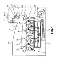
- Figure 1 is a schematic view showing an embodiment of a full-color image forming apparatus (a full-color printer) which employs a conventional electrophotographic process and includes an intermediary transfer belt (a belt member) as a transfer medium.
- Figure 2 is a schematic enlarged view of a peripheral portion of a process cartridge used in this image forming apparatus.
- the image forming apparatus includes a process cartridge 1a for forming an image of yellow, a process cartridge 1b for forming an image of magenta, a process cartridge 1c for forming an image of cyan, and a process cartridge 1d for forming an image of black.
- these process cartridges are used as image forming units.
- These four process cartridges 1a, 1b, 1c and 1d are arranged in a line at regular intervals.
- drum-type electrophotographic photosensitive members 41a, 41b, 41c and 41d, each as an image bearing member (hereinafter referred to as "photosensitive drum(s)" are provided, respectively.
- Each of the process cartridges 1a, 1b, 1c and 1d is configured to be independently detachably mountable to an apparatus main assembly with respect to a front-rear direction of the apparatus main assembly.
- a primary charger 42 as a charging member
- a developing device 43 as a developing means
- a transfer roller 2 (2a, 2b, 2c and 2d in Figure 1 ) as a transfer means
- a cleaner 45 as a cleaning means
- a toner accommodating portion 44 in which a toner is accommodated is provided and to the toner accommodating portion 44, a remaining toner amount detecting member 46 is provided.
- the photosensitive drum 41 is a negatively chargeable OPC photosensitive member and includes a drum base member of aluminum and a photoconductive layer disposed on the drum base member.
- the photosensitive drum 41 is rotationally driven at a predetermined process speed by a driving device (not shown).
- the primary charger 42 as a primary charging means electrically uniformly charges a surface of an associated photosensitive drum 41 to a predetermined negative potential by a charging bias applied from a charging bias voltage source (not shown).
- the exposure device 6 is constituted by a laser light emitting means for emitting light corresponding to a time-series electric digital pixel signal of given image information, a polygonal lens, a reflection mirror, etc.
- the laser exposure device 6 forms electrostatic latent images of respective colors corresponding to image information on the photosensitive drums 41a, 41b, 41c and 41d, respectively, electrically charged by the respective primary chargers 42 by subjecting the respective photosensitive drums 41a, 41b, 41c and 41d to light exposure.
- the developing device 43 develops each electrostatic latent image into a toner image by depositing an associated color toner on the electrostatic latent image formed on an associated photosensitive drum 41.
- a toner stirring member 44a is provided in the toner accommodating portion 44.
- the toner stirring member 44a is constituted by a sheet-like member extending in the entire area with respect to a front-rear direction on the drawing of Figure 2 .
- the toner stirring member 44a is rotated in a direction indicated by an arrow ( Figure 2 ) by an unshown driving means, so that the toner in the toner accommodating portion 44 is sent to the developing device 43.
- the remaining toner amount detecting member 46 includes an optical detecting element by which presence or absence of the toner in the toner accommodating portion 44 is detected.
- the transfer rollers 2a, 2b, 2c and 2d as the primary transfer means are disposed so that these rollers are press-contactable with the respective photosensitive drums 41a, 41b, 41c and 41d, respectively, by the medium of the intermediary transfer belt 8 as the transfer medium.
- the toner images on the respective photosensitive drums are transferred onto the intermediary transfer belt 8.
- the cleaner 45 includes a fur brush or a cleaning blade for removing a transfer residual toner, remaining on the photosensitive drum 41 after primary transfer, from the photosensitive drum 41.
- the intermediary transfer belt 8 is constituted by a dielectric resin material such as a polycarbonate film, a polyethylene terephthalate (resin) film, or a polyvinylidene fluoride (resin) film.
- a dielectric resin material such as a polycarbonate film, a polyethylene terephthalate (resin) film, or a polyvinylidene fluoride (resin) film.
- the process cartridges for the respective colors are disposed below the intermediary transfer belt 8.
- a secondary transfer opposite roller is disposed so that it is press-contactable with a secondary transfer roller by the medium of the intermediary transfer belt 8.
- the toner images superposed on the intermediary transfer belt 8 are transferred at the secondary transfer portion 3 onto a recording material P conveyed to the secondary transfer portion 3.
- a fixing device 5 including a fixing roller and a pressing roller is disposed at a portion downstream from and above the secondary transfer portion 3 with respect to a conveyance direction of the recording material P.
- a substantially vertical conveying path is formed between the secondary transfer portion 3 and the fixing device 5.
- the toner images transferred onto the recording material P at the secondary transfer portion 3 are fixed on the recording material P under application of heat and pressure by the fixing device 5.
- each of the photosensitive drums 41a, 41b, 41c and 41d, of the process cartridges 1a, 1b, 1c and 1d, rotationally driven at a predetermined process speed is negatively charged uniformly by an associated primary charger 42.
- the exposure device 6 emits laser light, corresponding to a color-separated image signal inputted from external equipment, from a laser emitting element, so that an electrostatic latent image of each color is formed on an associated photosensitive drum 41a, 41b, 41c or 41d by the laser light exposure through the polygonal lens, the reflection mirror, etc.
- a yellow toner is deposited by the developing device 43 to which a developing bias (voltage) of an identical polarity to a charge polarity (negative polarity) of the photosensitive drum 41a is applied, so that the electrostatic latent image is visualized as a yellow toner image.
- This yellow toner image is then primary-transferred onto a driven intermediary transfer belt 8 at the primary transfer portion between the photosensitive drum 41a and the transfer roller 2a by the transfer roller 2a to which a primary transfer bias (of a (positive) polarity opposite to the charge polarity of the toner) is applied.
- the intermediary transfer belt 8 onto which the yellow toner image is transferred is moved toward the process cartridge 1b. Then, also in the process cartridge 1b, similarly as in the above described manner, a magenta toner image formed on the photosensitive drum 41b is superposed and transferred onto the yellow toner image on the intermediary transfer belt 8 at an associated primary transfer portion.
- transfer residual toner remaining on each photosensitive drum 41 is scraped off the photosensitive drum 41 by the fur brush or the like provided in the drum cleaning device 45, thus being collected.
- the recording material P fed from a sheet feeding cassette 4 or a manual feeding tray through a feeding path 25 is conveyed to the secondary transfer portion 3 by registration rollers 9.
- the full-color toner images are secondary-transferred simultaneously by the secondary transfer roller to which a secondary transfer bias (of a (positive) polarity opposite to the charge polarity of the toner) is applied.
- the recording material P on which the full-color toner images are formed is conveyed to the fixing device 5, in which the full-color toner images are heated and pressed in a fixing nip between the fixing roller and the pressing roller to be heat-fixed on a surface of the recording material P. Thereafter, the recording material P is discharged on a sheet discharge tray 7 at an upper surface of the apparatus main assembly by sheet discharging rollers 11, so that a series of image forming operations is completed. Incidentally, secondary transfer residual toner or the like remaining on the intermediary transfer belt 8 is removed and collected by an unshown cleaning device.
- Figure 2 shows a structure of the process cartridge in a state in which the process cartridge is mounted in the image forming apparatus.
- a space is horizontally occupied principally by devices concerning the image forming process including the charging device 42, the cleaner (cleaning device) 45 and the developing device 43.
- a substantially arcuate concave portion (having such a shape that it extends downwardly away from an opposing surface of an adjacent process cartridge) is provided at a lower left portion of a side surface (wall) of the toner accommodating portion 44.
- the photosensitive drum is disposed in an uppermost position with respect to the vertical direction in order that the intermediary transfer belt and the photosensitive drum contact each other.
- a developing sleeve (developer carrying member) of the developing means is required to be adjacent to the photosensitive drum.
- the toner accommodating portion is located on a lower side than the photosensitive drum in the process cartridge.
- the toner accommodating portion is required to be disposed in a rotatable range of the toner stirring member in order that the toner in the lower toner accommodating portion is conveyed to the upper developing sleeve.
- the shape of the toner accommodating portion disposed on the lower side of the process cartridge is inevitably a substantially arcuate shape with a point, substantially identical to a rotation shaft of the toner stirring member 44a, as a center.
- a space between adjacent process cartridges is small on the photosensitive drum side (the upper side of Figure 2 ) and large on the toner accommodating portion side (the lower side of Figure 2 ). That is, on the lower side than the photosensitive drums of the first process cartridge (first image forming unit) and the second process cartridge (second image forming unit), it is possible to form the (large) space without increasing the distance between the photosensitive drums.
- the remaining toner amount detecting member 46 is provided.
- This detecting member 46 is provided in the above-described space so that it is projected from the toner accommodating portion of the process cartridge at a substantially central portion with respect to a longitudinal direction of the process cartridge.
- Figure 3 is a schematic perspective view of an outer shape of the parallel-arranged process cartridges 1a, 1b, 1c and 1d as seen from below the process cartridges.
- a projected portion (A in Figure 3 ) provided at the lower left portion ( Figure 2 ) of the process cartridge 1 the above-described remaining toner amount detecting member 46 ( Figure 2 ) is provided. It is necessary to efficiently perform stirring by the toner stirring member 44a and to increase a toner accommodating volume of the toner accommodating portion with maximum efficiency. For that reason, the inner wall shape of the toner accommodating portion 44 is, as described above, required to be configured so that the substantially arcuate shape extends over the entire longitudinal area with the rotation shaft of the toner stirring member 44a as the center.
- the projected portion A by the remaining toner amount detecting member 46 is provided.
- the process cartridges 1 are required to be independently inserted and extracted for each color, so that the outer shape of the adjacent process cartridge cannot interfere with that of an associated process cartridge with respect to an insertion/extraction direction (indicated by double-pointed arrows in Figure 3 ).
- a space is inevitably created.
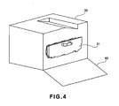
- Figures 4 , 5 and 6 are schematic entire apparatus perspective views for illustrating the exchanging operation of the process cartridge with respect to the apparatus main assembly.
- Figure 4 shows such a state that a main assembly door (front cover) 60 of an image forming apparatus 30 in which the process cartridges 1a, 1b, 1c and 1d are mounted is opened.
- An inserting opening 53 ( Figure 5 ), provided at a side surface of the apparatus main assembly, for the process cartridges 1a, 1b, 1c and 1d is covered with an openable cover 51 as an openable member.
- the openable cover 51 is provided at a side surface portion of the main assembly of the image forming apparatus.
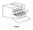
- Figure 5 shows a state in which the openable cover 51 is opened and the process cartridges 1a, 1b, 1c and 1d can be dismounted through the inserting opening 53.
- a single opening for mounting and demounting the plurality of process cartridges provided to the image forming apparatus is provided in order to decrease a distance between adjacent contact portions each between an associated photosensitive drum and the intermediary transfer belt.
- Figure 6 shows a state in which the process cartridge 1c is demounted from the apparatus main assembly placed in the state of Figure 5 .
- the process cartridges 1a, 1b, 1c and 1d are vertically moved in interrelation with an opening/closing operation of the openable cover 51. That is, after the process cartridges are mounted in the image forming apparatus, in interrelation with a closing operation of a lever or the openable cover 51, the process cartridges are upwardly moved from the mounting position toward an image formable position. Specifically, rails on the apparatus main assembly side for supporting lower portions of the process cartridges 1a, 1b, 1c and 1d are moved up and down in interrelation with the openable cover 51.
- the process cartridges 1a, 1b, 1c and 1d are moved up and when the openable cover 51 is opened, the process cartridges 1a, 1b, 1c and 1d are moved down.
- the photosensitive drums are required to contact the intermediary transfer belt during image formation and therefore there is a possibility of damage of the intermediary transfer belt when the mounting and demounting operations of the process cartridges are performed at a position identical to that during the image formation.
- the process cartridges are vertically moved but the intermediary transfer belt may also be configured to be vertically moved.
- process cartridges 1a, 1b, 1c and 1d When the process cartridges 1a, 1b, 1c and 1d are moved up, these process cartridges strike against abutting portions 54a, 54b, 54c and 54d on the apparatus main assembly side ( Figure 5 ), so that the process cartridges 1a, 1b, 1c and 1d are portioned and fixed in the apparatus main assembly. On the other hand, when the process cartridges 1a, 1b, 1c and 1d are moved down, the process cartridges 1a, 1b, 1c and 1d are separated from the abutting portions 54a, 54b, 54c and 54d. Thus, the process cartridges are placed in such a state that the process cartridges are only mounted on the rails on the apparatus main assembly side, so that the process cartridges are demountable to enable the exchanging operation.
- the single opening for mounting and demounting the plurality of process cartridges is employed, so that when the process cartridges are mounted, the number of guide portions which can be provided in the image forming apparatus is decreased.
- a user inserts the process cartridges into the image forming apparatus main assembly with an improper (erroneous) attitude when the user mounts the process cartridges in the apparatus main assembly. For this reason, from the viewpoint of usability, it is necessary to newly provide guide portions.
- these new guide portions are provided at an inner surface of the openable cover.
- the inner surface of the openable cover 51 (an upper surface in an opened state of the openable cover 51) functions as a guiding surface at the time of inserting the process cartridges 1a, 1b, 1c and 1d.
- guiding ribs 52a, 52b, 52c and 52d which are projected guide portions are provided.
- These guiding ribs 52a, 52b, 52c and 52d are formed so as to guide side surfaces of the respective process cartridges 1a, 1b, 1c and 1d in the insertion direction and are each configured to have a higher portion (B in Figure 7 ) closest to the inserting opening 53.
- the higher portions of the guide portions are located on the rotational center shaft side of the openable cover.
- the portion B closest to the inserting opening 53 is high, so that the process cartridge 1 can easily be guided to a predetermined portion and a predetermined attitude immediately before start of insertion of the process cartridge 1.
- the inserting opening 53 for the process cartridges inevitably constitutes a single large hole (opening). In the image forming apparatus having such a large inserting opening, a greater effected of rectifying the portion and attitude of the process cartridges by the higher B portions closest to the inserting opening is achieved.
- Each of the guiding ribs 52a, 52b, 52c 52d is provided so that at least one of adjacent two process cartridges is guided during mounting.
- Figures 7 , 8 and 9 are schematic enlarged perspective views each showing a neighborhood of the process cartridge inserting opening.
- Each of the spaces C is the above-described space created by the substantially arcuate portion located at the lower left portion of the process cartridge 1 ( Figures 2 and 3 ) and is a space created by upward movement of the process cartridge 1.
- the higher portions B of the guiding ribs are accommodated in the spaces C between adjacent process cartridges, so that a portion of the openable cover 51 during the closing of the openable cover 51 can be brought at close as possible to the process cartridges 1.
- the guide portions of the openable member are configured to have partially higher portions close to the mounting portions of the image forming units but there is no problem even when the guide portions have no lower portions. Further, the entire guide portions are not required to be higher with respect to the image forming unit mounting direction but there is no problem even when a part of each guide portion is lower with respect to the image forming unit mounting direction.
- the guide portions of the openable member guide the side surfaces of the image forming units but there is no problem even when additional guide portions for guiding bottom (lower) surfaces of the image forming units are provided in addition to the guide portions.
- the present invention even when the guide portions provided to the openable member are partially increased in height, it is possible to accommodate the guide portions in the spaces among the image forming units without increasing the distance between adjacent contact portions each between the image bearing member and the belt member.
- the description is made by taking the intermediary transfer belt as an example of the transfer medium but the present invention is not limited thereto.
- the present invention is also applicable to even a constitution in which toner images formed on the respective photosensitive drums are directly transferred successively onto the recording material as the transfer medium without using the intermediary transfer belt.
Landscapes
- Physics & Mathematics (AREA)
- General Physics & Mathematics (AREA)
- Engineering & Computer Science (AREA)
- Computer Vision & Pattern Recognition (AREA)
- Electrophotography Configuration And Component (AREA)
- Dry Development In Electrophotography (AREA)
- Color Electrophotography (AREA)
Applications Claiming Priority (1)
| Application Number | Priority Date | Filing Date | Title |
|---|---|---|---|
| JP2007158601A JP5159176B2 (ja) | 2007-06-15 | 2007-06-15 | 画像形成装置 |
Publications (3)
| Publication Number | Publication Date |
|---|---|
| EP2003519A2 EP2003519A2 (en) | 2008-12-17 |
| EP2003519A3 EP2003519A3 (en) | 2011-07-06 |
| EP2003519B1 true EP2003519B1 (en) | 2015-09-16 |
Family
ID=39740047
Family Applications (1)
| Application Number | Title | Priority Date | Filing Date |
|---|---|---|---|
| EP08158198.5A Not-in-force EP2003519B1 (en) | 2007-06-15 | 2008-06-13 | Image forming apparatus with cartridge mounting means |
Country Status (5)
| Country | Link |
|---|---|
| US (1) | US7796916B2 (enExample) |
| EP (1) | EP2003519B1 (enExample) |
| JP (1) | JP5159176B2 (enExample) |
| KR (1) | KR100990568B1 (enExample) |
| CN (1) | CN101324780B (enExample) |
Families Citing this family (13)
| Publication number | Priority date | Publication date | Assignee | Title |
|---|---|---|---|---|
| JP5137647B2 (ja) * | 2007-05-15 | 2013-02-06 | キヤノン株式会社 | 画像形成装置 |
| JP5159225B2 (ja) * | 2007-09-21 | 2013-03-06 | キヤノン株式会社 | 画像形成装置 |
| JP5523009B2 (ja) * | 2009-08-07 | 2014-06-18 | キヤノン株式会社 | 画像形成装置 |
| JP5286241B2 (ja) * | 2009-12-17 | 2013-09-11 | 京セラドキュメントソリューションズ株式会社 | 画像形成装置 |
| JP5381746B2 (ja) * | 2010-01-26 | 2014-01-08 | 株式会社リコー | 定着装置及び画像形成装置 |
| KR101236911B1 (ko) * | 2010-08-23 | 2013-02-25 | 삼성전자주식회사 | 현상기 및 이를 채용한 화상형성장치 |
| JP5307200B2 (ja) | 2011-07-28 | 2013-10-02 | シャープ株式会社 | トナーカートリッジ支持装置とこれを用いる画像形成装置及びトナーカートリッジ支持方法 |
| CN104508571B (zh) * | 2012-07-24 | 2020-04-24 | 夏普株式会社 | 图像形成装置 |
| JP5459734B2 (ja) * | 2012-07-24 | 2014-04-02 | シャープ株式会社 | 画像形成装置 |
| JP6061599B2 (ja) * | 2012-10-01 | 2017-01-18 | キヤノン株式会社 | 画像形成装置 |
| US10496034B2 (en) * | 2016-11-01 | 2019-12-03 | Canon Kabushiki Kaisha | Image forming apparatus |
| JP7159775B2 (ja) * | 2018-10-15 | 2022-10-25 | コニカミノルタ株式会社 | 画像形成装置 |
| JP7237699B2 (ja) * | 2019-03-29 | 2023-03-13 | キヤノン株式会社 | 画像形成装置 |
Family Cites Families (19)
| Publication number | Priority date | Publication date | Assignee | Title |
|---|---|---|---|---|
| JP3854708B2 (ja) * | 1997-02-28 | 2006-12-06 | キヤノン株式会社 | カラー画像形成装置 |
| JP2001066968A (ja) * | 1999-08-31 | 2001-03-16 | Canon Inc | 画像形成装置 |
| JP2001242762A (ja) | 2000-03-01 | 2001-09-07 | Kyocera Mita Corp | 画像形成装置 |
| JP4772178B2 (ja) * | 2000-05-19 | 2011-09-14 | デュプロ精工株式会社 | 画像形成装置 |
| JP2002062782A (ja) | 2000-06-09 | 2002-02-28 | Fuji Xerox Co Ltd | 画像形成装置のサブユニット取付構造及びサブユニット取付、取外し方法 |
| EP1288739A3 (en) | 2001-08-24 | 2006-04-05 | Canon Kabushiki Kaisha | Recycling method and image forming apparatus manufactured using recycling method |
| EP1331525A3 (en) * | 2002-01-25 | 2004-06-23 | Ricoh Company, Ltd. | Image forming apparatus with improved image quality and maintenance workability |
| JP2003345133A (ja) * | 2002-05-24 | 2003-12-03 | Ricoh Co Ltd | 画像形成装置 |
| JP4107573B2 (ja) | 2002-09-10 | 2008-06-25 | 株式会社リコー | 画像形成装置 |
| JP4107574B2 (ja) * | 2002-10-03 | 2008-06-25 | 株式会社リコー | 画像形成装置、プロセスカートリッジ、及び、カバー部材 |
| JP4025663B2 (ja) * | 2003-03-04 | 2007-12-26 | 松下電器産業株式会社 | 像担持体着脱機構及びこれを備えたカラー画像形成装置 |
| JP4717455B2 (ja) | 2004-02-27 | 2011-07-06 | キヤノン株式会社 | 画像形成装置 |
| US7139507B2 (en) | 2004-03-22 | 2006-11-21 | Fuji Xerox Co. Ltd. | Image forming apparatus and method of mounting and demounting process cartridge |
| JP2005266670A (ja) | 2004-03-22 | 2005-09-29 | Fuji Xerox Co Ltd | 画像形成装置及びプロセスカートリッジの着脱方法 |
| JP2005316192A (ja) | 2004-04-28 | 2005-11-10 | Canon Inc | 電子写真画像形成装置 |
| JP4616591B2 (ja) * | 2004-07-20 | 2011-01-19 | 株式会社リコー | 画像形成装置 |
| JP4265534B2 (ja) * | 2004-12-27 | 2009-05-20 | ブラザー工業株式会社 | 画像形成装置 |
| JP4432813B2 (ja) | 2005-03-24 | 2010-03-17 | ブラザー工業株式会社 | 画像形成装置 |
| JP2007003660A (ja) * | 2005-06-22 | 2007-01-11 | Murata Mach Ltd | 画像形成装置 |
-
2007
- 2007-06-15 JP JP2007158601A patent/JP5159176B2/ja not_active Expired - Fee Related
-
2008
- 2008-06-11 US US12/137,281 patent/US7796916B2/en active Active
- 2008-06-13 EP EP08158198.5A patent/EP2003519B1/en not_active Not-in-force
- 2008-06-13 KR KR1020080055658A patent/KR100990568B1/ko not_active Expired - Fee Related
- 2008-06-13 CN CN200810125584XA patent/CN101324780B/zh active Active
Also Published As
| Publication number | Publication date |
|---|---|
| EP2003519A3 (en) | 2011-07-06 |
| EP2003519A2 (en) | 2008-12-17 |
| CN101324780B (zh) | 2010-08-11 |
| JP5159176B2 (ja) | 2013-03-06 |
| KR100990568B1 (ko) | 2010-10-29 |
| JP2008310120A (ja) | 2008-12-25 |
| CN101324780A (zh) | 2008-12-17 |
| US7796916B2 (en) | 2010-09-14 |
| US20080310882A1 (en) | 2008-12-18 |
| KR20080110528A (ko) | 2008-12-18 |
Similar Documents
| Publication | Publication Date | Title |
|---|---|---|
| EP2003519B1 (en) | Image forming apparatus with cartridge mounting means | |
| EP3992726B1 (en) | Image forming apparatus | |
| US7983597B2 (en) | Color electrophotographic image forming apparatus with gripping portions for cartridges | |
| US7817936B2 (en) | Color electrophotographic image forming apparatus | |
| US8437660B2 (en) | Image forming apparatus with movable member for supporting cartridges | |
| US20110103835A1 (en) | Developing cartridge | |
| JP2005275374A (ja) | 画像形成装置 | |
| EP2397918B1 (en) | Colour electrophotographic image forming apparatus | |
| US7912405B2 (en) | Image forming apparatus having a plurality of image forming units | |
| US20120219323A1 (en) | Image forming apparatus | |
| CN114077181B (zh) | 成像设备 | |
| US12393134B2 (en) | Movable member and image forming apparatus | |
| US10670995B2 (en) | Image forming apparatus | |
| US20060078350A1 (en) | Color image forming apparatus |
Legal Events
| Date | Code | Title | Description |
|---|---|---|---|
| PUAI | Public reference made under article 153(3) epc to a published international application that has entered the european phase |
Free format text: ORIGINAL CODE: 0009012 |
|
| AK | Designated contracting states |
Kind code of ref document: A2 Designated state(s): AT BE BG CH CY CZ DE DK EE ES FI FR GB GR HR HU IE IS IT LI LT LU LV MC MT NL NO PL PT RO SE SI SK TR |
|
| AX | Request for extension of the european patent |
Extension state: AL BA MK RS |
|
| PUAL | Search report despatched |
Free format text: ORIGINAL CODE: 0009013 |
|
| AK | Designated contracting states |
Kind code of ref document: A3 Designated state(s): AT BE BG CH CY CZ DE DK EE ES FI FR GB GR HR HU IE IS IT LI LT LU LV MC MT NL NO PL PT RO SE SI SK TR |
|
| AX | Request for extension of the european patent |
Extension state: AL BA MK RS |
|
| 17P | Request for examination filed |
Effective date: 20120109 |
|
| AKX | Designation fees paid |
Designated state(s): DE FR GB IT |
|
| REG | Reference to a national code |
Ref country code: DE Ref legal event code: R079 Ref document number: 602008040171 Country of ref document: DE Free format text: PREVIOUS MAIN CLASS: G03G0021180000 Ipc: G03G0015010000 |
|
| GRAP | Despatch of communication of intention to grant a patent |
Free format text: ORIGINAL CODE: EPIDOSNIGR1 |
|
| RIC1 | Information provided on ipc code assigned before grant |
Ipc: G03G 21/16 20060101ALI20140701BHEP Ipc: G03G 15/01 20060101AFI20140701BHEP Ipc: G03G 21/18 20060101ALI20140701BHEP |
|
| INTG | Intention to grant announced |
Effective date: 20140722 |
|
| RIN1 | Information on inventor provided before grant (corrected) |
Inventor name: KATO, TAKAYUKI Inventor name: KOTSUKA, HIDEKI |
|
| GRAP | Despatch of communication of intention to grant a patent |
Free format text: ORIGINAL CODE: EPIDOSNIGR1 |
|
| INTG | Intention to grant announced |
Effective date: 20150331 |
|
| GRAS | Grant fee paid |
Free format text: ORIGINAL CODE: EPIDOSNIGR3 |
|
| GRAA | (expected) grant |
Free format text: ORIGINAL CODE: 0009210 |
|
| AK | Designated contracting states |
Kind code of ref document: B1 Designated state(s): DE FR GB IT |
|
| REG | Reference to a national code |
Ref country code: GB Ref legal event code: FG4D |
|
| REG | Reference to a national code |
Ref country code: DE Ref legal event code: R096 Ref document number: 602008040171 Country of ref document: DE |
|
| PG25 | Lapsed in a contracting state [announced via postgrant information from national office to epo] |
Ref country code: IT Free format text: LAPSE BECAUSE OF FAILURE TO SUBMIT A TRANSLATION OF THE DESCRIPTION OR TO PAY THE FEE WITHIN THE PRESCRIBED TIME-LIMIT Effective date: 20150916 |
|
| REG | Reference to a national code |
Ref country code: DE Ref legal event code: R097 Ref document number: 602008040171 Country of ref document: DE |
|
| PLBE | No opposition filed within time limit |
Free format text: ORIGINAL CODE: 0009261 |
|
| STAA | Information on the status of an ep patent application or granted ep patent |
Free format text: STATUS: NO OPPOSITION FILED WITHIN TIME LIMIT |
|
| 26N | No opposition filed |
Effective date: 20160617 |
|
| REG | Reference to a national code |
Ref country code: FR Ref legal event code: ST Effective date: 20170228 |
|
| PG25 | Lapsed in a contracting state [announced via postgrant information from national office to epo] |
Ref country code: FR Free format text: LAPSE BECAUSE OF NON-PAYMENT OF DUE FEES Effective date: 20160630 |
|
| PGFP | Annual fee paid to national office [announced via postgrant information from national office to epo] |
Ref country code: DE Payment date: 20230523 Year of fee payment: 16 |
|
| PGFP | Annual fee paid to national office [announced via postgrant information from national office to epo] |
Ref country code: GB Payment date: 20230523 Year of fee payment: 16 |
|
| REG | Reference to a national code |
Ref country code: DE Ref legal event code: R119 Ref document number: 602008040171 Country of ref document: DE |
|
| GBPC | Gb: european patent ceased through non-payment of renewal fee |
Effective date: 20240613 |
|
| PG25 | Lapsed in a contracting state [announced via postgrant information from national office to epo] |
Ref country code: DE Free format text: LAPSE BECAUSE OF NON-PAYMENT OF DUE FEES Effective date: 20250101 |
|
| PG25 | Lapsed in a contracting state [announced via postgrant information from national office to epo] |
Ref country code: GB Free format text: LAPSE BECAUSE OF NON-PAYMENT OF DUE FEES Effective date: 20240613 |