EP2002166B1 - Verbindungsanordnung - Google Patents
Verbindungsanordnung Download PDFInfo
- Publication number
- EP2002166B1 EP2002166B1 EP07711848A EP07711848A EP2002166B1 EP 2002166 B1 EP2002166 B1 EP 2002166B1 EP 07711848 A EP07711848 A EP 07711848A EP 07711848 A EP07711848 A EP 07711848A EP 2002166 B1 EP2002166 B1 EP 2002166B1
- Authority
- EP
- European Patent Office
- Prior art keywords
- ring
- supporting
- cutting
- accordance
- connecting assembly
- Prior art date
- Legal status (The legal status is an assumption and is not a legal conclusion. Google has not performed a legal analysis and makes no representation as to the accuracy of the status listed.)
- Active
Links
- 230000002093 peripheral effect Effects 0.000 claims 2
- 238000007789 sealing Methods 0.000 description 5
- 238000011179 visual inspection Methods 0.000 description 4
- 244000089486 Phragmites australis subsp australis Species 0.000 description 3
- 230000009172 bursting Effects 0.000 description 3
- 241001295925 Gegenes Species 0.000 description 2
- 230000004308 accommodation Effects 0.000 description 1
- 238000007598 dipping method Methods 0.000 description 1
- 238000005553 drilling Methods 0.000 description 1
- 238000004073 vulcanization Methods 0.000 description 1
Images

Classifications
-
- F—MECHANICAL ENGINEERING; LIGHTING; HEATING; WEAPONS; BLASTING
- F16—ENGINEERING ELEMENTS AND UNITS; GENERAL MEASURES FOR PRODUCING AND MAINTAINING EFFECTIVE FUNCTIONING OF MACHINES OR INSTALLATIONS; THERMAL INSULATION IN GENERAL
- F16L—PIPES; JOINTS OR FITTINGS FOR PIPES; SUPPORTS FOR PIPES, CABLES OR PROTECTIVE TUBING; MEANS FOR THERMAL INSULATION IN GENERAL
- F16L19/00—Joints in which sealing surfaces are pressed together by means of a member, e.g. a swivel nut, screwed on or into one of the joint parts
- F16L19/06—Joints in which sealing surfaces are pressed together by means of a member, e.g. a swivel nut, screwed on or into one of the joint parts in which radial clamping is obtained by wedging action on non-deformed pipe ends
- F16L19/061—Joints in which sealing surfaces are pressed together by means of a member, e.g. a swivel nut, screwed on or into one of the joint parts in which radial clamping is obtained by wedging action on non-deformed pipe ends a pressure ring being arranged between the clamping ring and the threaded member or the connecting member
-
- F—MECHANICAL ENGINEERING; LIGHTING; HEATING; WEAPONS; BLASTING
- F16—ENGINEERING ELEMENTS AND UNITS; GENERAL MEASURES FOR PRODUCING AND MAINTAINING EFFECTIVE FUNCTIONING OF MACHINES OR INSTALLATIONS; THERMAL INSULATION IN GENERAL
- F16L—PIPES; JOINTS OR FITTINGS FOR PIPES; SUPPORTS FOR PIPES, CABLES OR PROTECTIVE TUBING; MEANS FOR THERMAL INSULATION IN GENERAL
- F16L19/00—Joints in which sealing surfaces are pressed together by means of a member, e.g. a swivel nut, screwed on or into one of the joint parts
- F16L19/08—Joints in which sealing surfaces are pressed together by means of a member, e.g. a swivel nut, screwed on or into one of the joint parts with metal rings which bite into the wall of the pipe
- F16L19/083—Joints in which sealing surfaces are pressed together by means of a member, e.g. a swivel nut, screwed on or into one of the joint parts with metal rings which bite into the wall of the pipe the longitudinal cross-section of the ring not being modified during clamping
Definitions
- the invention relates to a connection arrangement for connecting a pipe or pipe socket with a connecting body having a conical bore tapering from an end face, the connecting arrangement having a longitudinal axis, a supporting ring extending from a first holding surface in the same direction as the conical bore of the connecting body has flared tapered bore and which is supported with a second retaining surface against the end face of the connecting body, a union nut which is screwed onto a thread of the connecting body and which forms a clamping surface, and a cutting ring which sits in the tapered bore of the support ring and a pressing surface for applying force has by the clamping surface of the union nut.
- connection arrangement is known from DE 196 37 129 C2 known.
- the clamping surface of the union nut is conical.
- the support ring has one of the clamping surface of the union nut facing surface, which is formed with a matching clamping surface cone angle. The cutting ring immersed in the assembled state so far into the tapered bore of the support ring, that both the support ring and the cutting ring abut the clamping surface of the nut.
- DE 40 38 539 C1 shows a connection arrangement in which the cutting ring is supported via a radial to the tube axis extending surface against a likewise radially to the tube axis extending stop surface of a sealing ring. in this connection the cutting ring and the sealing ring between the union nut and the connecting body are clamped axially one behind the other.
- the EP 1 484 542 A1 shows a connection arrangement in which a support ring is acted upon indirectly via a cutting ring by a union nut.
- the support ring has a bore with a cylindrical and a conical portion, which immediately surrounds the tube.
- On the side facing away from the conical portion of the support ring acts on another cutting ring with a cutting edge.
- In the conical portion of the support ring of the cutting ring is inserted with a cutting edge forming portion.
- the DE 197 27 149 A1 shows a connection arrangement with a support ring, a cutting ring and a union nut, wherein the union nut acts directly on the support ring and the cutting ring.
- the support ring has a cylindrical portion and a conical portion, wherein the cutting ring is inserted from the side of the cylindrical portion in the support ring and forms two cutting edges in the region of the conical portion.
- On the side facing away from the union nut close the cutting ring and the support ring axially flush.
- the US 3,736,008 shows a connection arrangement with a support ring, a cutting ring and a union nut, wherein the union nut acts on the support ring indirectly via the cutting ring.
- the support ring has a cylindrical portion with which it immediately surrounds the tube and at the end of two cutting edges are formed. By cutting into the tube, the front cutting edge raises a tape throw.
- the support ring has a conical portion which opens into a second cylindrical portion of larger diameter. In this cylindrical / conical portion of the support ring, the cutting ring engages with a portion on which also two cutting edges are formed.
- a connection arrangement which has a union nut and cutting ring, but waived a support ring, shows the DE 43 11 280 A1 ,
- the cutting ring is axially acted upon by screwing the union nut on the connecting body with force and forms a collar Aufsch in the outer surface of the tube.
- the cutting ring is axially supported in the assembled state of the connection assembly.
- the tube is supported axially against the cutting ring and this against the union nut, so that the tube can not be pulled out of the connecting body.
- connection arrangement is initially mounted according to regulations. Thereafter, the union nut is unscrewed from the connector body and the tube end removed from the connector body. The cut deeper of the cutting ring then undergoes a visual inspection by the installer who judges whether the cutting ring has cut deeply enough into the pipe before the joint assembly is reassembled. In visual inspection, however, it is possible that the support ring from the pipe end and thus from the pipe slips, making re-assembly is more expensive.
- the object of the present invention is to provide a connection arrangement in which the assembly is made simpler.
- the geometry of the cutting ring is designed such that at a sufficient depth of cut of the cutting ring of the collar throw has an outer diameter which is greater than the smallest inner diameter of the support ring. This ensures that the support ring after proper assembly and disassembly of the connection assembly in the visual inspection of the cutting depth of the cutting ring can not slip from the pipe.
- the geometry of the cutting ring should be designed such that at an insufficient depth of cut of the cutting ring Bundiller scheme has an outer diameter which is smaller than the smallest inner diameter of the support ring, so that the support ring can be moved across the Bundiller scheme away to the pipe end and from Pipe can be removed.
- Whether the cutting ring has cut sufficiently deep into the pipe or not can then be determined simply by whether or not after assembly and disassembly of the connection arrangement of the support ring is held on the pipe. If he does not move over the collar throw, the depth of cut is sufficient. If he pushes himself over the collar throw, the depth of cut is not sufficient.
- the connection arrangement of the support ring is held with its first holding surface in contact with the Bundaufsch.
- This can be done be achieved, that the cutting ring terminates axially flush with the first holding surface of the support ring.
- the cutting ring can also protrude axially in the direction of the tube end from the conical bore of the support ring and thus from the first holding surface of the support ring in the direction of the tube end.
- the union nut preferably has a conical bore which forms a clamping surface tapering in the opposite direction to the conical bore of the connecting body in the form of a conical surface.
- the depth of cut depends on the cone angle of the tapered bore of the support ring and on the mounting length, where the mounting length is the length over which the cutting ring cuts into the pipe.
- the mounting path can therefore be provided that in the assembled state of the connection assembly of the cutting ring is axially supported with a first stop surface against a second stop surface of the support ring.
- the cutting ring has a first support surface, by means of which the cutting ring is supported in the radial direction on the longitudinal axis against a second support surface of the support ring.
- the first support surface may be the first stop surface and the second support surface may be the second stop surface.
- the support ring is made of a high quality when over-mounted and especially for pipes Material strongly stressed radially outward and can burst.
- the clamping surface is designed in the form of a conical bore with an opening angle of 90 °.
- Standardized connecting bodies have a conical bore with an opening angle of 24 °.
- the opening angle of the tapered bore of the support ring is adapted to that of the connecting body and is therefore also 24 °.
- the opening angle is preferably 13.2 ° to 24.6 °.
- the cutting ring preferably has a support portion and a cutting edge portion, wherein the support portion forms the first support surface and the cutting edge portion is received in the tapered bore of the support ring.
- the support surfaces can be conical.
- the first support surface is formed by a circumferential undercut of the cutting ring and the second support surface by a circumferential projection of the support ring.
- the circumferential projection is added in the undercut.
- the support ring can protrude over a part of the length of the conical bore of the connecting body in this, so that the first holding surface is arranged in the conical bore of the connecting body.
- the support ring which is strongly stressed radially outwards, experiences a support radially outward.
- the cutting edge section then extends into the conical bore of the connecting body. This ensures that the cutting edge section is supported radially against the connecting body via the projecting into the conical bore of the connecting body support ring.
- a cutting edge of the cutting ring can be arranged within the conical bore of the connecting body, which is thus radially supported.
- the cutting ring has two cutting edges.
- one of the cutting edges can be arranged inside the conical bore of the connecting body and the other cutting edge outside the conical bore of the connecting body.
- the support ring and the tube can be formed a receiving space in which a sealing ring is received.
- the union nut may be axially supported indirectly via the cutting ring against the support ring in the assembled state of the connection arrangement.
- the union nut is axially supported with its clamping surface against the pressing surface of the cutting ring and that the cutting ring is axially supported with a first support surface against a second support surface of the support ring.
- the clamping surface of the union nut is axially supported both directly against the second support surface of the support ring and against the pressing surface of the cutting ring.
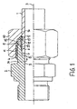
- FIGS. 1 to 3 show a connection arrangement according to the invention, in which a tube 1 is connected to a connecting body 2.
- the FIGS. 1 to 3 will be described together below.
- the connecting arrangement has a longitudinal axis 3, to which the tube 1 and the connecting body 2 are arranged centered.
- the connecting body 2 is provided on its outer surface with a thread 4 that extends from an end face 5. From the end face 5 also assumes a centered on the longitudinal axis 3 conical bore 6, which has a standard opening angle of 24 °.
- This is followed by a first cylindrical bore 7, whose diameter is matched to that of the tube 1.
- the first cylindrical bore 7 terminates in an annular surface 8, from which a diameter-reduced second cylindrical bore 9 continues.
- the tube 1 has a pipe end 36, with which it is inserted into the bore 7.
- the annular surface 8 serves to support the tube 1 against the connecting body 2 in the axial direction.
- a union nut 10 is screwed, which has a bore with a thread 11 which fits the thread 4 of the connecting body 2. Subsequent to the thread 11, a conical bore 12 is provided at the end facing away from the connecting body 2 end of the union nut 10 whose opening angle is standardized and 90 ° and which forms an opposite to the conical bore 6 of the connecting body 2 tapered clamping surface 13 in the form of a conical surface.
- the conical bore 12 of the union nut 10 terminates in a reduced diameter cylindrical bore 14, which is tuned to the outer diameter of the tube 1. The union nut 10 is pushed over the tube 1.
- a support ring 15 is present, the outer surface 16 has a diameter which is sized so large that the union nut 10 can pass it with its thread 11.
- the support ring 15 has a second holding surface 17, which rests flat in the mounted state on the end face 5 of the connecting body 2.
- the support ring 15 also has a conical bore 18, which tapers opposite to the conical bore 12 of the union nut 10.
- the opening angle of the conical bore 18 of the support ring 15 is preferably 13.2 ° to 24.6 ° and can therefore the standardized cone angle of 24 ° of the connecting body 2 correspond.
- the tube 1, the conical bore 6 of the connecting body 2 and a first holding surface 37 of the support ring 15 together form a receiving space 32 for receiving a sealing ring 33.
- the sealing ring 33 may be formed as a separate ring or with the support ring 15, for. be firmly connected by vulcanization.
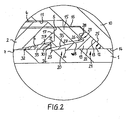
- a cutting ring 19 is provided.
- the cutting ring 19 has a cutting edge portion 20 and a support portion 21.
- the cutting edge portion 20 is conical and received in the tapered bore 18 of the support ring 15.
- the cutting ring 19 has a bore 22 with which it is pushed onto the tube 1.
- the bore 22 is designed in the region of the cutting edge section 20 such that a front cutting edge 23 and a rear cutting edge 24 are formed.
- the support portion 21 is arranged to the union nut 10.
- the support portion 21 forms a cone-shaped pressing surface 25 which is adapted to the conical bore 12 of the union nut 10 and is in abutment with this.
- the cutting ring 19 is acted upon by screwing the union nut 10 on the connecting body 2 axially with force and forms a Bundauf tone 34 in the outer surface of the tube 1. against this, the cutting ring 19 is axially supported in the assembled state of the connection assembly. As a result, the tube 1 is axially supported against the cutting ring 19 and this against the nut 10, so that the tube 1 can not be pulled out of the connector body 2.
- the geometry of the cutting ring 19, that is, the thickness of the cutting edge portion 20, the opening angle of the conical surface 35 of the cutting ring 19 in the region of the cutting edge portion 20 and the inner diameter of the cutting ring 19 in the unassembled and undeformed state relative to the outer diameter of the tube 1, is such designed that with a sufficient depth of cut of the cutting ring 19 of the collar Auf scheme 34 has an outer diameter which is greater than the smallest inner diameter of the support ring 15.
- the Bundaufsch 34th is in this case arranged between the pipe end 36 and the first holding surface 37. The support ring 15 is held with its first holding surface 37 in abutment with the Bundaufschsch 34.
- the cutting ring 19 terminates at least axially flush with the first holding surface 37 of the support ring. It is therefore also possible that the cutting edge portion 20 protrudes with the first holding surface 37 from the tapered bore 18 of the support ring 15 in the direction of the tube end 36. This ensures that the support ring 15 after proper assembly and disassembly of the connection assembly in a visual inspection of the depth of cut of the cutting ring 19 can not slip from the tube 1.
- the geometry of the cutting ring 19 should be designed such that at an insufficient depth of cut of the cutting ring 19, the collar Auf scheme 34 has an outer diameter which is smaller than the smallest inner diameter of the support ring 15 so that the support ring 15 across the Bundaufmine away to the pipe end 36 can be moved towards and can be removed from the tube 1.
- the support portion 21 further forms a first support surface 26, which faces the support ring 15 and is represented by a circumferential undercut 27.
- the first support surface 26 opens in the shape of a cone in the direction of the support ring 15.
- the support ring 15 forms a second support surface 28, which is also cone-shaped and has the same opening angle as the first support surface 26.
- the second support surface 28 is formed by a circumferential projection 29 of the support ring 15, which received in the undercut 27 of the cutting ring 19 is.
- the first support surface 26 is supported against the second support surface 28. Due to the conical configuration of the support surfaces 26, 28 of the cutting ring 19 is supported radially against deformation in the direction of the longitudinal axis 3 against deformation.
- the first support surface 26 also provides a first stop surface and the second support surface 28 is a second stop surface, wherein the cutting ring 19 to limit the assembly path, ie the path over which the cutting ring 19 cuts into the tube 1, with the first stop surface 26 axially against the second stop surface 28 of the support ring 15 is supported.
- the support ring 15 also has a holding portion 30, with which the support ring 15 is immersed in the conical bore 6 of the connecting body 2 and extends over part of the length of the conical bore 6.
- the holding portion 30 has an outer surface 31, which is also cone-shaped and is adapted to the conical bore 6 of the connecting body 2.
- the cutting edge portion 20 of the cutting ring 19 dips into the conical bore 18 of the support ring 15 so deep that it extends into the conical bore 6 of the connecting body 2.
- the front cutting edge 23 is formed on the end of the cutting edge portion 20 dipping into the tapered hole 6 of the connecting body 2, so that it is supported radially against the connecting body 2 via the holding portion 30.
- the rear cutting edge 24 is disposed within the support ring 15 and outside the cone bore 6 of the connecting body 2.
- the holding portion 30 also serves to clamp the support ring 15 on the outer surface 31 of the holding portion 30 in the conical bore 6 of the connecting body 2, so that the frictional force between the connecting body 2 and the support ring 15 is greater than between the cutting ring 19 and the union nut 10th Further, the frictional force between the support ring 15 and the cutting ring 19 is greater than between the cutting ring 19 and the union nut 10, so that when tightening the nut 10, this rotates relative to the cutting ring 19 and not the cutting ring 19 relative to the support ring 15 or the support ring 15 relative to the connecting body 2. Thus, it is effectively avoided that when tightening the nut 10, the tube 1 rotates together with the nut 10.
- the radial support of the cutting ring 19 relative to the support ring 15 prevents radial deformation of the cutting ring 19 and thus a constriction of the tube 1. This results in higher bursting pressures of the connection arrangement, since the tube 1 is loaded less. Furthermore, the mounting end is indicated by a significant torque increase.
Applications Claiming Priority (2)
| Application Number | Priority Date | Filing Date | Title |
|---|---|---|---|
| DE102006012493A DE102006012493B3 (de) | 2006-03-16 | 2006-03-16 | Verbindungsanordnung |
| PCT/EP2007/001988 WO2007104462A1 (de) | 2006-03-16 | 2007-03-08 | Verbindungsanordnung |
Publications (2)
| Publication Number | Publication Date |
|---|---|
| EP2002166A1 EP2002166A1 (de) | 2008-12-17 |
| EP2002166B1 true EP2002166B1 (de) | 2010-05-19 |
Family
ID=38056311
Family Applications (1)
| Application Number | Title | Priority Date | Filing Date |
|---|---|---|---|
| EP07711848A Active EP2002166B1 (de) | 2006-03-16 | 2007-03-08 | Verbindungsanordnung |
Country Status (6)
| Country | Link |
|---|---|
| US (1) | US20100007143A1 (es) |
| EP (1) | EP2002166B1 (es) |
| JP (1) | JP4968548B2 (es) |
| DE (1) | DE102006012493B3 (es) |
| ES (1) | ES2346094T3 (es) |
| WO (1) | WO2007104462A1 (es) |
Cited By (1)
| Publication number | Priority date | Publication date | Assignee | Title |
|---|---|---|---|---|
| CN102889439A (zh) * | 2011-07-21 | 2013-01-23 | 贵州工信机电科技有限公司 | 液压管接头卡套 |
Families Citing this family (4)
| Publication number | Priority date | Publication date | Assignee | Title |
|---|---|---|---|---|
| PL2158425T3 (pl) * | 2007-06-18 | 2011-06-30 | Weidmann Ltd | Układ łączący do śrubowego złącza rurowego |
| JP5457094B2 (ja) * | 2009-07-15 | 2014-04-02 | 株式会社キッツ | 樹脂管用継手 |
| DE102016205353A1 (de) | 2016-03-31 | 2017-10-05 | Mahle International Gmbh | Stapelscheibenwärmetauscher |
| DE102018115479B4 (de) | 2018-06-27 | 2022-02-10 | Voss Fluid Gmbh | Schneidringverschraubung mit optischer Kontrolle des Montageergebnisses |
Family Cites Families (11)
| Publication number | Priority date | Publication date | Assignee | Title |
|---|---|---|---|---|
| US3250550A (en) * | 1964-02-13 | 1966-05-10 | Gilbert T Lyon | Self-flaring tube coupling |
| CH441895A (de) * | 1965-07-15 | 1967-08-15 | Fischer Ag Georg | Glattrohr-Verschraubung für Kunststoff-Rohre |
| BE795528A (fr) * | 1971-02-16 | 1973-06-18 | Crawford Cullen B | Raccord de jonction de tubes |
| US3893716A (en) * | 1974-04-01 | 1975-07-08 | Weatherhead Co | Flareless fitting |
| FR2461186A1 (fr) * | 1979-07-06 | 1981-01-30 | Legris | Perfectionnement aux raccords pour tuyauteries notamment pour tuyauteries de fluides a haute pression |
| DE4038539C1 (es) * | 1990-12-03 | 1992-04-30 | Parker-Ermeto Gmbh, 4800 Bielefeld, De | |
| DE4311280C2 (de) * | 1993-04-06 | 1997-04-24 | Schwer Fittings Gmbh | Verfahren zur Herstellung eines Schneidringes und Schneidring |
| DE19637129C2 (de) * | 1995-10-30 | 1999-01-28 | Walterscheid Gmbh Jean | Verbindung zum Anschluß von Rohren an einen Verbindungskörper |
| DE19727149C2 (de) * | 1997-06-26 | 2002-10-24 | Voss Fluid Gmbh & Co Kg | Rohrverschraubung mit Schneidring |
| JP2003232474A (ja) * | 2002-02-08 | 2003-08-22 | Nasco Fitting Kk | 管継手 |
| FR2855863B1 (fr) * | 2003-06-03 | 2006-12-15 | Legris Sa | Dispositif de raccordement pour tuyauteries de fluides a haute pression |
-
2006
- 2006-03-16 DE DE102006012493A patent/DE102006012493B3/de active Active
-
2007
- 2007-03-08 WO PCT/EP2007/001988 patent/WO2007104462A1/de active Application Filing
- 2007-03-08 JP JP2008558685A patent/JP4968548B2/ja active Active
- 2007-03-08 ES ES07711848T patent/ES2346094T3/es active Active
- 2007-03-08 US US12/293,174 patent/US20100007143A1/en not_active Abandoned
- 2007-03-08 EP EP07711848A patent/EP2002166B1/de active Active
Cited By (1)
| Publication number | Priority date | Publication date | Assignee | Title |
|---|---|---|---|---|
| CN102889439A (zh) * | 2011-07-21 | 2013-01-23 | 贵州工信机电科技有限公司 | 液压管接头卡套 |
Also Published As
| Publication number | Publication date |
|---|---|
| WO2007104462A1 (de) | 2007-09-20 |
| US20100007143A1 (en) | 2010-01-14 |
| EP2002166A1 (de) | 2008-12-17 |
| JP2009529637A (ja) | 2009-08-20 |
| JP4968548B2 (ja) | 2012-07-04 |
| DE102006012493B3 (de) | 2007-06-14 |
| ES2346094T3 (es) | 2010-10-08 |
Similar Documents
| Publication | Publication Date | Title |
|---|---|---|
| DE4041679C2 (de) | Rohrverschraubung | |
| DE19740144C2 (de) | Verbindung eines Metallrohres mit einer Metallhülse, sowie Verfahren zur Herstellung der Verbindung | |
| EP0845092A1 (de) | Hochdruckverbindungssystem | |
| DE4304241C2 (de) | Steckverbindung für Rohre, Schläuche oder Rundkörper | |
| EP1653142B1 (de) | Pressverbindung | |
| DE3602499A1 (de) | Kupplungsnippel | |
| DE60204157T2 (de) | Stützhülse zur verwendung in einer rohrkupplung und kupplungsgehäuse zur verwendung zusammen mit der hülse | |
| EP2002166B1 (de) | Verbindungsanordnung | |
| DE10107246C5 (de) | Rohranordnung sowie Rohrelement | |
| DE3428260A1 (de) | Rohrverbindung | |
| DE10234615A1 (de) | Bördelverbindungsbaugruppe mit Metall-Metall-Liniendichtung | |
| DE202015009132U1 (de) | Fitting zum Verbinden mit einem Rohrelement und Rohrverbindung und ein System zum Verbinden eines Fittings und ein Rohrelement | |
| EP2008011B1 (de) | Steckverbinder für insbesondere aus kunststoff bestehende rohrleitungen | |
| EP0713042A1 (de) | Rohrverbindung, insbesondere für Rohre mit mindestens einer Kunststoffschicht | |
| EP1770320B1 (de) | Lösbare Steckverbindung für Rohrleitungen | |
| EP2872811A1 (de) | Rohrverbindung | |
| EP1347227B1 (de) | Anschlussvorrichtung für einen ringgewellten Metallschlauch | |
| WO2006084766A1 (de) | Verbindungsanordnung | |
| DE10207201A1 (de) | Pressfitting | |
| EP1857724B1 (de) | Rohrverbindung mit einem umgeformten Rohr | |
| DE60022825T2 (de) | Lösbare Rohrkupplung | |
| EP1731817B1 (de) | Rohrverbindung mit einem umgeformten Rohr | |
| CH701495A1 (de) | Verfahren zur Verbindung eines Anschlussstücks mit einem wärmeisolierten Leitungsrohr. | |
| DE102008057448A1 (de) | Rohrleitungsverbindung und Verfahren zu deren Herstellung | |
| DE102004010603B4 (de) | Klemmvorrichtung |
Legal Events
| Date | Code | Title | Description |
|---|---|---|---|
| PUAI | Public reference made under article 153(3) epc to a published international application that has entered the european phase |
Free format text: ORIGINAL CODE: 0009012 |
|
| AK | Designated contracting states |
Kind code of ref document: A1 Designated state(s): ES FR GB IT |
|
| 17P | Request for examination filed |
Effective date: 20080725 |
|
| 17Q | First examination report despatched |
Effective date: 20090120 |
|
| DAX | Request for extension of the european patent (deleted) | ||
| RBV | Designated contracting states (corrected) |
Designated state(s): ES FR GB IT |
|
| GRAP | Despatch of communication of intention to grant a patent |
Free format text: ORIGINAL CODE: EPIDOSNIGR1 |
|
| GRAS | Grant fee paid |
Free format text: ORIGINAL CODE: EPIDOSNIGR3 |
|
| GRAA | (expected) grant |
Free format text: ORIGINAL CODE: 0009210 |
|
| AK | Designated contracting states |
Kind code of ref document: B1 Designated state(s): ES FR GB IT |
|
| REG | Reference to a national code |
Ref country code: GB Ref legal event code: FG4D Free format text: NOT ENGLISH |
|
| REG | Reference to a national code |
Ref country code: ES Ref legal event code: FG2A Ref document number: 2346094 Country of ref document: ES Kind code of ref document: T3 |
|
| PLBE | No opposition filed within time limit |
Free format text: ORIGINAL CODE: 0009261 |
|
| STAA | Information on the status of an ep patent application or granted ep patent |
Free format text: STATUS: NO OPPOSITION FILED WITHIN TIME LIMIT |
|
| 26N | No opposition filed |
Effective date: 20110222 |
|
| REG | Reference to a national code |
Ref country code: FR Ref legal event code: PLFP Year of fee payment: 10 |
|
| REG | Reference to a national code |
Ref country code: FR Ref legal event code: PLFP Year of fee payment: 11 |
|
| REG | Reference to a national code |
Ref country code: FR Ref legal event code: PLFP Year of fee payment: 12 |
|
| REG | Reference to a national code |
Ref country code: GB Ref legal event code: 732E Free format text: REGISTERED BETWEEN 20210624 AND 20210630 |
|
| REG | Reference to a national code |
Ref country code: ES Ref legal event code: PC2A Owner name: EATON INTELLIGENT POWER LIMITED Effective date: 20210806 |
|
| REG | Reference to a national code |
Ref country code: GB Ref legal event code: 732E Free format text: REGISTERED BETWEEN 20211210 AND 20211215 |
|
| REG | Reference to a national code |
Ref country code: ES Ref legal event code: PC2A Owner name: DANFOSS POWER SOLUTIONS II TECHNOLOGY A/S Effective date: 20220607 |
|
| PGFP | Annual fee paid to national office [announced via postgrant information from national office to epo] |
Ref country code: FR Payment date: 20230221 Year of fee payment: 17 |
|
| PGFP | Annual fee paid to national office [announced via postgrant information from national office to epo] |
Ref country code: IT Payment date: 20230213 Year of fee payment: 17 |
|
| P01 | Opt-out of the competence of the unified patent court (upc) registered |
Effective date: 20230617 |
|
| PGFP | Annual fee paid to national office [announced via postgrant information from national office to epo] |
Ref country code: ES Payment date: 20230405 Year of fee payment: 17 |
|
| REG | Reference to a national code |
Ref country code: ES Ref legal event code: PC2A Owner name: DANFOSS A/S Effective date: 20240416 |
|
| PGFP | Annual fee paid to national office [announced via postgrant information from national office to epo] |
Ref country code: GB Payment date: 20240201 Year of fee payment: 18 |