EP2002166B1 - Connecting assembly - Google Patents
Connecting assembly Download PDFInfo
- Publication number
- EP2002166B1 EP2002166B1 EP07711848A EP07711848A EP2002166B1 EP 2002166 B1 EP2002166 B1 EP 2002166B1 EP 07711848 A EP07711848 A EP 07711848A EP 07711848 A EP07711848 A EP 07711848A EP 2002166 B1 EP2002166 B1 EP 2002166B1
- Authority
- EP
- European Patent Office
- Prior art keywords
- ring
- supporting
- cutting
- accordance
- connecting assembly
- Prior art date
- Legal status (The legal status is an assumption and is not a legal conclusion. Google has not performed a legal analysis and makes no representation as to the accuracy of the status listed.)
- Active
Links
Images

Classifications
-
- F—MECHANICAL ENGINEERING; LIGHTING; HEATING; WEAPONS; BLASTING
- F16—ENGINEERING ELEMENTS AND UNITS; GENERAL MEASURES FOR PRODUCING AND MAINTAINING EFFECTIVE FUNCTIONING OF MACHINES OR INSTALLATIONS; THERMAL INSULATION IN GENERAL
- F16L—PIPES; JOINTS OR FITTINGS FOR PIPES; SUPPORTS FOR PIPES, CABLES OR PROTECTIVE TUBING; MEANS FOR THERMAL INSULATION IN GENERAL
- F16L19/00—Joints in which sealing surfaces are pressed together by means of a member, e.g. a swivel nut, screwed on, or into, one of the joint parts
- F16L19/06—Joints in which sealing surfaces are pressed together by means of a member, e.g. a swivel nut, screwed on, or into, one of the joint parts in which radial clamping is obtained by wedging action on non-deformed pipe ends
- F16L19/061—Joints in which sealing surfaces are pressed together by means of a member, e.g. a swivel nut, screwed on, or into, one of the joint parts in which radial clamping is obtained by wedging action on non-deformed pipe ends a pressure ring being arranged between the clamping ring and the threaded member or the connecting member
-
- F—MECHANICAL ENGINEERING; LIGHTING; HEATING; WEAPONS; BLASTING
- F16—ENGINEERING ELEMENTS AND UNITS; GENERAL MEASURES FOR PRODUCING AND MAINTAINING EFFECTIVE FUNCTIONING OF MACHINES OR INSTALLATIONS; THERMAL INSULATION IN GENERAL
- F16L—PIPES; JOINTS OR FITTINGS FOR PIPES; SUPPORTS FOR PIPES, CABLES OR PROTECTIVE TUBING; MEANS FOR THERMAL INSULATION IN GENERAL
- F16L19/00—Joints in which sealing surfaces are pressed together by means of a member, e.g. a swivel nut, screwed on, or into, one of the joint parts
- F16L19/08—Joints in which sealing surfaces are pressed together by means of a member, e.g. a swivel nut, screwed on, or into, one of the joint parts with metal rings which bite into the wall of the pipe
- F16L19/083—Joints in which sealing surfaces are pressed together by means of a member, e.g. a swivel nut, screwed on, or into, one of the joint parts with metal rings which bite into the wall of the pipe the longitudinal cross-section of the ring not being modified during clamping
Definitions
- the invention relates to a connection arrangement for connecting a pipe or pipe socket with a connecting body having a conical bore tapering from an end face, the connecting arrangement having a longitudinal axis, a supporting ring extending from a first holding surface in the same direction as the conical bore of the connecting body has flared tapered bore and which is supported with a second retaining surface against the end face of the connecting body, a union nut which is screwed onto a thread of the connecting body and which forms a clamping surface, and a cutting ring which sits in the tapered bore of the support ring and a pressing surface for applying force has by the clamping surface of the union nut.
- connection arrangement is known from DE 196 37 129 C2 known.
- the clamping surface of the union nut is conical.
- the support ring has one of the clamping surface of the union nut facing surface, which is formed with a matching clamping surface cone angle. The cutting ring immersed in the assembled state so far into the tapered bore of the support ring, that both the support ring and the cutting ring abut the clamping surface of the nut.
- DE 40 38 539 C1 shows a connection arrangement in which the cutting ring is supported via a radial to the tube axis extending surface against a likewise radially to the tube axis extending stop surface of a sealing ring. in this connection the cutting ring and the sealing ring between the union nut and the connecting body are clamped axially one behind the other.
- the EP 1 484 542 A1 shows a connection arrangement in which a support ring is acted upon indirectly via a cutting ring by a union nut.
- the support ring has a bore with a cylindrical and a conical portion, which immediately surrounds the tube.
- On the side facing away from the conical portion of the support ring acts on another cutting ring with a cutting edge.
- In the conical portion of the support ring of the cutting ring is inserted with a cutting edge forming portion.
- the DE 197 27 149 A1 shows a connection arrangement with a support ring, a cutting ring and a union nut, wherein the union nut acts directly on the support ring and the cutting ring.
- the support ring has a cylindrical portion and a conical portion, wherein the cutting ring is inserted from the side of the cylindrical portion in the support ring and forms two cutting edges in the region of the conical portion.
- On the side facing away from the union nut close the cutting ring and the support ring axially flush.
- the US 3,736,008 shows a connection arrangement with a support ring, a cutting ring and a union nut, wherein the union nut acts on the support ring indirectly via the cutting ring.
- the support ring has a cylindrical portion with which it immediately surrounds the tube and at the end of two cutting edges are formed. By cutting into the tube, the front cutting edge raises a tape throw.
- the support ring has a conical portion which opens into a second cylindrical portion of larger diameter. In this cylindrical / conical portion of the support ring, the cutting ring engages with a portion on which also two cutting edges are formed.
- a connection arrangement which has a union nut and cutting ring, but waived a support ring, shows the DE 43 11 280 A1 ,
- the cutting ring is axially acted upon by screwing the union nut on the connecting body with force and forms a collar Aufsch in the outer surface of the tube.
- the cutting ring is axially supported in the assembled state of the connection assembly.
- the tube is supported axially against the cutting ring and this against the union nut, so that the tube can not be pulled out of the connecting body.
- connection arrangement is initially mounted according to regulations. Thereafter, the union nut is unscrewed from the connector body and the tube end removed from the connector body. The cut deeper of the cutting ring then undergoes a visual inspection by the installer who judges whether the cutting ring has cut deeply enough into the pipe before the joint assembly is reassembled. In visual inspection, however, it is possible that the support ring from the pipe end and thus from the pipe slips, making re-assembly is more expensive.
- the object of the present invention is to provide a connection arrangement in which the assembly is made simpler.
- the geometry of the cutting ring is designed such that at a sufficient depth of cut of the cutting ring of the collar throw has an outer diameter which is greater than the smallest inner diameter of the support ring. This ensures that the support ring after proper assembly and disassembly of the connection assembly in the visual inspection of the cutting depth of the cutting ring can not slip from the pipe.
- the geometry of the cutting ring should be designed such that at an insufficient depth of cut of the cutting ring Bundiller scheme has an outer diameter which is smaller than the smallest inner diameter of the support ring, so that the support ring can be moved across the Bundiller scheme away to the pipe end and from Pipe can be removed.
- Whether the cutting ring has cut sufficiently deep into the pipe or not can then be determined simply by whether or not after assembly and disassembly of the connection arrangement of the support ring is held on the pipe. If he does not move over the collar throw, the depth of cut is sufficient. If he pushes himself over the collar throw, the depth of cut is not sufficient.
- the connection arrangement of the support ring is held with its first holding surface in contact with the Bundaufsch.
- This can be done be achieved, that the cutting ring terminates axially flush with the first holding surface of the support ring.
- the cutting ring can also protrude axially in the direction of the tube end from the conical bore of the support ring and thus from the first holding surface of the support ring in the direction of the tube end.
- the union nut preferably has a conical bore which forms a clamping surface tapering in the opposite direction to the conical bore of the connecting body in the form of a conical surface.
- the depth of cut depends on the cone angle of the tapered bore of the support ring and on the mounting length, where the mounting length is the length over which the cutting ring cuts into the pipe.
- the mounting path can therefore be provided that in the assembled state of the connection assembly of the cutting ring is axially supported with a first stop surface against a second stop surface of the support ring.
- the cutting ring has a first support surface, by means of which the cutting ring is supported in the radial direction on the longitudinal axis against a second support surface of the support ring.
- the first support surface may be the first stop surface and the second support surface may be the second stop surface.
- the support ring is made of a high quality when over-mounted and especially for pipes Material strongly stressed radially outward and can burst.
- the clamping surface is designed in the form of a conical bore with an opening angle of 90 °.
- Standardized connecting bodies have a conical bore with an opening angle of 24 °.
- the opening angle of the tapered bore of the support ring is adapted to that of the connecting body and is therefore also 24 °.
- the opening angle is preferably 13.2 ° to 24.6 °.
- the cutting ring preferably has a support portion and a cutting edge portion, wherein the support portion forms the first support surface and the cutting edge portion is received in the tapered bore of the support ring.
- the support surfaces can be conical.
- the first support surface is formed by a circumferential undercut of the cutting ring and the second support surface by a circumferential projection of the support ring.
- the circumferential projection is added in the undercut.
- the support ring can protrude over a part of the length of the conical bore of the connecting body in this, so that the first holding surface is arranged in the conical bore of the connecting body.
- the support ring which is strongly stressed radially outwards, experiences a support radially outward.
- the cutting edge section then extends into the conical bore of the connecting body. This ensures that the cutting edge section is supported radially against the connecting body via the projecting into the conical bore of the connecting body support ring.
- a cutting edge of the cutting ring can be arranged within the conical bore of the connecting body, which is thus radially supported.
- the cutting ring has two cutting edges.
- one of the cutting edges can be arranged inside the conical bore of the connecting body and the other cutting edge outside the conical bore of the connecting body.
- the support ring and the tube can be formed a receiving space in which a sealing ring is received.
- the union nut may be axially supported indirectly via the cutting ring against the support ring in the assembled state of the connection arrangement.
- the union nut is axially supported with its clamping surface against the pressing surface of the cutting ring and that the cutting ring is axially supported with a first support surface against a second support surface of the support ring.
- the clamping surface of the union nut is axially supported both directly against the second support surface of the support ring and against the pressing surface of the cutting ring.
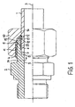
- FIGS. 1 to 3 show a connection arrangement according to the invention, in which a tube 1 is connected to a connecting body 2.
- the FIGS. 1 to 3 will be described together below.
- the connecting arrangement has a longitudinal axis 3, to which the tube 1 and the connecting body 2 are arranged centered.
- the connecting body 2 is provided on its outer surface with a thread 4 that extends from an end face 5. From the end face 5 also assumes a centered on the longitudinal axis 3 conical bore 6, which has a standard opening angle of 24 °.
- This is followed by a first cylindrical bore 7, whose diameter is matched to that of the tube 1.
- the first cylindrical bore 7 terminates in an annular surface 8, from which a diameter-reduced second cylindrical bore 9 continues.
- the tube 1 has a pipe end 36, with which it is inserted into the bore 7.
- the annular surface 8 serves to support the tube 1 against the connecting body 2 in the axial direction.
- a union nut 10 is screwed, which has a bore with a thread 11 which fits the thread 4 of the connecting body 2. Subsequent to the thread 11, a conical bore 12 is provided at the end facing away from the connecting body 2 end of the union nut 10 whose opening angle is standardized and 90 ° and which forms an opposite to the conical bore 6 of the connecting body 2 tapered clamping surface 13 in the form of a conical surface.
- the conical bore 12 of the union nut 10 terminates in a reduced diameter cylindrical bore 14, which is tuned to the outer diameter of the tube 1. The union nut 10 is pushed over the tube 1.
- a support ring 15 is present, the outer surface 16 has a diameter which is sized so large that the union nut 10 can pass it with its thread 11.
- the support ring 15 has a second holding surface 17, which rests flat in the mounted state on the end face 5 of the connecting body 2.
- the support ring 15 also has a conical bore 18, which tapers opposite to the conical bore 12 of the union nut 10.
- the opening angle of the conical bore 18 of the support ring 15 is preferably 13.2 ° to 24.6 ° and can therefore the standardized cone angle of 24 ° of the connecting body 2 correspond.
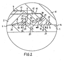
- the tube 1, the conical bore 6 of the connecting body 2 and a first holding surface 37 of the support ring 15 together form a receiving space 32 for receiving a sealing ring 33.
- the sealing ring 33 may be formed as a separate ring or with the support ring 15, for. be firmly connected by vulcanization.
- a cutting ring 19 is provided.
- the cutting ring 19 has a cutting edge portion 20 and a support portion 21.
- the cutting edge portion 20 is conical and received in the tapered bore 18 of the support ring 15.
- the cutting ring 19 has a bore 22 with which it is pushed onto the tube 1.
- the bore 22 is designed in the region of the cutting edge section 20 such that a front cutting edge 23 and a rear cutting edge 24 are formed.
- the support portion 21 is arranged to the union nut 10.
- the support portion 21 forms a cone-shaped pressing surface 25 which is adapted to the conical bore 12 of the union nut 10 and is in abutment with this.
- the cutting ring 19 is acted upon by screwing the union nut 10 on the connecting body 2 axially with force and forms a Bundauf tone 34 in the outer surface of the tube 1. against this, the cutting ring 19 is axially supported in the assembled state of the connection assembly. As a result, the tube 1 is axially supported against the cutting ring 19 and this against the nut 10, so that the tube 1 can not be pulled out of the connector body 2.
- the geometry of the cutting ring 19, that is, the thickness of the cutting edge portion 20, the opening angle of the conical surface 35 of the cutting ring 19 in the region of the cutting edge portion 20 and the inner diameter of the cutting ring 19 in the unassembled and undeformed state relative to the outer diameter of the tube 1, is such designed that with a sufficient depth of cut of the cutting ring 19 of the collar Auf scheme 34 has an outer diameter which is greater than the smallest inner diameter of the support ring 15.
- the Bundaufsch 34th is in this case arranged between the pipe end 36 and the first holding surface 37. The support ring 15 is held with its first holding surface 37 in abutment with the Bundaufschsch 34.
- the cutting ring 19 terminates at least axially flush with the first holding surface 37 of the support ring. It is therefore also possible that the cutting edge portion 20 protrudes with the first holding surface 37 from the tapered bore 18 of the support ring 15 in the direction of the tube end 36. This ensures that the support ring 15 after proper assembly and disassembly of the connection assembly in a visual inspection of the depth of cut of the cutting ring 19 can not slip from the tube 1.
- the geometry of the cutting ring 19 should be designed such that at an insufficient depth of cut of the cutting ring 19, the collar Auf scheme 34 has an outer diameter which is smaller than the smallest inner diameter of the support ring 15 so that the support ring 15 across the Bundaufmine away to the pipe end 36 can be moved towards and can be removed from the tube 1.
- the support portion 21 further forms a first support surface 26, which faces the support ring 15 and is represented by a circumferential undercut 27.
- the first support surface 26 opens in the shape of a cone in the direction of the support ring 15.
- the support ring 15 forms a second support surface 28, which is also cone-shaped and has the same opening angle as the first support surface 26.
- the second support surface 28 is formed by a circumferential projection 29 of the support ring 15, which received in the undercut 27 of the cutting ring 19 is.
- the first support surface 26 is supported against the second support surface 28. Due to the conical configuration of the support surfaces 26, 28 of the cutting ring 19 is supported radially against deformation in the direction of the longitudinal axis 3 against deformation.
- the first support surface 26 also provides a first stop surface and the second support surface 28 is a second stop surface, wherein the cutting ring 19 to limit the assembly path, ie the path over which the cutting ring 19 cuts into the tube 1, with the first stop surface 26 axially against the second stop surface 28 of the support ring 15 is supported.
- the support ring 15 also has a holding portion 30, with which the support ring 15 is immersed in the conical bore 6 of the connecting body 2 and extends over part of the length of the conical bore 6.
- the holding portion 30 has an outer surface 31, which is also cone-shaped and is adapted to the conical bore 6 of the connecting body 2.
- the cutting edge portion 20 of the cutting ring 19 dips into the conical bore 18 of the support ring 15 so deep that it extends into the conical bore 6 of the connecting body 2.
- the front cutting edge 23 is formed on the end of the cutting edge portion 20 dipping into the tapered hole 6 of the connecting body 2, so that it is supported radially against the connecting body 2 via the holding portion 30.
- the rear cutting edge 24 is disposed within the support ring 15 and outside the cone bore 6 of the connecting body 2.
- the holding portion 30 also serves to clamp the support ring 15 on the outer surface 31 of the holding portion 30 in the conical bore 6 of the connecting body 2, so that the frictional force between the connecting body 2 and the support ring 15 is greater than between the cutting ring 19 and the union nut 10th Further, the frictional force between the support ring 15 and the cutting ring 19 is greater than between the cutting ring 19 and the union nut 10, so that when tightening the nut 10, this rotates relative to the cutting ring 19 and not the cutting ring 19 relative to the support ring 15 or the support ring 15 relative to the connecting body 2. Thus, it is effectively avoided that when tightening the nut 10, the tube 1 rotates together with the nut 10.
- the radial support of the cutting ring 19 relative to the support ring 15 prevents radial deformation of the cutting ring 19 and thus a constriction of the tube 1. This results in higher bursting pressures of the connection arrangement, since the tube 1 is loaded less. Furthermore, the mounting end is indicated by a significant torque increase.
Landscapes
- Engineering & Computer Science (AREA)
- General Engineering & Computer Science (AREA)
- Mechanical Engineering (AREA)
- Joints With Pressure Members (AREA)
- Branch Pipes, Bends, And The Like (AREA)
Description
Die Erfindung betrifft eine Verbindungsanordnung zum Verbinden eines Rohres oder Rohrstutzens mit einem Verbindungskörper, der eine von einer Stirnfläche sich verjüngende Kegelbohrung aufweist, wobei die Verbindungsanordnung eine Längsachse, einen Stützring, der ausgehend von einer ersten Haltefläche eine sich in derselben Richtung wie die Kegelbohrung des Verbindungskörpers erweiternde Kegelbohrung aufweist und der mit einer zweiten Haltefläche gegen die Stirnfläche des Verbindungskörpers abgestützt ist, eine Überwurfmutter, die auf ein Gewinde des Verbindungskörpers aufschraubbar ist und die eine Spannfläche bildet, sowie einen Schneidring, der in der Kegelbohrung des Stützrings sitzt und eine Pressfläche zur Kraftbeaufschlagung durch die Spannfläche der Überwurfmuter aufweist.The invention relates to a connection arrangement for connecting a pipe or pipe socket with a connecting body having a conical bore tapering from an end face, the connecting arrangement having a longitudinal axis, a supporting ring extending from a first holding surface in the same direction as the conical bore of the connecting body has flared tapered bore and which is supported with a second retaining surface against the end face of the connecting body, a union nut which is screwed onto a thread of the connecting body and which forms a clamping surface, and a cutting ring which sits in the tapered bore of the support ring and a pressing surface for applying force has by the clamping surface of the union nut.
Eine solche Verbindungsanordnung ist aus der
Die
Die
Die
Eine Verbindungsanordnung die eine Überwurfmutter und Schneidring aufweist, aber auf einen Stützring verzichtet, zeigt die
Bei Verbindungsanordnungen der eingangs genannten Art wird der Schneidring durch Aufschrauben der Überwurfmutter auf den Verbindungskörper axial mit Kraft beaufschlagt und bildet einen Bundaufwurf in der Außenfläche des Rohres. Gegen diesen ist der Schneidring im montierten Zustand der Verbindungsanordnung axial abgestützt. Hierdurch ist das Rohr axial gegen den Schneidring und dieser gegen die Überwurfmutter abgestützt, so dass das Rohr nicht aus dem Verbindungskörper gezogen werden kann. Für eine zuverlässige Verbindung ist es daher wichtig, dass der Schneidring tief genug in das Rohr einschneidet, um das Rohr sicher zu halten.In connection arrangements of the type mentioned above, the cutting ring is axially acted upon by screwing the union nut on the connecting body with force and forms a collar Aufwurf in the outer surface of the tube. Against this, the cutting ring is axially supported in the assembled state of the connection assembly. As a result, the tube is supported axially against the cutting ring and this against the union nut, so that the tube can not be pulled out of the connecting body. For a reliable connection, it is therefore important that the cutting ring cuts deeply enough into the tube to hold the tube securely.
Hierzu ist es üblich, dass die Verbindungsanordnung zunächst vorschriftsmäßig montiert wird. Danach wird die Überwurfmutter wieder von dem Verbindungskörper abgeschraubt und das Rohrende aus dem Verbindungskörper entfernt. Die Schnitttiefer des Schneidrings unterliegt dann einer Sichtkontrolle des Monteurs, der beurteilt, ob der Scheidring tief genug in das Rohr eingeschnitten hat, bevor die Verbindungsanordnung wieder montiert wird. Bei der Sichtkontrolle ist es jedoch möglich, dass der Stützring vom Rohrende und somit vom Rohr rutscht, wodurch eine Wiedermontage aufwendiger wird.For this purpose, it is customary that the connection arrangement is initially mounted according to regulations. Thereafter, the union nut is unscrewed from the connector body and the tube end removed from the connector body. The cut deeper of the cutting ring then undergoes a visual inspection by the installer who judges whether the cutting ring has cut deeply enough into the pipe before the joint assembly is reassembled. In visual inspection, however, it is possible that the support ring from the pipe end and thus from the pipe slips, making re-assembly is more expensive.
Aufgabe der vorliegenden Erfindung ist es, eine Verbindungsanordnung zu schaffen, bei der die Montage einfacher gestaltet ist.The object of the present invention is to provide a connection arrangement in which the assembly is made simpler.
Die Aufgabe wird erfindungsgemäß durch eine Verbindungsanordnung zum Verbinden eines Rohres mit einem Verbindungskörper, der eine von einer Stirnfläche ausgehende sich verjüngende Kegelbohrung aufweist, umfassend:
- eine Längsachse,
- ein Rohr, das mit einem Rohrende in die Kegelbohrung des Verbindungskörpers einsteckbar ist,
- einen Stützring, der eine sich ausgehend von einer ersten Haltefläche in derselben Richtung wie die Kegelbohrung des Verbindungskörpers erweiternde Kegelbohrung aufweist und der mit einer zweiten Haltefläche gegen die Stirnfläche des Verbindungskörpers abgestützt ist, sowie
- eine Überwurfmutter, die auf ein Gewinde des Verbindungskörpers aufschraubbar ist, die eine Spannfläche bildet und zumindest mittelbar axial gegen den Stützring abgestützt ist,
- einen Schneidring, der in der Kegelbohrung des Stützrings sitzt, der eine Pressfläche zur Kraftbeaufschlagung durch die Spannfläche der Überwurfmutter aufweist und der zumindest eine erste Schneidkante aufweist und
- einen durch Einschneiden der ersten Schneidkante in das Rohr gebildeter Bundaufwurf in der Außenfläche des Rohres, dessen Außendurchmesser größer ist als der kleinste Innendurchmesser des Stützrings und der zwischen dem Rohrende und der ersten Haltefläche angeordnet ist, gelöst.
- a longitudinal axis,
- a tube which can be inserted with a pipe end into the conical bore of the connecting body,
- a support ring having a flared from the first holding surface in the same direction as the conical bore of the connecting body conical bore and having a second holding surface against the end face of the connecting body is supported, as well
- a union nut, which can be screwed onto a thread of the connecting body, which forms a clamping surface and is supported at least indirectly axially against the supporting ring,
- a cutting ring which sits in the conical bore of the support ring having a pressing surface for applying force by the clamping surface of the union nut and which has at least a first cutting edge and
- a Bundaufwurf formed by cutting the first cutting edge into the tube in the outer surface of the tube whose outer diameter is greater than the smallest inner diameter of the support ring and which is arranged between the pipe end and the first holding surface solved.
Die Geometrie des Schneidrings ist derart gestaltet, dass bei einer ausreichenden Schnitttiefe des Schneidrings der Bundaufwurf einen Außendurchmesser aufweist, der größer ist, als der kleinste Innendurchmesser des Stützrings. Somit ist sichergestellt, dass der Stützring nach vorschriftsmäßiger Montage und Demontage der Verbindungsanordnung bei der Sichtkontrolle der Schnitttiefe des Schneidrings nicht vom Rohr rutschen kann.The geometry of the cutting ring is designed such that at a sufficient depth of cut of the cutting ring of the collar throw has an outer diameter which is greater than the smallest inner diameter of the support ring. This ensures that the support ring after proper assembly and disassembly of the connection assembly in the visual inspection of the cutting depth of the cutting ring can not slip from the pipe.
Ferner sollte die Geometrie des Schneidrings derart gestaltet, dass bei einer nicht ausreichenden Schnitttiefe des Schneidrings der Bundaufwurf einen Außendurchmesser aufweist, der kleiner ist, als der kleinste Innendurchmesser des Stützrings, so dass der Stützring über den Bundaufwurf hinweg zum Rohrende hin bewegt werden kann und vom Rohr entfernt werden kann.Furthermore, the geometry of the cutting ring should be designed such that at an insufficient depth of cut of the cutting ring Bundaufwurf has an outer diameter which is smaller than the smallest inner diameter of the support ring, so that the support ring can be moved across the Bundaufwurf away to the pipe end and from Pipe can be removed.
Ob der Schneidring ausreichend tief in das Rohr eingeschnitten hat oder nicht lässt sich dann einfach dadurch feststellen, ob nach Montage und Demontage der Verbindungsanordnung der Stützring auf dem Rohr gehalten ist oder nicht. Lässt er sich nicht über den Bundaufwurf bewegen, ist die Schnitttiefe ausreichend. Lässt er sich über den Bundaufwurf schieben, ist die Schnitttiefe nicht ausreichend.Whether the cutting ring has cut sufficiently deep into the pipe or not can then be determined simply by whether or not after assembly and disassembly of the connection arrangement of the support ring is held on the pipe. If he does not move over the collar throw, the depth of cut is sufficient. If he pushes himself over the collar throw, the depth of cut is not sufficient.
Vorzugsweise ist im montierten Zustand der Verbindungsanordnung der Stützring mit seiner ersten Haltefläche in Anlage zum Bundaufwurf gehalten. Dies kann dadurch erreicht werden, dass der Schneidring axial bündig mit der ersten Haltefläche des Stützrings abschließt. Der Schneidring kann jedoch auch axial in Richtung zum Rohrende aus der Kegelbohrung des Stützrings und somit von der ersten Haltefläche des Stützrings in Richtung zum Rohrende vorstehen.Preferably, in the mounted state of the connection arrangement of the support ring is held with its first holding surface in contact with the Bundaufwurf. This can be done be achieved, that the cutting ring terminates axially flush with the first holding surface of the support ring. However, the cutting ring can also protrude axially in the direction of the tube end from the conical bore of the support ring and thus from the first holding surface of the support ring in the direction of the tube end.
Vorzugsweise weist die Überwurfmutter eine Kegelbohrung auf, die eine sich entgegengesetzt zur Kegelbohrung des Verbindungskörpers verjüngende Spannfläche in Form einer Kegelfläche bildet.The union nut preferably has a conical bore which forms a clamping surface tapering in the opposite direction to the conical bore of the connecting body in the form of a conical surface.
Die Schnitttiefe ist abhängig von dem Kegelwinkel der Kegelbohrung des Stützrings und von der Montagelänge, wobei die Montagelänge die Länge ist, über die der Schneidring in das Rohr einschneidet. Zur Begrenzung und definierten Vorgabe des Montageweges kann daher vorgesehen sein, dass im montierten Zustand der Verbindungsanordnung der Schneidring mit einer ersten Anschlagfläche axial gegen eine zweite Anschlagfläche des Stützrings abgestützt ist.The depth of cut depends on the cone angle of the tapered bore of the support ring and on the mounting length, where the mounting length is the length over which the cutting ring cuts into the pipe. For limitation and defined specification of the mounting path can therefore be provided that in the assembled state of the connection assembly of the cutting ring is axially supported with a first stop surface against a second stop surface of the support ring.
Ferner ist vorzugsweise vorgesehen, dass der Schneidring eine erste Stützfläche aufweist, mittels derer der Schneidring in radialer Richtung auf die Längsachse zu gegen eine zweite Stützfläche des Stützrings abgestützt ist. Hierbei kann die erste Stützfläche die erste Anschlagfläche und die zweite Stützfläche die zweite Anschlagfläche darstellen.Furthermore, it is preferably provided that the cutting ring has a first support surface, by means of which the cutting ring is supported in the radial direction on the longitudinal axis against a second support surface of the support ring. In this case, the first support surface may be the first stop surface and the second support surface may be the second stop surface.
Die Abstützung des Schneidrings gegen den Stützring in radialer Richtung auf die Längsachse zu gewährleistet, dass selbst bei einem Überanzug der Überwurfmutter der Schneidring nicht oder nur geringfügig durch die Kegelfläche der Überwurfmutter radial nach innen verformt wird. Somit wird eine übermäßige Einschnürung des Rohres vermieden. Hierdurch wird die Montagesicherheit erhöht und insbesondere bei dünnwandigen Rohren eine höhere Biegefestigkeit erreicht. Ferner entsteht aufgrund der Tatsache, dass der Schneidring radial nach innen abgestützt ist und nicht nach innen ausweichen kann, bei der Montage ein sehr deutlicher Drehmomentanstieg, der das Montageende anzeigt.Ensuring the support of the cutting ring against the support ring in the radial direction to the longitudinal axis, that even with a cover of the nut of the cutting ring is not or only slightly deformed by the conical surface of the nut radially inward. Thus, excessive constriction of the tube is avoided. As a result, the mounting safety is increased and achieved in particular with thin-walled tubes a higher flexural strength. Further, due to the fact that the cutting ring is supported radially inwardly and can not escape inwardly, a very significant increase in torque during assembly, indicating the end of assembly.
Der Stützring wird bei Übermontage und besonders bei Rohren aus einem hochwertigen Material stark radial nach außen beansprucht und kann aufplatzen. Durch die Abstützung des Schneidrings gegen den Stützring radial nach innen wird bei Montageende eine Kraftkomponente radial nach innen auf den Stützring eingeleitet, wodurch die Gefahr des Aufplatzens reduziert wird.The support ring is made of a high quality when over-mounted and especially for pipes Material strongly stressed radially outward and can burst. By supporting the cutting ring against the support ring radially inwards a force component is introduced radially inwardly on the support ring at the end of assembly, whereby the risk of bursting is reduced.
Bei genormten Überwurfmuttern ist die Spannfläche in Form einer Kegelbohrung mit einem Öffnungswinkel von 90° ausgeführt. Genormte Verbindungskörper weisen eine Kegelbohrung mit einem Öffnungswinkel von 24° auf. In der Regel ist der Öffnungswinkel der Kegelbohrung des Stützrings an den des Verbindungskörpers angepasst und beträgt somit ebenfalls 24°. Da es sich bei dem Stützring jedoch nicht um ein Normteil handelt, kann dieser Winkel angepasst werden, um gegebenenfalls die Einschnitttiefe des Schneidrings in das Rohr anzupassen. Hierdurch lässt sich zudem der Außendurchmesser des Bundaufwurfs anpassen. Der Öffnungswinkel beträgt vorzugsweise 13,2° bis 24,6°. Bei einer bevorzugten Dicke eines Schneidkantenabschnitts des Schneidrings, der die Schneidkante bildet, von 0,22 mm bis 0,58 mm wird somit eine Schnitttiefe von 0,05 mm bis 0,26 mm erreicht.For standardized union nuts, the clamping surface is designed in the form of a conical bore with an opening angle of 90 °. Standardized connecting bodies have a conical bore with an opening angle of 24 °. In general, the opening angle of the tapered bore of the support ring is adapted to that of the connecting body and is therefore also 24 °. However, since the support ring is not a standard part, this angle can be adjusted to adjust, if necessary, the depth of cut of the cutting ring in the pipe. This also allows the outer diameter of the Bundaufwurfs customize. The opening angle is preferably 13.2 ° to 24.6 °. Thus, with a preferred thickness of a cutting edge portion of the cutting ring forming the cutting edge of 0.22 mm to 0.58 mm, a cutting depth of 0.05 mm to 0.26 mm is achieved.
Der Schneidring weist vorzugsweise einen Stützabschnitt und einen Schneidkantenabschnitt aufweisen, wobei der Stützabschnitt die erste Stützfläche bildet und der Schneidkantenabschnitt in der Kegelbohrung des Stützrings aufgenommen ist.The cutting ring preferably has a support portion and a cutting edge portion, wherein the support portion forms the first support surface and the cutting edge portion is received in the tapered bore of the support ring.
Die Stützflächen können konisch gestaltet sein. Vorzugsweise ist die erste Stützfläche durch einen umlaufenden Hinterschnitt des Schneidrings und die zweite Stützfläche durch einen umlaufenden Vorsprung des Stützrings gebildet. Hierbei wird der umlaufende Vorsprung im Hinterschnitt aufgenommen.The support surfaces can be conical. Preferably, the first support surface is formed by a circumferential undercut of the cutting ring and the second support surface by a circumferential projection of the support ring. Here, the circumferential projection is added in the undercut.
Der Stützring kann über einen Teil der Länge der Kegelbohrung des Verbindungskörpers in diese hineinragen, so dass die erste Haltefläche in der Kegelbohrung des Verbindungskörpers angeordnet ist. Hierdurch erfährt der Stützring, der stark radial nach außen beansprucht ist, eine Abstützung radial nach außen.The support ring can protrude over a part of the length of the conical bore of the connecting body in this, so that the first holding surface is arranged in the conical bore of the connecting body. As a result, the support ring, which is strongly stressed radially outwards, experiences a support radially outward.
Vorzugsweise verläuft dann der Schneidkantenabschnitt bis in die Kegelbohrung des Verbindungskörpers hinein. Somit ist gewährleistet, dass der Schneidkantenabschnitt indirekt über den in die Kegelbohrung des Verbindungskörpers hineinragenden Stützring radial gegen den Verbindungskörper abgestützt ist. Hierbei kann eine Schneidkante des Schneidrings innerhalb der Kegelbohrung des Verbindungskörpers angeordnet sein, die somit radial abgestützt ist.Preferably, the cutting edge section then extends into the conical bore of the connecting body. This ensures that the cutting edge section is supported radially against the connecting body via the projecting into the conical bore of the connecting body support ring. In this case, a cutting edge of the cutting ring can be arranged within the conical bore of the connecting body, which is thus radially supported.
Vorzugweise weist der Schneidring zwei Schneidkanten auf. Hierbei kann einer der Schneidkanten innerhalb der Kegelbohrung des Verbindungskörpers und die andere Schneidkante außerhalb der Kegelbohrung des Verbindungskörpers angeordnet sein.Preferably, the cutting ring has two cutting edges. In this case, one of the cutting edges can be arranged inside the conical bore of the connecting body and the other cutting edge outside the conical bore of the connecting body.
Durch die Kegelbohrung des Verbindungskörpers, den Stützring und das Rohr kann ein Aufnahmeraum gebildet sein, in dem ein Dichtring aufgenommen ist.Through the conical bore of the connecting body, the support ring and the tube can be formed a receiving space in which a sealing ring is received.
Die Überwurfmutter kann im montierten Zustand der Verbindungsanordnung mittelbar über den Schneidring gegen den Stützring axial abgestützt sein. Hierzu kann vorgesehen sein, dass die Überwurfmutter mit ihrer Spannfläche axial gegen die Pressfläche des Schneidrings abgestützt ist und dass der Schneidring mit einer ersten Stützfläche axial gegen eine zweite Stützfläche des Stützrings abgestützt ist.The union nut may be axially supported indirectly via the cutting ring against the support ring in the assembled state of the connection arrangement. For this purpose, it may be provided that the union nut is axially supported with its clamping surface against the pressing surface of the cutting ring and that the cutting ring is axially supported with a first support surface against a second support surface of the support ring.
Alternativ kann vorgesehen sein, dass im montierten Zustand der Verbindungsanordnung die Spannfläche der Überwurfmutter sowohl unmittelbar gegen die zweite Stützfläche des Stützrings als auch gegen die Pressfläche des Schneidrings axial abgestützt ist.Alternatively it can be provided that in the assembled state of the connection arrangement, the clamping surface of the union nut is axially supported both directly against the second support surface of the support ring and against the pressing surface of the cutting ring.
Ein bevorzugtes Ausführungsbeispiel wird im folgenden anhand der Zeichnungen näher erläutert. Hierin zeigt
- Figur 1
- einen Längsschnitt einer erfindungsgemäßen Verbindungsanordnung im montierten Zustand,
Figur 2- einen vergrößert dargestellten Ausschnitt der Verbindungsanordnung gemäß
Figur 1 und Figur 3- eine vergrößert dargestellten Ausschnitt des Bundaufwurfs gemäß
Figur 1 .
- FIG. 1
- a longitudinal section of a connecting arrangement according to the invention in the mounted state,
- FIG. 2
- an enlarged detail of the connection arrangement according to FIG
FIG. 1 and - FIG. 3
- an enlarged section of the Bundaufwurfs according to
FIG. 1 ,
Die
Auf den Verbindungskörper 2 ist eine Überwurfmutter 10 aufgeschraubt, welche eine Bohrung mit einem Gewinde 11 besitzt, das zum Gewinde 4 des Verbindungskörpers 2 passt. Im Anschluss an das Gewinde 11 ist am vom Verbindungskörper 2 abgewandten Ende der Überwurfmutter 10 eine Kegelbohrung 12 vorgesehen, deren Öffnungswinkel genormt ist und 90° beträgt und welche eine sich entgegen gesetzte zur Kegelbohrung 6 des Verbindungskörpers 2 verjüngende Spannfläche 13 in Form einer Kegelfläche bildet. Die Kegelbohrung 12 der Überwurfmutter 10 endet in einer im Durchmesser reduzierten zylindrischen Bohrung 14, die auf den Außendurchmesser des Rohres 1 abgestimmt ist. Die Überwurfmutter 10 ist über das Rohr 1 geschoben.On the connecting
Ferner ist ein Stützring 15 vorhanden, dessen Außenfläche 16 einen Durchmesser aufweist, der so groß bemessen ist, dass die Überwurfmutter 10 ihn mit ihrem Gewinde 11 passieren kann. Der Stützring 15 besitzt eine zweite Haltefläche 17, die im montierten Zustand flächig an der Stirnfläche 5 des Verbindungskörpers 2 anliegt. Der Stützring 15 weist ferner eine Kegelbohrung 18 auf, die sich entgegengesetzt zur Kegelbohrung 12 der Überwurfmutter 10 verjüngt. Der Öffnungswinkel der Kegelbohrung 18 des Stützrings 15 beträgt vorzugsweise 13,2° bis 24,6° und kann demnach dem genormten Kegelwinkel von 24° des Verbindungskörpers 2 entsprechen.Further, a
Das Rohr 1, die Kegelbohrung 6 des Verbindungskörpers 2 und eine erste Haltefläche 37 des Stützrings 15 bilden zusammen einen Aufnahmeraum 32 zur Aufnahme eines Dichtrings 33. Der Dichtring 33 kann als separater Ring ausgebildet sein oder mit dem Stützring 15 z.B. durch Anvulkanisieren fest verbunden sein.The tube 1, the
Ferner ist ein Schneidring 19 vorgesehen. Der Schneidring 19 weist einen Schneidkantenabschnitt 20 sowie einen Stützabschnitt 21 auf. Der Schneidkantenabschnitt 20 ist konisch gestaltet und in der Kegelbohrung 18 des Stützrings 15 aufgenommen. Der Schneidring 19 weist eine Bohrung 22 auf, mit der er auf das Rohr 1 aufgeschoben ist. Die Bohrung 22 ist im Bereich des Schneidkantenabschnitt 20 derart gestalte, dass eine vordere Schneidkante 23 und eine hintere Schneidkante 24 gebildet sind.Further, a cutting
Der Stützabschnitt 21 ist zur Überwurfmutter 10 hin angeordnet. Der Stützabschnitt 21 bildet eine konusförmige Pressfläche 25, die an die Kegelbohrung 12 der Überwurfmutter 10 angepasst ist und zu dieser in Anlage ist.The
Der Schneidring 19 wird durch Aufschrauben der Überwurfmutter 10 auf den Verbindungskörper 2 axial mit Kraft beaufschlagt und bildet einen Bundaufwurf 34 in der Außenfläche des Rohres 1. Gegen diesen ist der Schneidring 19 im montierten Zustand der Verbindungsanordnung axial abgestützt. Hierdurch ist das Rohr 1 axial gegen den Schneidring 19 und dieser gegen die Überwurfmutter 10 abgestützt, so dass das Rohr 1 nicht aus dem Verbindungskörper 2 gezogen werden kann.The cutting
Die Geometrie des Schneidrings 19, das heißt die Dicke des Schneidkantenabschnitts 20, der Öffnungswinkel der Kegelfläche 35 des Schneidrings 19 im Bereich des Schneidkantenabschnitts 20 sowie der Innendurchmesser des Schneidrings 19 im nicht montierten und nicht deformierten Zustand im Verhältnis zum Außendurchmesser des Rohres 1, ist derart gestaltet, dass bei einer ausreichenden Schnitttiefe des Schneidrings 19 der Bundaufwurf 34 einen Außendurchmesser aufweist, der größer ist, als der kleinste Innendurchmesser des Stützrings 15. Der Bundaufwurf 34 ist hierbei zwischen dem Rohrende 36 und der ersten Haltefläche 37 angeordnet. Der Stützring 15 ist mit seiner ersten Haltefläche 37 in Anlage zum Bundaufwurf 34 gehalten. Hierzu ist vorgesehen, dass der Schneidring 19 zumindest axial bündig mit der ersten Haltefläche 37 des Stützrings abschließt. Es ist demnach auch möglich, dass der Schneidkantenabschnitt 20 mit der ersten Haltefläche 37 aus der Kegelbohrung 18 des Stützrings 15 in Richtung zum Rohrende 36 vorragt. Somit ist sichergestellt, dass der Stützring 15 nach vorschriftsmäßiger Montage und Demontage der Verbindungsanordnung bei einer Sichtkontrolle der Schnitttiefe des Schneidrings 19 nicht vom Rohr 1 rutschen kann.The geometry of the cutting
Ferner sollte die Geometrie des Schneidrings 19 derart gestaltet sein, dass bei einer nicht ausreichenden Schnitttiefe des Schneidrings 19 der Bundaufwurf 34 einen Außendurchmesser aufweist, der kleiner ist, als der kleinste Innendurchmesser des Stützrings 15, so dass der Stützring 15 über den Bundaufwurf hinweg zum Rohrende 36 hin bewegt werden kann und vom Rohr 1 entfernt werden kann.Furthermore, the geometry of the cutting
Der Stützabschnitt 21 bildet ferner eine erste Stützfläche 26, die dem Stützring 15 zugewandt und durch einen umlaufenden Hinterschnitt 27 dargestellt ist. Die erste Stützfläche 26 öffnet sich konusförmig in Richtung zum Stützring 15.The
Der Stützring 15 bildet eine zweite Stützfläche 28, die ebenfalls konusförmig gestalte ist und den gleichen Öffnungswinkel aufweist, wie die erste Stützfläche 26. Die zweite Stützfläche 28 ist durch einen umlaufenden Vorsprung 29 des Stützrings 15 gebildet, der in dem Hinterschnitt 27 des Schneidrings 19 aufgenommen ist. Die erste Stützfläche 26 ist gegen die zweite Stützfläche 28 abgestützt. Durch die konusförmige Ausgestaltung der Stützflächen 26, 28 ist der Schneidring 19 gegen Deformation radial nach innen in Richtung auf die Längsachse 3 zu abgestützt.The
Die erste Stützfläche 26 stellt zudem eine erste Anschlagfläche und die zweite Stützfläche 28 eine zweite Anschlagfläche dar, wobei der Schneidring 19 zur Begrenzung des Montageweges, d. h. des Weges, über den der Schneidring 19 in das Rohr 1 einschneidet, mit der ersten Anschlagfläche 26 axial gegen die zweite Anschlagfläche 28 des Stützrings 15 abgestützt ist.The
Der Stützring 15 weist ferner einen Halteabschnitt 30 auf, mit dem der Stützring 15 in die Kegelbohrung 6 des Verbindungskörpers 2 eintaucht und sich über einen Teil der Länge der Kegelbohrung 6 erstreckt. Der Halteabschnitt 30 weist eine Außenfläche 31 auf, die ebenfalls konusförmig ist und an die Kegelbohrung 6 des Verbindungskörpers 2 angepasst ist. Der Schneidkantenabschnitt 20 des Schneidrings 19 taucht in die Kegelbohrung 18 des Stützrings 15 so tief ein, dass er bis in die Kegelbohrung 6 des Verbindungskörpers 2 verläuft. Die vordere Schneidkante 23 ist an dem in die Kegelbohrung 6 des Verbindungskörpers 2 eintauchenden Ende des Schneidkantenabschnitts 20 ausgebildet, so dass diese radial über den Halteabschnitt 30 gegen den Verbindungskörper 2 abgestützt ist. Die hintere Schneidkante 24 ist innerhalb des Stützrings 15 und außerhalb der Konusbohrung 6 des Verbindungskörpers 2 angeordnet. Somit ergeben sich höherer Berstdrücke der Schneidringverbindung.The
Der Halteabschnitt 30 dient ferner dazu, den Stützring 15 über die Außenfläche 31 des Halteabschnitts 30 in der Kegelbohrung 6 des Verbindungskörpers 2 zu verspannen, so dass die Reibkraft zwischen dem Verbindungskörper 2 und dem Stützring 15 größer ist als zwischen dem Schneidring 19 und der Überwurfmutter 10. Ferner ist die Reibkraft zwischen dem Stützring 15 und dem Schneidring 19 größer als zwischen dem Schneidring 19 und der Überwurfmutter 10, so dass sich beim Anziehen der Überwurfmutter 10 diese relativ zum Schneidring 19 dreht und nicht der Schneidring 19 relativ zum Stützring 15 oder der Stützring 15 relativ zum Verbindungskörper 2. Somit wird wirksam vermieden, dass sich beim Anziehen der Überwurfmutter 10 das Rohr 1 zusammen mit der Überwurfmutter 10 dreht.The holding
Die radiale Abstützung des Schneidrings 19 gegenüber dem Stützring 15 verhindert eine radiale Deformation des Schneidrings 19 und somit eine Einschnürung des Rohrs 1. Hierdurch ergeben sich höhere Berstdrücke der Verbindungsanordnung, da das Rohr 1 geringer belastet wird. Ferner wird das Montageende durch einen deutlichen Drehmomentanstieg angezeigt.The radial support of the cutting
- 11
- Rohrpipe
- 22
- Verbindungskörperconnecting body
- 33
- Längsachselongitudinal axis
- 44
- Gewinde des VerbindungskörpersThread of the connecting body
- 55
- Stirnflächeface
- 66
- Kegelbohrung des VerbindungskörpersConical bore of the connecting body
- 77
- erste zylindrische Bohrungfirst cylindrical bore
- 88th
- Ringflächering surface
- 99
- zweite zylindrische Bohrungsecond cylindrical bore
- 1010
- ÜberwurfmutterNut
- 1111
- Gewinde der ÜberwurfmutterThread of the union nut
- 1212
- Kegelbohrung der ÜberwurfmutterTaper bore of the union nut
- 1313
- Spannflächeclamping surface
- 1414
- zylindrische Bohrungcylindrical bore
- 1515
- Stützringsupport ring
- 1616
- Außenflächeouter surface
- 1717
- zweite Halteflächesecond holding surface
- 1818
- Kegelbohrung des StützringsTaper hole of the support ring
- 1919
- Schneidringcutting ring
- 2020
- SchneidkantenabschnittCutting edge section
- 2121
- Stützabschnittsupport section
- 2222
- Bohrungdrilling
- 2323
- vordere Schneidkantefront cutting edge
- 2424
- hintere Schneidkanterear cutting edge
- 2525
- PressflächePress area
- 2626
- erste Stützflächefirst support surface
- 2727
- Hinterschnittundercut
- 2828
- zweite Stützflächesecond support surface
- 2929
- Vorsprunghead Start
- 3030
- Halteabschnittholding section
- 3131
- Außenflächeouter surface
- 3232
- Aufnahmeraumaccommodation space
- 3333
- Dichtringseal
- 3434
- Bundaufwurfshoulder throw
- 3535
- Kegelfläche des SchneidringsCone surface of the cutting ring
- 3636
- Rohrendepipe end
- 3737
- erste Halteflächefirst holding surface
Claims (16)
- Connecting assembly for connecting a pipe (1) with a connecting element (2) which comprises a conical bore (6) that tapers starting from a face (5), comprising:a longitudinal axis (3); a pipe (1) having a pipe end (36) that can be inserted into the conical bore (6) of the connecting element (2);a supporting ring (15) having a conical bore starting from a first retaining surface (37) and flaring in the same direction as the conical bore (6) of the connecting element (2) and having a second retaining surface (17) being supported by the face (5) of the connecting element (2);a union nut (10) which can be screwed on a thread (4) of the connecting element (2) and which forms a tensioning surface (13) and is supported axially at least indirectly on the supporting ring (15);a cutting ring (19) seated in the conical bore (18) of the supporting ring (15) and provided with a pressure surface (25) for the impingement of force by the tensioning surface (13) of the union nut (10), and having at least one first cutting edge (23), whereas the connecting assembly is characterized in thata collar bulge (34) on the outer surface of the pipe (1) formed by cutting the first cutting edge (23) into the pipe (1), said collar bulge's outside diameter being greater than the smallest inside diameter of the supporting ring (15) and said collar bulge being located between the pipe end (36) and the first retaining surface (37).
- Connecting assembly in accordance with Claim 1,
characterized in that
the first retaining surface (37) of the supporting ring (15) is in abutment with the collar bulge (34). - Connecting assembly in accordance with one of the Claims 1 or 2,
characterized in that
the cutting ring (19) is axially flush adjoining the first retaining surface (37) of the supporting ring (15)or projects axially in the direction of the pipe end (36). - Connecting assembly in accordance with one of the Claims 1 through 3,
characterized in that,
in order to limit the assembly path, the cutting ring (19) abuts with a first abutment surface (26) axially against a second abutment surface (28) of the supporting ring (15). - Connecting assembly in accordance with one of the Claims 1 through 4,
characterized in that,
the cutting ring (19) comprises a first supporting surface (26) by means of which the cutting ring (19) is supported in radial direction toward the longitudinal axis (3) against a second supporting surface (28) of the supporting ring . - Connecting assembly in accordance with Claim 5,
characterized in that,
the first supporting surface (26) represents a first abutment surface, and the second supporting surface (28) represents a second abutment surface, whereby the cutting ring (19), in order to limit the assembly path, is supported with the first abutment surface axially against the second abutment surface of the supporting ring (15). - Connecting assembly in accordance with one of the Claims 5 or 6,
characterized in that
the cutting ring (19) has a supporting section (21) and a cutting edge section (20), whereby the supporting section (21) represents the first supporting section (26), and whereby the cutting edge section (20) is accommodated in the conical bore (18) of the supporting ring (15). - Connecting assembly in accordance with one of the Claims 5 through 7,
characterized in that
the supporting surfaces (26, 28) are conical. - Connecting assembly in accordance with one of the Claims 5 through 8,
characterized in that
the first supporting surface (26) is formed by a peripheral undercut (27) of the cutting ring (19), and the second supporting surface (28) is formed by a peripheral projection (29) of the supporting ring (15). - Connecting assembly in accordance with one of the Claims 1 through 9,
characterized in that
the supporting ring (15) projects over part of the length of the conical bore (6) of the connecting element (2) into said connecting element, and thus the first retaining surface (37) is located in the conical bore (6) of the connecting element (2). - Connecting assembly in accordance with one of the Claims 1 through 10,
characterized in that
the cutting edge section (20) extends into the conical bore (6) of the connecting element (2). - Connecting assembly in accordance with Claim 11,
characterized in that
the first cutting edge (23) is located inside the conical bore (6) of the connecting element (2). - Connecting assembly in accordance with one of the Claims 1 through 12,
characterized in that
the cutting ring (19) comprises a second cutting edge (24) in addition to the first cutting edge (23). - Connecting assembly in accordance with one of the Claims 1 through 13,
characterized in that
the union nut (10) is indirectly axially supported against the supporting ring (15) via the cutting ring (19). - Connecting assembly in accordance with Claim 14,
characterized in that
the tensioning surface (13) of the union nut (10) is axially supported against the pressure surface (25) of the cutting ring (19), and that the first supporting surface (26) of the cutting ring (19) is axially supported against a second supporting surface (28) of the supporting ring (15). - Connecting assembly in accordance with one of the Claims 1 through 13,
characterized in that
the tensioning surface (13) of the union nut (10) is axially supported against the second supporting surface (28) of the supporting ring (15) as well as against the pressure surface (25) of the cutting ring (19).
Applications Claiming Priority (2)
| Application Number | Priority Date | Filing Date | Title |
|---|---|---|---|
| DE102006012493A DE102006012493B3 (en) | 2006-03-16 | 2006-03-16 | Connecting assembly for connecting pipe, has connecting element, with conical bore, which tapers starting from face, and has a longitudinal axis, union nut, which can be screwed onto thread of connecting element |
| PCT/EP2007/001988 WO2007104462A1 (en) | 2006-03-16 | 2007-03-08 | Connecting assembly |
Publications (2)
| Publication Number | Publication Date |
|---|---|
| EP2002166A1 EP2002166A1 (en) | 2008-12-17 |
| EP2002166B1 true EP2002166B1 (en) | 2010-05-19 |
Family
ID=38056311
Family Applications (1)
| Application Number | Title | Priority Date | Filing Date |
|---|---|---|---|
| EP07711848A Active EP2002166B1 (en) | 2006-03-16 | 2007-03-08 | Connecting assembly |
Country Status (6)
| Country | Link |
|---|---|
| US (1) | US20100007143A1 (en) |
| EP (1) | EP2002166B1 (en) |
| JP (1) | JP4968548B2 (en) |
| DE (1) | DE102006012493B3 (en) |
| ES (1) | ES2346094T3 (en) |
| WO (1) | WO2007104462A1 (en) |
Cited By (1)
| Publication number | Priority date | Publication date | Assignee | Title |
|---|---|---|---|---|
| CN102889439A (en) * | 2011-07-21 | 2013-01-23 | 贵州工信机电科技有限公司 | Hydraulic pipe joint sleeve |
Families Citing this family (4)
| Publication number | Priority date | Publication date | Assignee | Title |
|---|---|---|---|---|
| CA2690280A1 (en) * | 2007-06-18 | 2008-12-24 | Weidmann Ltd. | Connecting arrangement for a pipe union |
| JP5457094B2 (en) * | 2009-07-15 | 2014-04-02 | 株式会社キッツ | Plastic pipe fittings |
| DE102016205353A1 (en) | 2016-03-31 | 2017-10-05 | Mahle International Gmbh | The stacked-plate heat exchanger |
| DE102018115479B4 (en) | 2018-06-27 | 2022-02-10 | Voss Fluid Gmbh | Cutting ring screw connection with visual control of the assembly result |
Family Cites Families (11)
| Publication number | Priority date | Publication date | Assignee | Title |
|---|---|---|---|---|
| US3250550A (en) * | 1964-02-13 | 1966-05-10 | Gilbert T Lyon | Self-flaring tube coupling |
| CH441895A (en) * | 1965-07-15 | 1967-08-15 | Fischer Ag Georg | Smooth tube screw connection for plastic tubes |
| BE795528A (en) * | 1971-02-16 | 1973-06-18 | Crawford Cullen B | TUBE JUNCTION FITTING |
| US3893716A (en) * | 1974-04-01 | 1975-07-08 | Weatherhead Co | Flareless fitting |
| FR2461186A1 (en) * | 1979-07-06 | 1981-01-30 | Legris | IMPROVEMENTS IN PIPE FITTINGS, IN PARTICULAR FOR HIGH PRESSURE FLUID PIPES |
| DE4038539C1 (en) * | 1990-12-03 | 1992-04-30 | Parker-Ermeto Gmbh, 4800 Bielefeld, De | |
| DE4311280C2 (en) * | 1993-04-06 | 1997-04-24 | Schwer Fittings Gmbh | Process for producing a cutting ring and cutting ring |
| DE19637129C2 (en) * | 1995-10-30 | 1999-01-28 | Walterscheid Gmbh Jean | Connection for connecting pipes to a connecting body |
| DE19727149C2 (en) * | 1997-06-26 | 2002-10-24 | Voss Fluid Gmbh & Co Kg | Pipe fitting with cutting ring |
| JP2003232474A (en) * | 2002-02-08 | 2003-08-22 | Nasco Fitting Kk | Pipe joint |
| FR2855863B1 (en) * | 2003-06-03 | 2006-12-15 | Legris Sa | CONNECTING DEVICE FOR HIGH PRESSURE FLUID PIPES |
-
2006
- 2006-03-16 DE DE102006012493A patent/DE102006012493B3/en not_active Expired - Lifetime
-
2007
- 2007-03-08 US US12/293,174 patent/US20100007143A1/en not_active Abandoned
- 2007-03-08 WO PCT/EP2007/001988 patent/WO2007104462A1/en not_active Ceased
- 2007-03-08 JP JP2008558685A patent/JP4968548B2/en not_active Expired - Fee Related
- 2007-03-08 ES ES07711848T patent/ES2346094T3/en active Active
- 2007-03-08 EP EP07711848A patent/EP2002166B1/en active Active
Cited By (1)
| Publication number | Priority date | Publication date | Assignee | Title |
|---|---|---|---|---|
| CN102889439A (en) * | 2011-07-21 | 2013-01-23 | 贵州工信机电科技有限公司 | Hydraulic pipe joint sleeve |
Also Published As
| Publication number | Publication date |
|---|---|
| DE102006012493B3 (en) | 2007-06-14 |
| EP2002166A1 (en) | 2008-12-17 |
| JP2009529637A (en) | 2009-08-20 |
| US20100007143A1 (en) | 2010-01-14 |
| WO2007104462A1 (en) | 2007-09-20 |
| JP4968548B2 (en) | 2012-07-04 |
| ES2346094T3 (en) | 2010-10-08 |
Similar Documents
| Publication | Publication Date | Title |
|---|---|---|
| DE4041679C2 (en) | Tube Fitting | |
| DE19740144C2 (en) | Connection of a metal tube with a metal sleeve, and method for producing the connection | |
| DE4304241C2 (en) | Plug connection for pipes, hoses or round bodies | |
| EP0845092A1 (en) | High-pressure connection system | |
| DE3602499A1 (en) | CLUTCH NIPPLE | |
| DE60204157T2 (en) | SUPPORT SLEEVE FOR USE IN A TUBE COUPLING AND CLUTCH HOUSING FOR USE WITH THE SLEEVE | |
| DE3428260A1 (en) | PIPE CONNECTION | |
| EP2872811A1 (en) | Pipe connection | |
| EP2002166B1 (en) | Connecting assembly | |
| DE10107246C5 (en) | Pipe arrangement and pipe element | |
| DE10234615A1 (en) | Flare fitting assembly used in transport of pressurized liquid or gas, has line seal formed between inner surface of flared end of tube and arcuate seating surface when two coupling portions are connected | |
| DE102004052390B4 (en) | Press connection with multiple functions | |
| EP0713042A1 (en) | Pipe joint, especially for pipes with at least one plastic layer | |
| EP1857724B1 (en) | Pipe joint with a deformed pipe | |
| EP1347227B1 (en) | Coupling device for corrugated metal hose | |
| DE10207201A1 (en) | Connecting sleeve fits over pipe and has circumferential groove containing metal clamping ring | |
| EP2008011B1 (en) | Connector for piping, in particular plastic piping | |
| DE60022825T2 (en) | Detachable pipe coupling | |
| EP1770320B1 (en) | Releasable plug-in coupling for pipes | |
| WO2006084766A1 (en) | Connecting assembly | |
| CH701495A1 (en) | A method of connecting a connector with a heat-insulated pipe. | |
| DE102008057448A1 (en) | Pipe connection and process for its production | |
| EP1731817B1 (en) | Pipe connection with deformed pipe | |
| DE102004010603B4 (en) | clamping device | |
| DE10026083C1 (en) | Pipe compression joint has cylindrical metal compression fitting element clamped to inserted pipe end via pressure ring engaged by compression tool |
Legal Events
| Date | Code | Title | Description |
|---|---|---|---|
| PUAI | Public reference made under article 153(3) epc to a published international application that has entered the european phase |
Free format text: ORIGINAL CODE: 0009012 |
|
| AK | Designated contracting states |
Kind code of ref document: A1 Designated state(s): ES FR GB IT |
|
| 17P | Request for examination filed |
Effective date: 20080725 |
|
| 17Q | First examination report despatched |
Effective date: 20090120 |
|
| DAX | Request for extension of the european patent (deleted) | ||
| RBV | Designated contracting states (corrected) |
Designated state(s): ES FR GB IT |
|
| GRAP | Despatch of communication of intention to grant a patent |
Free format text: ORIGINAL CODE: EPIDOSNIGR1 |
|
| GRAS | Grant fee paid |
Free format text: ORIGINAL CODE: EPIDOSNIGR3 |
|
| GRAA | (expected) grant |
Free format text: ORIGINAL CODE: 0009210 |
|
| AK | Designated contracting states |
Kind code of ref document: B1 Designated state(s): ES FR GB IT |
|
| REG | Reference to a national code |
Ref country code: GB Ref legal event code: FG4D Free format text: NOT ENGLISH |
|
| REG | Reference to a national code |
Ref country code: ES Ref legal event code: FG2A Ref document number: 2346094 Country of ref document: ES Kind code of ref document: T3 |
|
| PLBE | No opposition filed within time limit |
Free format text: ORIGINAL CODE: 0009261 |
|
| STAA | Information on the status of an ep patent application or granted ep patent |
Free format text: STATUS: NO OPPOSITION FILED WITHIN TIME LIMIT |
|
| 26N | No opposition filed |
Effective date: 20110222 |
|
| REG | Reference to a national code |
Ref country code: FR Ref legal event code: PLFP Year of fee payment: 10 |
|
| REG | Reference to a national code |
Ref country code: FR Ref legal event code: PLFP Year of fee payment: 11 |
|
| REG | Reference to a national code |
Ref country code: FR Ref legal event code: PLFP Year of fee payment: 12 |
|
| REG | Reference to a national code |
Ref country code: GB Ref legal event code: 732E Free format text: REGISTERED BETWEEN 20210624 AND 20210630 |
|
| REG | Reference to a national code |
Ref country code: ES Ref legal event code: PC2A Owner name: EATON INTELLIGENT POWER LIMITED Effective date: 20210806 |
|
| REG | Reference to a national code |
Ref country code: GB Ref legal event code: 732E Free format text: REGISTERED BETWEEN 20211210 AND 20211215 |
|
| REG | Reference to a national code |
Ref country code: ES Ref legal event code: PC2A Owner name: DANFOSS POWER SOLUTIONS II TECHNOLOGY A/S Effective date: 20220607 |
|
| P01 | Opt-out of the competence of the unified patent court (upc) registered |
Effective date: 20230617 |
|
| REG | Reference to a national code |
Ref country code: ES Ref legal event code: PC2A Owner name: DANFOSS A/S Effective date: 20240416 |
|
| PGFP | Annual fee paid to national office [announced via postgrant information from national office to epo] |
Ref country code: ES Payment date: 20250404 Year of fee payment: 19 |
|
| PGFP | Annual fee paid to national office [announced via postgrant information from national office to epo] |
Ref country code: GB Payment date: 20260209 Year of fee payment: 20 |
|
| PGFP | Annual fee paid to national office [announced via postgrant information from national office to epo] |
Ref country code: IT Payment date: 20260220 Year of fee payment: 20 |
|
| PGFP | Annual fee paid to national office [announced via postgrant information from national office to epo] |
Ref country code: FR Payment date: 20260223 Year of fee payment: 20 |