EP2002156B1 - Verfahren zum betreiben eines automatgetriebes - Google Patents
Verfahren zum betreiben eines automatgetriebes Download PDFInfo
- Publication number
- EP2002156B1 EP2002156B1 EP07712326.3A EP07712326A EP2002156B1 EP 2002156 B1 EP2002156 B1 EP 2002156B1 EP 07712326 A EP07712326 A EP 07712326A EP 2002156 B1 EP2002156 B1 EP 2002156B1
- Authority
- EP
- European Patent Office
- Prior art keywords
- automatic transmission
- closed
- transmission
- gear
- neutral position
- Prior art date
- Legal status (The legal status is an assumption and is not a legal conclusion. Google has not performed a legal analysis and makes no representation as to the accuracy of the status listed.)
- Active
Links
Images
Classifications
-
- F—MECHANICAL ENGINEERING; LIGHTING; HEATING; WEAPONS; BLASTING
- F16—ENGINEERING ELEMENTS AND UNITS; GENERAL MEASURES FOR PRODUCING AND MAINTAINING EFFECTIVE FUNCTIONING OF MACHINES OR INSTALLATIONS; THERMAL INSULATION IN GENERAL
- F16H—GEARING
- F16H61/00—Control functions within control units of change-speed- or reversing-gearings for conveying rotary motion ; Control of exclusively fluid gearing, friction gearing, gearings with endless flexible members or other particular types of gearing
- F16H61/20—Preventing gear creeping ; Transmission control during standstill, e.g. hill hold control
-
- F—MECHANICAL ENGINEERING; LIGHTING; HEATING; WEAPONS; BLASTING
- F16—ENGINEERING ELEMENTS AND UNITS; GENERAL MEASURES FOR PRODUCING AND MAINTAINING EFFECTIVE FUNCTIONING OF MACHINES OR INSTALLATIONS; THERMAL INSULATION IN GENERAL
- F16H—GEARING
- F16H61/00—Control functions within control units of change-speed- or reversing-gearings for conveying rotary motion ; Control of exclusively fluid gearing, friction gearing, gearings with endless flexible members or other particular types of gearing
- F16H61/04—Smoothing ratio shift
- F16H2061/0481—Smoothing ratio shift during range shift from drive (D) or reverse (R) to neutral (N)
-
- F—MECHANICAL ENGINEERING; LIGHTING; HEATING; WEAPONS; BLASTING
- F16—ENGINEERING ELEMENTS AND UNITS; GENERAL MEASURES FOR PRODUCING AND MAINTAINING EFFECTIVE FUNCTIONING OF MACHINES OR INSTALLATIONS; THERMAL INSULATION IN GENERAL
- F16H—GEARING
- F16H61/00—Control functions within control units of change-speed- or reversing-gearings for conveying rotary motion ; Control of exclusively fluid gearing, friction gearing, gearings with endless flexible members or other particular types of gearing
- F16H61/20—Preventing gear creeping ; Transmission control during standstill, e.g. hill hold control
- F16H2061/207—Preventing gear creeping ; Transmission control during standstill, e.g. hill hold control by neutral control
-
- F—MECHANICAL ENGINEERING; LIGHTING; HEATING; WEAPONS; BLASTING
- F16—ENGINEERING ELEMENTS AND UNITS; GENERAL MEASURES FOR PRODUCING AND MAINTAINING EFFECTIVE FUNCTIONING OF MACHINES OR INSTALLATIONS; THERMAL INSULATION IN GENERAL
- F16H—GEARING
- F16H2200/00—Transmissions for multiple ratios
- F16H2200/003—Transmissions for multiple ratios characterised by the number of forward speeds
- F16H2200/006—Transmissions for multiple ratios characterised by the number of forward speeds the gear ratios comprising eight forward speeds
-
- F—MECHANICAL ENGINEERING; LIGHTING; HEATING; WEAPONS; BLASTING
- F16—ENGINEERING ELEMENTS AND UNITS; GENERAL MEASURES FOR PRODUCING AND MAINTAINING EFFECTIVE FUNCTIONING OF MACHINES OR INSTALLATIONS; THERMAL INSULATION IN GENERAL
- F16H—GEARING
- F16H2200/00—Transmissions for multiple ratios
- F16H2200/20—Transmissions using gears with orbital motion
- F16H2200/2002—Transmissions using gears with orbital motion characterised by the number of sets of orbital gears
- F16H2200/2012—Transmissions using gears with orbital motion characterised by the number of sets of orbital gears with four sets of orbital gears
-
- F—MECHANICAL ENGINEERING; LIGHTING; HEATING; WEAPONS; BLASTING
- F16—ENGINEERING ELEMENTS AND UNITS; GENERAL MEASURES FOR PRODUCING AND MAINTAINING EFFECTIVE FUNCTIONING OF MACHINES OR INSTALLATIONS; THERMAL INSULATION IN GENERAL
- F16H—GEARING
- F16H2200/00—Transmissions for multiple ratios
- F16H2200/20—Transmissions using gears with orbital motion
- F16H2200/203—Transmissions using gears with orbital motion characterised by the engaging friction means not of the freewheel type, e.g. friction clutches or brakes
- F16H2200/2043—Transmissions using gears with orbital motion characterised by the engaging friction means not of the freewheel type, e.g. friction clutches or brakes with five engaging means
-
- F—MECHANICAL ENGINEERING; LIGHTING; HEATING; WEAPONS; BLASTING
- F16—ENGINEERING ELEMENTS AND UNITS; GENERAL MEASURES FOR PRODUCING AND MAINTAINING EFFECTIVE FUNCTIONING OF MACHINES OR INSTALLATIONS; THERMAL INSULATION IN GENERAL
- F16H—GEARING
- F16H3/00—Toothed gearings for conveying rotary motion with variable gear ratio or for reversing rotary motion
- F16H3/44—Toothed gearings for conveying rotary motion with variable gear ratio or for reversing rotary motion using gears having orbital motion
- F16H3/62—Gearings having three or more central gears
- F16H3/66—Gearings having three or more central gears composed of a number of gear trains without drive passing from one train to another
-
- F—MECHANICAL ENGINEERING; LIGHTING; HEATING; WEAPONS; BLASTING
- F16—ENGINEERING ELEMENTS AND UNITS; GENERAL MEASURES FOR PRODUCING AND MAINTAINING EFFECTIVE FUNCTIONING OF MACHINES OR INSTALLATIONS; THERMAL INSULATION IN GENERAL
- F16H—GEARING
- F16H61/00—Control functions within control units of change-speed- or reversing-gearings for conveying rotary motion ; Control of exclusively fluid gearing, friction gearing, gearings with endless flexible members or other particular types of gearing
- F16H61/12—Detecting malfunction or potential malfunction, e.g. fail safe ; Circumventing or fixing failures
-
- F—MECHANICAL ENGINEERING; LIGHTING; HEATING; WEAPONS; BLASTING
- F16—ENGINEERING ELEMENTS AND UNITS; GENERAL MEASURES FOR PRODUCING AND MAINTAINING EFFECTIVE FUNCTIONING OF MACHINES OR INSTALLATIONS; THERMAL INSULATION IN GENERAL
- F16H—GEARING
- F16H63/00—Control outputs from the control unit to change-speed- or reversing-gearings for conveying rotary motion or to other devices than the final output mechanism
- F16H63/40—Control outputs from the control unit to change-speed- or reversing-gearings for conveying rotary motion or to other devices than the final output mechanism comprising signals other than signals for actuating the final output mechanisms
- F16H63/50—Signals to an engine or motor
Definitions
- the invention relates to a method for operating an automatic transmission according to the preamble of claim 1, as shown in EP 1 398 537 or the US 2004/053734 known.
- Vehicles need transmissions to convert torques and speeds.
- Task of a vehicle transmission is to implement the traction of a drive unit.
- the present invention relates to a method for operating an automatic transmission.
- the term automatic transmission is understood to mean all transmissions with an automatic gear change, which are also referred to as a stepped automatic transmission.
- automatic transmissions with eight forward gears are in development, wherein such automatic transmission with eight forward gears have at least five shift elements, and wherein at least three of these at least five shift elements are closed in a forward gear and in a reverse gear for torque transmission or power transmission to such an automatic transmission , If such an automatic transmission is in neutral position, the same must be secured in the neutral position against undesired momentary closure or frictional connection, since otherwise a motor vehicle with such an automatic transmission could unintentionally set in motion. So far, however, no method for operating such automatic transmissions are known, which ensure comprehensive protection of the automatic transmission in the neutral position.
- FR 2855583 A1 which relates to a method for gear layout of an automatic transmission while driving FR 2855583 A1 discloses in its only embodiment, a transmission scheme of an automatic transmission with a total of five switching elements, of which two are closed in each gear, with frictional neutral position all five switching elements are open. In the context of using a heat balance stimulates the FR 2855583 A1 Also, that in a transmission in which three or more shift elements are closed in each gear, one or two switching element can be completely opened or slipped out of any gear to gear layout while driving.
- the present invention based on the problem to provide a novel method for operating an automatic transmission.
- this problem is solved by a method for operating an automatic transmission according to claim 1. Thereafter, in a neutral position of the automatic transmission for securing the same before an undesired momentary closure or adhesion of at least one of the closed in each forward or reverse gear shift elements completely open.
- this problem is solved by a method for operating an automatic transmission, in which in a neutral position of the automatic transmission for securing the same before an undesired moment or force closure all of the closed in each forward or reverse gear shift elements are closed, whereas another located in the drive train switching element, which may also be located within the gear unit is fully open.
- the present invention relates to a method for operating an automatic transmission.
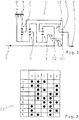
- Fig. 1 shows a transmission diagram 1 of a stepped automatic transmission, in which the inventive method for operating an automatic transmission is preferably used. So has the automatic transmission of the Fig. 1 via a total of four gear sets 2, 3, 4 and 5 to implement a present at a transmission input 6 transmission input torque in a transmission output torque at a transmission output 7.
- the gear sets 2, 3, 4 and 5 of the automatic transmission are according to Fig. 1 designed as planetary gear sets.
- the automatic transmission in addition to the four gear sets 2 to 5 further comprises a total of five switching elements 8, 9, 10, 11 and 12, wherein the switching element 8 as the switching element A, the switching element 9 as a switching element B, the switching element 10 as a switching element C, the switching element 11 is also referred to as switching element D and the switching element 12 as a switching element E.
- the switching element A and switching element B are each brakes
- the switching elements C, D and E are each clutches.
- the switching elements 8 to 12 are known per se switching elements of the Geretedsatzsystems.
- FIG. 1 schematically illustrated automatic transmission, which comprises the five switching elements 8 to 12, using the z.
- Fig. 2 eight forward gears and one reverse gear are realized, wherein in the left column of the circuit matrix 14, the eight forward gears "1" to “8” and the reverse gear “R” and in the upper row of the circuit matrix 14, the switching elements A to E are plotted , Switching elements marked with a dot in the switching element matrix 14 are closed in the respective gear. In each forward gear as well in reverse, therefore, three of the five switching elements are closed.
- the present invention now provides a method for operating such an automatic transmission in order to secure the same in a neutral position against an undesired frictional connection or momentary closure.
- At least one of the closed in each forward or reverse gear shift elements is completely open in the neutral position of the automatic transmission for securing the same before an undesirable adhesion.
- all three closed in the respective forward gear or reverse gear shift elements are fully opened in the neutral position to secure the automatic transmission in the neutral position.
- This first alternative of the first aspect of the present invention finds application especially when in the neutral position value is placed on safety against multiple errors when a hydraulic holding function, z. B. in case of an emergency in an emergency, would lead to the insertion of a driving position, or if this is due to the reasons of the transmission mechanism, z. B. because of internal speed conditions, is required.
- the first alternative of the first aspect of the present invention is used when the automatic transmission has been transferred from the forward gear "6" to the neutral position.
- This second alternative of the first aspect of the present invention is preferably used when in the neutral position to ensure safety against single errors, while sufficient reaction time at a subsequent gear insertion.
- the second alternative of the first aspect of the present invention applies when the automatic transmission from the forward gear “3" or from forward gear “4" or from forward gear “5" or from forward gear “7” or from forward gear “8” has been transferred to the neutral position.
- a first of the closed in each forward or reverse gear shift elements in the neutral position is completely opened to secure the automatic transmission in the neutral position, a second of the respective forward gear or reverse gear closed switching elements is partially filled in the neutral position so that no or almost no torque is transmitted from the second switching element, a third of the closed in each forward or reverse gear shift elements, however, is closed in the neutral position.
- a so-called air clearance of the same is overcome.
- This third alternative of the first aspect of the present invention is preferably used when in the neutral position sufficient safety against single errors is to be ensured, which means at least that a vehicle rolling is not possible, and at the same time a good reaction time should be present at a subsequent engagement ,
- the third alternative of the first aspect of the present invention is applied when the automatic transmission has been converted from the forward gear “1” or forward gear “2” or from the reverse gear “R” in the neutral position.
- the alternative (third alternative) which offers the best response time.
- the alternative becomes (second alternative), which places greater emphasis on safety, since then the reaction time is not so critical.
- two of the three closed in the forward or reverse gear shift elements are closed in the neutral position to secure the automatic transmission in the neutral position, whereas a third of the three closed in the respective forward gear or reverse switching elements fully open is.
- At least one further measure for securing the automatic transmission must be activated, such.
- Alternatively to or in combination with the above measures can be used as a further measure to additional security of the automatic transmission, an output speed monitoring in combination with a tilt monitoring of the motor vehicle.
- this second aspect of the invention only on an automatic transmission can be used, in which the torque transmission or power transmission in forward gear or reverse can be influenced by another located in the drive train switching element, wherein the further switching element can also be located within the transmission unit.
- this further switching element may be z. B. act to an external starting element.
- Such external starting element are z. B. in parallel hybrid systems, in which an electric motor and an internal combustion engine acts on an automatic transmission, upstream of the automatic transmission.
- the alternatives of the first aspect of the invention for driving the switching elements in the neutral position can be combined with this second aspect for driving the further switching element according to the second aspect of the invention.
- FIG. 1 and 2 the invention for the preferred application of an automatic transmission with five switching elements, of which three are closed in a forward gear and one reverse gear has been described, it should be noted at this point that the invention can also be used in automatic transmissions with a larger number of switching elements , even if each gear a larger number of switching elements is closed. In this case, the number of open or partially filled switching elements are transferred to these systems and kept the additional switching elements closed, so that then only the number of closed switching elements is different to the method described above.
- switching elements A to E or 8 to 12 which are controlled according to the first aspect of the invention, can also be referred to as internal gear or internal gear train system switching elements, whereas then the further located in the drive train switching element, which in the second aspect of the invention is of importance, may be referred to as gear external or as a gear train system external switching element.
Landscapes
- Engineering & Computer Science (AREA)
- General Engineering & Computer Science (AREA)
- Mechanical Engineering (AREA)
- Control Of Transmission Device (AREA)
Description
- Die Erfindung betrifft ein Verfahren zum Betreiben eines Automatgetriebes nach dem Oberbegriff des Anspruchs 1, wie aus der
EP 1 398 537 bzw. derUS 2004/053734 bekannt. - Fahrzeuge benötigen Getriebe, um Drehmomente und Drehzahlen zu wandeln. Aufgabe eines Fahrzeuggetriebes ist es, das Zugkraftangebot eines Antriebsaggregats umzusetzen. Die hier vorliegende Erfindung betrifft ein Verfahren zum Betreiben eines Automatgetriebes. Im Sinne der hier vorliegenden Erfindung sollen unter dem Begriff Automatgetriebe alle Getriebe mit einem automatischen Gangwechsel verstanden werden, die auch als Stufenautomatgetriebe bezeichnet werden.
- Bei der Entwicklung von Automatgetrieben ist ein Trend nach einer sich zunehmend vergrößernden Ganganzahl für insbesondere die Vorwärtsgänge eines Automatgetriebes feststellbar. So befinden sich derzeit Automatgetriebe mit acht Vorwärtsgängen in der Entwicklung, wobei solche Automatgetriebe mit acht Vorwärtsgängen über mindestens fünf Schaltelemente verfügen, und wobei zur Momentübertragung bzw. Kraftübertragung an einem solchen Automatgetriebe mindestens drei dieser mindestens fünf Schaltelemente in einem Vorwärtsgang sowie in einem Rückwärtsgang geschlossen sind. Befindet sich ein derartiges Automatgetriebe in Neutralposition, so muss dasselbe in der Neutralposition vor einem unerwünschten Momentschluss bzw. Kraftschluss gesichert werden, da ansonsten ein Kraftfahrzeug mit einem solchen Automatgetriebe sich ungewollt in Bewegung setzen könnte. Bislang sind jedoch keine Verfahren zum Betreiben solcher Automatgetriebe bekannt, die eine umfassende Absicherung der Automatgetriebe in der Neutralposition gewährleisten.
- Aus der
EP 1398537 A2 sind diverse Getriebeschemata für ein Automatgetriebe mit jeweils fünf Reibschaltelementen bekannt, von denen in jedem Gang drei geschlossen und zwei geöffnet sind. Dabei sind in kraftschlussfreier Neutralposition zwei der fünf Schaltelemente geschlossen, und zwar zwei derjenigen Schaltelemente, die sowohl im ersten Vorwärtsgang als auch im Rückwärtsgang geschlossen sind. - Die ein Verfahren zum Gangauslegen eines Automatgetriebes während der Fahrt betreffende
FR 2855583 A1 FR 2855583 A1 - Auch aus der
US 2004/0132576 A1 sind Automatgetriebe bekannt, bei denen in kraftschlussfreier Neutralposition alle Schaltelemente des Getriebes geöffnet sind, hier für ein 6-Gang-Doppelkupplungsgetriebe in Planetenbauweise, jeweils mit zwei Lamellenkupplungen, acht Klauen-Schalt-elementen und vier Planetenradsätzen, wobei in jedem Gang eine Lamellenkupplung und zwei Klauen-Schaltelemente in Eingriff sind. - Aus der
US 2004/053734 A1 sind 7-Gang-Automatgetriebe mit sechs Reibschaltelementen bekannt, von denen in jedem Gang drei geschlossen und drei offen sind. In Neutralposition des Getriebes hingegen ist nur eines der Reibschaltelemente geschlossen. - Hiervon ausgehend liegt der vorliegenden Erfindung das Problem zu Grunde, ein neuartiges Verfahren zum Betreiben eines Automatgetriebes zu schaffen.
- Nach einem ersten Aspekt der hier vorliegenden Erfindung wird dieses Problem durch ein Verfahren zum Betreiben eines Automatgetriebes gemäß Anspruch 1 gelöst. Hiernach ist in einer Neutralposition des Automatgetriebes zur Sicherung desselben vor einem nicht erwünschten Momentschluss bzw. Kraftschluss mindestens eines der im jeweiligen Vorwärtsgang bzw. Rückwärtsgang geschlossenen Schaltelemente vollständig geöffnet.
- Nach einem nicht beanspruchten zweiten Aspekt der hier vorliegenden Erfindung wird dieses Problem durch ein Verfahren zum Betreiben eines Automatgetriebes gelöst, bei dem in einer Neutralposition des Automatgetriebes zur Sicherung desselben vor einem nicht erwünschten Momentschluss bzw. Kraftschluss alle der im jeweiligen Vorwärtsgang bzw. Rückwärtsgang geschlossenen Schaltelemente geschlossen sind, wohingegen ein weiteres sich im Antriebsstrang befindliches Schaltelement, welches sich auch innerhalb der Getriebeeinheit befinden kann, vollständig geöffnet ist.
- Bevorzugte Weiterbildungen der Erfindung ergeben sich aus den Unteransprüchen und der nachfolgenden Beschreibung. Ausführungsbeispiele der Erfindung werden, ohne hierauf beschränkt zu sein, an Hand der Zeichnung näher erläutert. Dabei zeigt:
- Fig. 1
- ein Getriebeschema eines Automatgetriebes mit fünf Schaltelementen, bei welchem das erfindungsgemäße Verfahren vorteilhaft verwendbar ist;
- Fig. 2
- eine Schaltelementmatrix für die Schaltelemente des Getriebeschemas der
Fig. 1 zur Verdeutlichung welche Schaltelemente in welchem Gang geschlossen sind. - Die hier vorliegende Erfindung betrifft ein Verfahren zum Betreiben eines Automatgetriebes.
-
Fig. 1 zeigt ein Getriebeschema 1 eines Stufenautomatgetriebes, bei welchem das erfindungsgemäße Verfahren zum Betreiben eines Automatgetriebes bevorzugt Verwendung findet. So verfügt das Automatgetriebe derFig. 1 über insgesamt vier Getrieberadsätze 2, 3, 4 und 5 um ein an einem Getriebeeingang 6 anliegendes Getriebeeingangsmoment in ein Getriebeausgangsmoment an einem Getriebeausgang 7 umzusetzen. Die Getrieberadsätze 2, 3, 4 und 5 des Automatgetriebes sind dabei gemäßFig. 1 als Planetenrad-Getrieberadsätze ausgeführt. - Gemäß dem Getriebeschema 1 der
Fig. 1 verfügt das Automatgetriebe neben den vier Getrieberadsätzen 2 bis 5 weiterhin über insgesamt fünf Schaltelemente 8, 9, 10, 11 und 12, wobei das Schaltelement 8 auch als Schaltelement A, das Schaltelement 9 auch als Schaltelement B, das Schaltelement 10 auch als Schaltelement C, das Schaltelement 11 auch als Schaltelement D und das Schaltelement 12 auch als Schaltelement E bezeichnet wird. Bei dem Schaltelement A sowie Schaltelement B handelt es sich jeweils um Bremsen, bei den Schaltelementen C, D und E handelt es sich jeweils um Kupplungen. Die Schaltelemente 8 bis 12 sind an sich bekannte Schaltelemente des Getrieberadsatzsystems. - Für das in
Fig. 1 schematisiert dargestellte Automatgetriebe, welches die fünf Schaltelemente 8 bis 12 umfasst, können unter Verwendung der z. B. inFig. 2 dargestellten Schaltungsmatrix 14 acht Vorwärtsgänge sowie ein Rückwärtsgang realisiert werden, wobei in der linken Spalte der Schaltungsmatrix 14 die acht Vorwärtsgänge "1" bis "8" sowie der Rückwärtsgang "R" und in der oberen Zeile der Schaltungsmatrix 14 die Schaltelemente A bis E aufgetragen sind. Schaltelemente, die in der Schaltelementmatrix 14 mit einem Punkt markiert sind, sind im jeweiligen Gang geschlossen. In jedem Vorwärtsgang sowie im Rückwärtsgang sind demnach jeweils drei der fünf Schaltelemente geschlossen. - So sind z. B. für den Vorwärtsgang "1" die Schaltelemente A, B und C sowie für den Rückwärtsgang "R" die Schaltelemente A, B und D geschlossen. Die anderen Schaltelemente sind hingegen im jeweiligen Gang vollständig geöffnet.
- Zur Kraftübertragung bzw. Drehmomentübertragung vom Getriebeeingang 6 auf den Getriebeausgang 7 sind demnach bei dem in
Fig. 1 dargestellten Automatgetriebe in jedem Gang drei Schaltelemente vollständig geschlossen, zwei Schaltelemente sind hingegen vollständig geöffnet. - Die hier vorliegende Erfindung stellt nun ein Verfahren zum Betreiben eines solchen Automatgetriebes bereit, um dasselbe in einer Neutralposition vor einem unerwünschten Kraftschluss bzw. Momentschluss zu sichern.
- Nach einem ersten Aspekt der hier vorliegenden Erfindung ist in der Neutralposition des Automatgetriebes zur Sicherung desselben vor einem nicht erwünschten Kraftschluss mindestens eines der im jeweiligen Vorwärtsgang bzw. Rückwärtsgang geschlossenen Schaltelemente vollständig geöffnet. Dies kann dabei durch folgende vier Alternativen realisiert werden.
- Nach einer ersten Alternative des ersten Aspekts der hier vorliegenden Erfindung sind zur Sicherung des Automatgetriebes in der Neutralposition alle drei im jeweiligen Vorwärtsgang bzw. Rückwärtsgang geschlossenen Schaltelemente in der Neutralposition vollständig geöffnet.
- Diese erste Alternative des ersten Aspekts der hier vorliegenden Erfindung findet vor allem dann Anwendung, wenn in der Neutralposition Wert auf Sicherheit gegen Mehrfachfehler gelegt wird, wenn eine hydraulische Haltefunktion, z. B. bei Einfall in einen Notlauf, zum Einlegen einer Fahrposition führen würde, oder wenn dies aus Gründen der Getriebemechanik, z. B. wegen interner Drehzahlverhältnisse, erforderlich ist.
- Im gezeigten Ausführungsbeispiel findet die erste Alternative des ersten Aspekts der hier vorliegenden Erfindung dann Anwendung, wenn das Automatgetriebe ausgehend vom Vorwärtsgang "6" in die Neutralposition überführt worden ist.
- Nach einer zweiten Alternative des ersten Aspekts der hier vorliegenden Erfindung sind zur Sicherung des Automatgetriebes in der Neutralposition zwei der drei im jeweiligen Vorwärtsgang bzw. Rückwärtsgang geschlossenen Schaltelemente in der Neutralposition vollständig geöffnet, wohingegen ein drittes der drei im jeweiligen Vorwärtsgang bzw. Rückwärtsgang geschlossenen Schaltelemente in der Neutralposition geschlossen ist.
- Diese zweite Alternative des ersten Aspekts der hier vorliegenden Erfindung findet vorzugsweise dann Anwendung, wenn in der Neutralposition Sicherheit gegenüber Einfachfehlern gewährleistet werden soll, bei gleichzeitig ausreichender Reaktionszeit bei einem anschließenden Gangeinlegen.
- Im gezeigten Ausführungsbeispiel findet die zweite Alternative des ersten Aspekts der hier vorliegenden Erfindung dann Anwendung, wenn das Automatgetriebe ausgehend vom Vorwärtsgang "3" oder vom Vorwärtsgang "4" oder vom Vorwärtsgang "5" oder vom Vorwärtsgang "7" oder vom Vorwärtsgang "8" in die Neutralposition überführt worden ist.
- Nach einer dritten Alternative des ersten Aspekts der hier vorliegenden Erfindung ist zur Sicherung des Automatgetriebes in der Neutralposition ein erstes der im jeweiligen Vorwärtsgang bzw. Rückwärtsgang geschlossenen Schaltelemente in der Neutralposition vollständig geöffnet, ein zweites der im jeweiligen Vorwärtsgang bzw. Rückwärtsgang geschlossenen Schaltelemente ist in der Neutralposition derart teilbefüllt, dass kein oder annähernd kein Drehmoment von dem zweiten Schaltelement übertragen wird, ein drittes der im jeweiligen Vorwärtsgang bzw. Rückwärtsgang geschlossenen Schaltelemente ist hingegen in der Neutralposition geschlossen. Im teilbefüllten Zustand eines Schaltelements ist ein sogenanntes Luftspiel desselben überwunden.
- Diese dritte Alternative des ersten Aspekts der hier vorliegenden Erfindung findet vorzugsweise dann Verwendung, wenn in der Neutralposition ausreichend Sicherheit gegenüber Einfachfehlern gewährleistet werden soll, was zumindest bedeutet, dass ein Fahrzeuganrollen nicht möglich ist, und gleichzeitig eine gute Reaktionszeit bei einem anschließenden Gangeinlegen vorhanden sein soll.
- Im gezeigten Ausführungsbeispiel findet die dritte Alternative des ersten Aspekts der hier vorliegenden Erfindung dann Anwendung, wenn das Automatgetriebe ausgehend vom Vorwärtsgang "1" oder Vorwärtsgang "2" oder vom Rückwärtsgang "R" in die Neutralposition überführt worden ist.
- Die obigen drei Alternativen des ersten Aspekts der hier vorliegenden Erfindung bieten alle für sich genommen eine ausreichende Absicherung eines Automatgetriebes in der Neutralposition vor einem nicht erwünschten Kraftschluss bzw. Momentschluss und werden, wie oben ausgeführt, abhängig von den Gängen, von welchen das Automatgetriebe in die Neutralposition überführt worden ist, in Kombination miteinander zum Betreiben eines Automatgetriebes verwendet.
- So wird in den Neutralpositionen, von denen aus standardmäßig ein Gangeinlegen absolviert wird, die Alternative (dritte Alternative) gewählt, welche die beste Reaktionszeit bietet. Für die anderen Gänge, in welchen ein Gangeinlegen standardmäßig nur während der Fahrt vorgenommen wird, wird die Alternative (zweite Alternative) gewählt, die den größeren Schwerpunkt auf Sicherheit legt, da dann die Reaktionszeit nicht so kritisch ist.
- Sollten hydraulische bzw. getriebemechanische Gründe vorhanden sein, die es nicht erlauben, ein Schaltelement geschlossen zu halten, so wird die erste Alternative gewählt.
- Nach einer vierten Alternative des ersten Aspekts der hier vorliegenden Erfindung sind zur Sicherung des Automatgetriebes in der Neutralposition zwei der drei im jeweiligen Vorwärtsgang bzw. Rückwärtsgang geschlossenen Schaltelemente in der Neutralposition geschlossen, wohingegen ein drittes der drei im jeweiligen Vorwärtsgang bzw. Rückwärtsgang geschlossenen Schaltelemente vollständig geöffnet ist.
- Dann, wenn diese vierte Alternative des ersten Aspekts der Erfindung verwendet werden soll, muss mindestens eine weitere Maßnahme zur Sicherung des Automatgetriebes aktiviert werden, so z. B. eine Motordrehzahlbegrenzung und/oder eine Fahrzeugfeststellbremsbetätigung und/oder eine Fahrpedalbetätigungsbegrenzung. Alternativ zu den oder in Kombination mit den obigen Maßnahmen kann als weitere Maßnahme zur zusätzlichen Sicherung des Automatgetriebes eine Abtriebsdrehzahlüberwachung in Kombination mit einer Neigungsüberwachung des Kraftfahrzeugs verwendet werden.
- Nach einem zweiten Aspekt der hier vorliegenden Erfindung sind zur Sicherung eines Automatgetriebes in der Neutralposition vor einem nicht erwünschten Momentfluss bzw. Kraftfluss alle drei im jeweiligen Vorwärtsgang bzw. Rückwärtsgang geschlossenen Schaltelemente auch in der Neutralposition geschlossen, wobei dieser zweite Aspekt der Erfindung nur an einem Automatgetriebe verwendet werden kann, bei welchem die Momentübertragung bzw. Kraftübertragung im Vorwärtsgang bzw. Rückwärtsgang über ein weiteres sich im Antriebsstrang befindliches Schaltelement beeinflusst werden kann, wobei sich das weitere Schaltelement auch innerhalb der Getriebeeinheit befinden kann.
- Bei diesem weiteren Schaltelement kann es sich z. B. um ein externes Anfahrelement handeln. Derartige externe Anfahrelement sind z. B. bei Parallelhybridsystemen, bei welchen ein Elektromotor und ein Verbrennungsmotor auf ein Automatgetriebe wirkt, dem Automatgetriebe vorgeschaltet. Die Alternativen des ersten Aspekts der Erfindung zur Ansteuerung der Schaltelemente in der Neutralposition sind mit diesem zweiten Aspekt zur Ansteuerung des weiteren Schaltelements nach dem zweiten Aspekt der Erfindung kombinierbar.
- Obwohl unter Bezugnahme auf
Fig. 1 und 2 die Erfindung für den bevorzugten Anwendungsfall eines Automatgetriebes mit fünf Schaltelementen, von welchen jeweils drei in einem Vorwärtsgang und einem Rückwärtsgang geschlossen sind, beschrieben wurde, sei an dieser Stelle darauf hingewiesen, dass die Erfindung auch bei Automatgetrieben mit einer größeren Anzahl von Schaltelementen verwendet werden kann, und zwar auch dann, wenn pro Gang eine größere Anzahl an Schaltelementen geschlossen ist. Für diesen Fall werden die Anzahl der offenen bzw. teilbefüllten Schaltelemente auf diese Systeme übertragen und die zusätzlichen Schaltelemente geschlossen gehalten, sodass zu dem oben beschriebenen Verfahren dann nur die Anzahl der geschlossenen Schaltelemente unterschiedlich ist. - Abschließend sei darauf hingewiesen, dass die Schaltelemente A bis E bzw. 8 bis 12, die nach dem ersten Aspekt der Erfindung angesteuert werden, auch als getriebeinterne bzw. als getrieberadsatzsysteminterne Schaltelemente bezeichnet werden können, wohingegen dann das weitere sich im Antriebsstrang befindliche Schaltelement, welches beim zweiten Aspekt der Erfindung von Bedeutung ist, als getriebeexternes bzw. als getrieberadsatzsystemexternes Schaltelement bezeichnet werden kann.
-
- 1
- Getriebeschema
- 2
- Getrieberadsatz
- 3
- Getrieberadsatz
- 4
- Getrieberadsatz
- 5
- Getrieberadsatz
- 6
- Getriebeeingang
- 7
- Getriebeausgang
- 8
- Schaltelement A
- 9
- Schaltelement B
- 10
- Schaltelement C
- 11
- Schaltelement D
- 12
- Schaltelement E
- 14
- Schaltelementmatrix
Claims (2)
- Verfahren zum Betreiben eines Automatgetriebes eines Kraftfahrzeugs, insbesondere eines Stufenautomatgetriebes, wobei das Automatgetriebe mindestens fünf Schaltelemente aufweist, wobei zur Drehmomentübertragung bzw. Kraftübertragung in jedem Vorwärts- und Rückwärtsgang mindestens drei Schaltelemente geschlossen sind, und wobei in einer Neutralposition des Automatgetriebes zur Sicherung desselben vor einem nicht erwünschten Drehmomentschluss bzw. Kraftschluss mindestens eines der im jeweiligen Vorwärtsgang bzw. Rückwärtsgang geschlossenen Schaltelemente vollständig geöffnet ist, dadurch gekennzeichnet, dass in der Neutralposition des Automatgetriebes ein erstes der im jeweiligen Vorwärtsgang bzw. Rückwärtsgang geschlossenen Schaltelemente vollständig geöffnet ist, ein zweites der im jeweiligen Vorwärtsgang bzw. Rückwärtsgang geschlossenen Schaltelemente derart teilbefüllt ist, dass von demselben kein oder annähend kein Drehmoment übertragen wird, und ein drittes der im jeweiligen Vorwärtsgang bzw. Rückwärtsgang geschlossenen Schaltelemente geschlossen ist.
- Verfahren nach Anspruch 1, dadurch gekennzeichnet, dass das Automatgetriebe genau fünf Schaltelemente aufweist, von denen zur Drehmomentübertragung bzw. Kraftübertragung in jedem Vorwärts- und Rückwärtsgang drei Schaltelemente geschlossen sind.
Applications Claiming Priority (2)
| Application Number | Priority Date | Filing Date | Title |
|---|---|---|---|
| DE102006014947A DE102006014947A1 (de) | 2006-03-31 | 2006-03-31 | Verfahren zum Betreiben eines Automatgetriebes |
| PCT/EP2007/051834 WO2007113059A1 (de) | 2006-03-31 | 2007-02-27 | Verfahren zum betreiben eines automatgetriebes |
Publications (2)
| Publication Number | Publication Date |
|---|---|
| EP2002156A1 EP2002156A1 (de) | 2008-12-17 |
| EP2002156B1 true EP2002156B1 (de) | 2018-07-25 |
Family
ID=38110029
Family Applications (1)
| Application Number | Title | Priority Date | Filing Date |
|---|---|---|---|
| EP07712326.3A Active EP2002156B1 (de) | 2006-03-31 | 2007-02-27 | Verfahren zum betreiben eines automatgetriebes |
Country Status (4)
| Country | Link |
|---|---|
| US (1) | US8162796B2 (de) |
| EP (1) | EP2002156B1 (de) |
| DE (1) | DE102006014947A1 (de) |
| WO (1) | WO2007113059A1 (de) |
Families Citing this family (11)
| Publication number | Priority date | Publication date | Assignee | Title |
|---|---|---|---|---|
| DE102007001496B4 (de) | 2007-01-10 | 2020-01-16 | Zf Friedrichshafen Ag | Kraftfahrzeug-Getriebe und Verfahren zur Überwachung von Kraftschluss in demselben bei vorgegebener Neutral- und/oder Parkposition |
| US7699741B2 (en) * | 2007-01-25 | 2010-04-20 | Gm Global Technology Operations, Inc. | Multi-speed transmission |
| DE102007000561B4 (de) * | 2007-10-24 | 2022-09-01 | Zf Friedrichshafen Ag | Elektrohydraulische Steuervorrichtung einer Getriebeeinrichtung |
| DE102007050802B4 (de) | 2007-10-24 | 2023-07-13 | Zf Friedrichshafen Ag | Elektrohydraulische Getriebesteuerung, Getriebeeinrichtung und Fahrzeugantriebsstrang |
| DE102009045508A1 (de) * | 2009-10-09 | 2011-04-14 | Zf Friedrichshafen Ag | Getriebevorrichtung und Verfahren zum Betreiben einer Getriebevorrichtung |
| US9039564B2 (en) | 2012-06-22 | 2015-05-26 | Gm Global Technology Operations, Llc | Multi-speed transmission |
| US9528601B2 (en) | 2014-07-01 | 2016-12-27 | GL Global Technology Operations LLC | Automatic transmission power flow detection |
| US9625007B2 (en) * | 2014-08-12 | 2017-04-18 | Allison Transmission, Inc. | Multi-speed transmission |
| US10023190B2 (en) * | 2016-10-28 | 2018-07-17 | Ford Global Technologies, Llc | Method and control for operating a transmission in neutral |
| US10295053B2 (en) | 2016-10-28 | 2019-05-21 | Ford Global Technologies, Llc | Method and control for operating transmission during clutch failure |
| JP6440762B2 (ja) * | 2017-03-27 | 2018-12-19 | 本田技研工業株式会社 | 自動変速機 |
Citations (1)
| Publication number | Priority date | Publication date | Assignee | Title |
|---|---|---|---|---|
| EP1398537A2 (de) * | 2002-09-13 | 2004-03-17 | General Motors Corporation | Mehrgängige Getriebefamilie mit zwei Eingangskupplungen |
Family Cites Families (26)
| Publication number | Priority date | Publication date | Assignee | Title |
|---|---|---|---|---|
| FR2656055B1 (fr) * | 1989-12-18 | 1994-04-29 | Lepelletier Pierre | Transmission automatique multivitesses pour vehicule automobile. |
| US5134903A (en) | 1990-06-30 | 1992-08-04 | Suzuki Motor Corporation | Shift control device of transmission |
| JPH0565957A (ja) * | 1991-09-04 | 1993-03-19 | Nissan Motor Co Ltd | 自動変速機の変速制御装置 |
| US5251509A (en) | 1992-04-03 | 1993-10-12 | General Motors Corporation | Adaptive pressure control for an automatic transmission |
| JPH0640272A (ja) * | 1992-07-22 | 1994-02-15 | Jatco Corp | エンジン・自動変速機の制御装置 |
| DE4334172C2 (de) | 1992-10-24 | 1997-07-03 | Volkswagen Ag | Verfahren zur Steuerung und Regelung des Hochschaltvorganges in einem automatischen Getriebe |
| JP3614928B2 (ja) | 1995-04-05 | 2005-01-26 | 本田技研工業株式会社 | 自動変速機の変速制御装置 |
| JP3377349B2 (ja) | 1995-11-29 | 2003-02-17 | ジヤトコ株式会社 | 自動変速機のダウンシフト制御装置 |
| JP3470508B2 (ja) | 1996-05-29 | 2003-11-25 | トヨタ自動車株式会社 | 自動変速機の変速制御装置 |
| JPH1019116A (ja) * | 1996-07-03 | 1998-01-23 | Toyota Motor Corp | 車両用自動変速機の制御装置 |
| DE19725513A1 (de) | 1997-06-17 | 1998-12-24 | Zahnradfabrik Friedrichshafen | Verfahren zur Verminderung des Schaltrucks beim Gangauslegen |
| DE19750447A1 (de) * | 1997-11-14 | 1999-06-02 | Zahnradfabrik Friedrichshafen | Verfahren zum Steuern eines Automatgetriebes |
| DE10043510A1 (de) | 2000-09-01 | 2002-03-14 | Peter Tenberge | Stufenloses Automatikgetriebe für Fahrzeuge |
| US6502476B2 (en) * | 2000-12-13 | 2003-01-07 | Eaton Corporation | Transmission system utilizing centrifugal clutch |
| US6767306B2 (en) * | 2002-09-12 | 2004-07-27 | General Motors Corporation | Transmission mechanisms with three gear sets and a stationary gear member |
| US6743147B2 (en) * | 2002-10-30 | 2004-06-01 | General Motors Corporation | Family of multi-speed planetary transmissions having a clutched input and one stationary member |
| US6764424B1 (en) | 2003-01-03 | 2004-07-20 | General Motors Corporation | Six-speed dual-clutch transmissions having planetary gear sets with three interconnecting members |
| DE10320775A1 (de) * | 2003-05-09 | 2004-12-02 | Zf Friedrichshafen Ag | Verfahren zum Steuern eines Automatgetriebes mit einer Anfahrkupplung und mehreren Schaltelementen |
| JP3855966B2 (ja) | 2003-05-28 | 2006-12-13 | トヨタ自動車株式会社 | 車両用自動変速機のニュートラル制御装置 |
| JP4179078B2 (ja) | 2003-07-22 | 2008-11-12 | トヨタ自動車株式会社 | 車両の発進制御装置 |
| JP4146306B2 (ja) | 2003-07-28 | 2008-09-10 | トヨタ自動車株式会社 | 自動変速機の変速制御装置 |
| MY149206A (en) * | 2004-08-20 | 2013-07-31 | Drivetrain Systems Internat Pty Ltd | Transmission |
| DE102004040642B4 (de) * | 2004-08-21 | 2015-11-26 | Zf Friedrichshafen Ag | Mehrstufengetriebe |
| DE102004040613A1 (de) * | 2004-08-21 | 2006-03-09 | Zf Friedrichshafen Ag | Mehrstufengetriebe |
| DE102005005617A1 (de) * | 2004-08-21 | 2006-03-09 | Zf Friedrichshafen Ag | Mehrstufengetriebe |
| US7150696B2 (en) * | 2004-08-24 | 2006-12-19 | General Motors Corporation | Planetary transmissions having a stationary gear member and clutched input members |
-
2006
- 2006-03-31 DE DE102006014947A patent/DE102006014947A1/de not_active Withdrawn
-
2007
- 2007-02-27 EP EP07712326.3A patent/EP2002156B1/de active Active
- 2007-02-27 WO PCT/EP2007/051834 patent/WO2007113059A1/de not_active Ceased
- 2007-02-27 US US12/225,620 patent/US8162796B2/en active Active
Patent Citations (1)
| Publication number | Priority date | Publication date | Assignee | Title |
|---|---|---|---|---|
| EP1398537A2 (de) * | 2002-09-13 | 2004-03-17 | General Motors Corporation | Mehrgängige Getriebefamilie mit zwei Eingangskupplungen |
Also Published As
| Publication number | Publication date |
|---|---|
| EP2002156A1 (de) | 2008-12-17 |
| WO2007113059A1 (de) | 2007-10-11 |
| US8162796B2 (en) | 2012-04-24 |
| DE102006014947A1 (de) | 2007-10-04 |
| US20090176612A1 (en) | 2009-07-09 |
Similar Documents
| Publication | Publication Date | Title |
|---|---|---|
| EP2002156B1 (de) | Verfahren zum betreiben eines automatgetriebes | |
| EP2002157B1 (de) | Verfahren zum betreiben eines automatgetriebes | |
| DE102020210677B4 (de) | Automatisierte Getriebeanordnung sowie Antriebsstranganordnung mit einer solchen automatisierten Getriebeanordnung | |
| EP2652364B1 (de) | Verfahren zum betreiben einer getriebevorrichtung eines fahrzeugantriebsstranges bei vorliegen einer anforderung für einen übersetzungswechsel | |
| EP1507092B1 (de) | Verfahren zur Steuerung eines Doppelkupplungsgetriebes | |
| EP2013516B1 (de) | Verfahren zum betreiben eines automatgetriebes | |
| DE102010000859A1 (de) | Verfahren zum Betreiben einer Getriebevorrichtung mit mehreren reibschlüssigen Schaltelementen und wenigstens einem formschlüssigen Schaltelement | |
| DE102012212370A1 (de) | Schaltgetriebe eines Kraftfahrzeugs | |
| DE102013200646A1 (de) | Verfahren zum Schalten eines in Gruppenbauweise ausgeführten Kraftfahrzeug-getriebes, sowie Kraftfahrzeuggetriebe in Gruppenbauweise | |
| WO1988003097A1 (fr) | Systeme de transmission pour vehicules a moteur | |
| EP3154836B1 (de) | Verfahren zum betreiben einer getriebeeinrichtung für ein kraftfahrzeug sowie entsprechende getriebeeinrichtung | |
| DE102017117079A1 (de) | Kraftfahrzeug-Immobilisierungsverfahren und Doppelkupplungsgetriebe | |
| DE102009002595A1 (de) | Dämpfungsanordnung | |
| DE102011054337A1 (de) | Betätigungsvorrichtung für ein automatisiertes Doppelkupplungsgetriebe eines Kraftfahrzeuges sowie Verfahren zur Steuerung einer derartigen Betätigungsvorrichtung | |
| DE102018111512A1 (de) | Getriebe mit abschwächung der kaltschaltverzögerung | |
| EP2137038A1 (de) | Verfahren zum betreiben eines antriebsstrangs | |
| DE102010063026B4 (de) | Verfahren zum Betreiben einer Getriebevorrichtung eines Fahrzeugantriebsstranges | |
| WO2022058122A1 (de) | Kraftfahrzeug mit mindestens zwei antriebsmotoren und mit einem automatikgetriebe, das eine feste und eine leistungsverzweigte übersetzungsstufe aufweist | |
| DE102019209220A1 (de) | Verfahren zum Betreiben eines Getriebes | |
| DE102023211908A1 (de) | Verfahren zum Betreiben eines Kraftfahrzeuggetriebes | |
| EP2979009B1 (de) | Verfahren zum schalten eines getriebes | |
| DE102023201903A1 (de) | Verfahren zur Steuerung der Schaltungen der Gangstufen eines Automatikgetriebes eines Kraftfahrzeuges | |
| DE102017200417A1 (de) | Verfahren und Steuergerät zum Betreiben eines Kraftfahrzeugs | |
| DE102006038755B3 (de) | Getriebeeinrichtung für ein Kraftfahrzeug | |
| DE10327444A1 (de) | Verfahren zum Betrieb eines Antriebsstrangs eines Kraftfahrzeugs |
Legal Events
| Date | Code | Title | Description |
|---|---|---|---|
| PUAI | Public reference made under article 153(3) epc to a published international application that has entered the european phase |
Free format text: ORIGINAL CODE: 0009012 |
|
| 17P | Request for examination filed |
Effective date: 20080805 |
|
| AK | Designated contracting states |
Kind code of ref document: A1 Designated state(s): AT BE BG CH CY CZ DE DK EE ES FI FR GB GR HU IE IS IT LI LT LU LV MC NL PL PT RO SE SI SK TR |
|
| 17Q | First examination report despatched |
Effective date: 20120411 |
|
| 17Q | First examination report despatched |
Effective date: 20120612 |
|
| DAX | Request for extension of the european patent (deleted) | ||
| REG | Reference to a national code |
Ref country code: DE Ref legal event code: R079 Ref document number: 502007016300 Country of ref document: DE Free format text: PREVIOUS MAIN CLASS: F16H0061200000 Ipc: F16H0061040000 |
|
| GRAP | Despatch of communication of intention to grant a patent |
Free format text: ORIGINAL CODE: EPIDOSNIGR1 |
|
| STAA | Information on the status of an ep patent application or granted ep patent |
Free format text: STATUS: GRANT OF PATENT IS INTENDED |
|
| RIC1 | Information provided on ipc code assigned before grant |
Ipc: F16H 61/12 20100101ALI20180123BHEP Ipc: F16H 61/20 20060101ALI20180123BHEP Ipc: F16H 61/04 20060101AFI20180123BHEP |
|
| INTG | Intention to grant announced |
Effective date: 20180228 |
|
| GRAS | Grant fee paid |
Free format text: ORIGINAL CODE: EPIDOSNIGR3 |
|
| GRAA | (expected) grant |
Free format text: ORIGINAL CODE: 0009210 |
|
| STAA | Information on the status of an ep patent application or granted ep patent |
Free format text: STATUS: THE PATENT HAS BEEN GRANTED |
|
| AK | Designated contracting states |
Kind code of ref document: B1 Designated state(s): AT BE BG CH CY CZ DE DK EE ES FI FR GB GR HU IE IS IT LI LT LU LV MC NL PL PT RO SE SI SK TR |
|
| REG | Reference to a national code |
Ref country code: GB Ref legal event code: FG4D Free format text: NOT ENGLISH |
|
| REG | Reference to a national code |
Ref country code: CH Ref legal event code: EP |
|
| REG | Reference to a national code |
Ref country code: AT Ref legal event code: REF Ref document number: 1022122 Country of ref document: AT Kind code of ref document: T Effective date: 20180815 |
|
| REG | Reference to a national code |
Ref country code: DE Ref legal event code: R096 Ref document number: 502007016300 Country of ref document: DE |
|
| REG | Reference to a national code |
Ref country code: IE Ref legal event code: FG4D Free format text: LANGUAGE OF EP DOCUMENT: GERMAN |
|
| REG | Reference to a national code |
Ref country code: NL Ref legal event code: MP Effective date: 20180725 |
|
| REG | Reference to a national code |
Ref country code: LT Ref legal event code: MG4D |
|
| PG25 | Lapsed in a contracting state [announced via postgrant information from national office to epo] |
Ref country code: NL Free format text: LAPSE BECAUSE OF FAILURE TO SUBMIT A TRANSLATION OF THE DESCRIPTION OR TO PAY THE FEE WITHIN THE PRESCRIBED TIME-LIMIT Effective date: 20180725 |
|
| PG25 | Lapsed in a contracting state [announced via postgrant information from national office to epo] |
Ref country code: SE Free format text: LAPSE BECAUSE OF FAILURE TO SUBMIT A TRANSLATION OF THE DESCRIPTION OR TO PAY THE FEE WITHIN THE PRESCRIBED TIME-LIMIT Effective date: 20180725 Ref country code: BG Free format text: LAPSE BECAUSE OF FAILURE TO SUBMIT A TRANSLATION OF THE DESCRIPTION OR TO PAY THE FEE WITHIN THE PRESCRIBED TIME-LIMIT Effective date: 20181025 Ref country code: IS Free format text: LAPSE BECAUSE OF FAILURE TO SUBMIT A TRANSLATION OF THE DESCRIPTION OR TO PAY THE FEE WITHIN THE PRESCRIBED TIME-LIMIT Effective date: 20181125 Ref country code: PL Free format text: LAPSE BECAUSE OF FAILURE TO SUBMIT A TRANSLATION OF THE DESCRIPTION OR TO PAY THE FEE WITHIN THE PRESCRIBED TIME-LIMIT Effective date: 20180725 Ref country code: LT Free format text: LAPSE BECAUSE OF FAILURE TO SUBMIT A TRANSLATION OF THE DESCRIPTION OR TO PAY THE FEE WITHIN THE PRESCRIBED TIME-LIMIT Effective date: 20180725 Ref country code: GR Free format text: LAPSE BECAUSE OF FAILURE TO SUBMIT A TRANSLATION OF THE DESCRIPTION OR TO PAY THE FEE WITHIN THE PRESCRIBED TIME-LIMIT Effective date: 20181026 Ref country code: FI Free format text: LAPSE BECAUSE OF FAILURE TO SUBMIT A TRANSLATION OF THE DESCRIPTION OR TO PAY THE FEE WITHIN THE PRESCRIBED TIME-LIMIT Effective date: 20180725 |
|
| PG25 | Lapsed in a contracting state [announced via postgrant information from national office to epo] |
Ref country code: LV Free format text: LAPSE BECAUSE OF FAILURE TO SUBMIT A TRANSLATION OF THE DESCRIPTION OR TO PAY THE FEE WITHIN THE PRESCRIBED TIME-LIMIT Effective date: 20180725 Ref country code: ES Free format text: LAPSE BECAUSE OF FAILURE TO SUBMIT A TRANSLATION OF THE DESCRIPTION OR TO PAY THE FEE WITHIN THE PRESCRIBED TIME-LIMIT Effective date: 20180725 |
|
| REG | Reference to a national code |
Ref country code: DE Ref legal event code: R097 Ref document number: 502007016300 Country of ref document: DE |
|
| PG25 | Lapsed in a contracting state [announced via postgrant information from national office to epo] |
Ref country code: RO Free format text: LAPSE BECAUSE OF FAILURE TO SUBMIT A TRANSLATION OF THE DESCRIPTION OR TO PAY THE FEE WITHIN THE PRESCRIBED TIME-LIMIT Effective date: 20180725 Ref country code: EE Free format text: LAPSE BECAUSE OF FAILURE TO SUBMIT A TRANSLATION OF THE DESCRIPTION OR TO PAY THE FEE WITHIN THE PRESCRIBED TIME-LIMIT Effective date: 20180725 Ref country code: IT Free format text: LAPSE BECAUSE OF FAILURE TO SUBMIT A TRANSLATION OF THE DESCRIPTION OR TO PAY THE FEE WITHIN THE PRESCRIBED TIME-LIMIT Effective date: 20180725 Ref country code: CZ Free format text: LAPSE BECAUSE OF FAILURE TO SUBMIT A TRANSLATION OF THE DESCRIPTION OR TO PAY THE FEE WITHIN THE PRESCRIBED TIME-LIMIT Effective date: 20180725 |
|
| PG25 | Lapsed in a contracting state [announced via postgrant information from national office to epo] |
Ref country code: SK Free format text: LAPSE BECAUSE OF FAILURE TO SUBMIT A TRANSLATION OF THE DESCRIPTION OR TO PAY THE FEE WITHIN THE PRESCRIBED TIME-LIMIT Effective date: 20180725 Ref country code: DK Free format text: LAPSE BECAUSE OF FAILURE TO SUBMIT A TRANSLATION OF THE DESCRIPTION OR TO PAY THE FEE WITHIN THE PRESCRIBED TIME-LIMIT Effective date: 20180725 |
|
| PLBE | No opposition filed within time limit |
Free format text: ORIGINAL CODE: 0009261 |
|
| STAA | Information on the status of an ep patent application or granted ep patent |
Free format text: STATUS: NO OPPOSITION FILED WITHIN TIME LIMIT |
|
| 26N | No opposition filed |
Effective date: 20190426 |
|
| PG25 | Lapsed in a contracting state [announced via postgrant information from national office to epo] |
Ref country code: SI Free format text: LAPSE BECAUSE OF FAILURE TO SUBMIT A TRANSLATION OF THE DESCRIPTION OR TO PAY THE FEE WITHIN THE PRESCRIBED TIME-LIMIT Effective date: 20180725 |
|
| REG | Reference to a national code |
Ref country code: CH Ref legal event code: PL |
|
| GBPC | Gb: european patent ceased through non-payment of renewal fee |
Effective date: 20190227 |
|
| PG25 | Lapsed in a contracting state [announced via postgrant information from national office to epo] |
Ref country code: LU Free format text: LAPSE BECAUSE OF NON-PAYMENT OF DUE FEES Effective date: 20190227 Ref country code: MC Free format text: LAPSE BECAUSE OF FAILURE TO SUBMIT A TRANSLATION OF THE DESCRIPTION OR TO PAY THE FEE WITHIN THE PRESCRIBED TIME-LIMIT Effective date: 20180725 |
|
| REG | Reference to a national code |
Ref country code: BE Ref legal event code: MM Effective date: 20190228 |
|
| REG | Reference to a national code |
Ref country code: IE Ref legal event code: MM4A |
|
| PG25 | Lapsed in a contracting state [announced via postgrant information from national office to epo] |
Ref country code: LI Free format text: LAPSE BECAUSE OF NON-PAYMENT OF DUE FEES Effective date: 20190228 Ref country code: CH Free format text: LAPSE BECAUSE OF NON-PAYMENT OF DUE FEES Effective date: 20190228 |
|
| PG25 | Lapsed in a contracting state [announced via postgrant information from national office to epo] |
Ref country code: GB Free format text: LAPSE BECAUSE OF NON-PAYMENT OF DUE FEES Effective date: 20190227 Ref country code: IE Free format text: LAPSE BECAUSE OF NON-PAYMENT OF DUE FEES Effective date: 20190227 |
|
| PG25 | Lapsed in a contracting state [announced via postgrant information from national office to epo] |
Ref country code: FR Free format text: LAPSE BECAUSE OF NON-PAYMENT OF DUE FEES Effective date: 20190228 Ref country code: BE Free format text: LAPSE BECAUSE OF NON-PAYMENT OF DUE FEES Effective date: 20190228 |
|
| PG25 | Lapsed in a contracting state [announced via postgrant information from national office to epo] |
Ref country code: TR Free format text: LAPSE BECAUSE OF FAILURE TO SUBMIT A TRANSLATION OF THE DESCRIPTION OR TO PAY THE FEE WITHIN THE PRESCRIBED TIME-LIMIT Effective date: 20180725 |
|
| REG | Reference to a national code |
Ref country code: AT Ref legal event code: MM01 Ref document number: 1022122 Country of ref document: AT Kind code of ref document: T Effective date: 20190227 |
|
| PG25 | Lapsed in a contracting state [announced via postgrant information from national office to epo] |
Ref country code: AT Free format text: LAPSE BECAUSE OF NON-PAYMENT OF DUE FEES Effective date: 20190227 |
|
| PG25 | Lapsed in a contracting state [announced via postgrant information from national office to epo] |
Ref country code: PT Free format text: LAPSE BECAUSE OF FAILURE TO SUBMIT A TRANSLATION OF THE DESCRIPTION OR TO PAY THE FEE WITHIN THE PRESCRIBED TIME-LIMIT Effective date: 20181125 |
|
| PG25 | Lapsed in a contracting state [announced via postgrant information from national office to epo] |
Ref country code: CY Free format text: LAPSE BECAUSE OF FAILURE TO SUBMIT A TRANSLATION OF THE DESCRIPTION OR TO PAY THE FEE WITHIN THE PRESCRIBED TIME-LIMIT Effective date: 20180725 |
|
| PG25 | Lapsed in a contracting state [announced via postgrant information from national office to epo] |
Ref country code: HU Free format text: LAPSE BECAUSE OF FAILURE TO SUBMIT A TRANSLATION OF THE DESCRIPTION OR TO PAY THE FEE WITHIN THE PRESCRIBED TIME-LIMIT; INVALID AB INITIO Effective date: 20070227 |
|
| P01 | Opt-out of the competence of the unified patent court (upc) registered |
Effective date: 20230528 |
|
| PGFP | Annual fee paid to national office [announced via postgrant information from national office to epo] |
Ref country code: DE Payment date: 20260102 Year of fee payment: 20 |