EP2002126B1 - Rotary pump with coaxial magnetic coupling - Google Patents
Rotary pump with coaxial magnetic coupling Download PDFInfo
- Publication number
- EP2002126B1 EP2002126B1 EP07723756A EP07723756A EP2002126B1 EP 2002126 B1 EP2002126 B1 EP 2002126B1 EP 07723756 A EP07723756 A EP 07723756A EP 07723756 A EP07723756 A EP 07723756A EP 2002126 B1 EP2002126 B1 EP 2002126B1
- Authority
- EP
- European Patent Office
- Prior art keywords
- pump
- pump according
- impeller
- rotary pump
- magnetic
- Prior art date
- Legal status (The legal status is an assumption and is not a legal conclusion. Google has not performed a legal analysis and makes no representation as to the accuracy of the status listed.)
- Not-in-force
Links
- 238000010168 coupling process Methods 0.000 title claims abstract description 20
- 238000005859 coupling reaction Methods 0.000 title claims abstract description 20
- 230000008878 coupling Effects 0.000 title claims abstract description 19
- 230000005291 magnetic effect Effects 0.000 title claims description 69
- 239000007788 liquid Substances 0.000 claims abstract description 32
- 230000003068 static effect Effects 0.000 claims abstract description 3
- 239000000463 material Substances 0.000 claims description 18
- 238000001816 cooling Methods 0.000 claims description 11
- 238000000465 moulding Methods 0.000 claims description 7
- 230000001681 protective effect Effects 0.000 claims description 6
- 239000012530 fluid Substances 0.000 claims description 5
- 239000004605 External Lubricant Substances 0.000 claims description 2
- 230000002093 peripheral effect Effects 0.000 claims description 2
- 230000015572 biosynthetic process Effects 0.000 claims 1
- 238000007789 sealing Methods 0.000 claims 1
- 230000003019 stabilising effect Effects 0.000 claims 1
- 238000005096 rolling process Methods 0.000 abstract description 7
- 230000005540 biological transmission Effects 0.000 abstract description 2
- 238000000638 solvent extraction Methods 0.000 abstract 1
- 238000010276 construction Methods 0.000 description 14
- 238000013461 design Methods 0.000 description 12
- 230000008901 benefit Effects 0.000 description 11
- 238000005461 lubrication Methods 0.000 description 8
- 230000007257 malfunction Effects 0.000 description 5
- 230000009471 action Effects 0.000 description 4
- 238000012544 monitoring process Methods 0.000 description 4
- 230000001050 lubricating effect Effects 0.000 description 3
- 239000004033 plastic Substances 0.000 description 3
- WZZBNLYBHUDSHF-DHLKQENFSA-N 1-[(3s,4s)-4-[8-(2-chloro-4-pyrimidin-2-yloxyphenyl)-7-fluoro-2-methylimidazo[4,5-c]quinolin-1-yl]-3-fluoropiperidin-1-yl]-2-hydroxyethanone Chemical compound CC1=NC2=CN=C3C=C(F)C(C=4C(=CC(OC=5N=CC=CN=5)=CC=4)Cl)=CC3=C2N1[C@H]1CCN(C(=O)CO)C[C@@H]1F WZZBNLYBHUDSHF-DHLKQENFSA-N 0.000 description 2
- 206010041235 Snoring Diseases 0.000 description 2
- 230000006378 damage Effects 0.000 description 2
- 230000002349 favourable effect Effects 0.000 description 2
- 230000005294 ferromagnetic effect Effects 0.000 description 2
- 238000005192 partition Methods 0.000 description 2
- 230000002829 reductive effect Effects 0.000 description 2
- 230000003716 rejuvenation Effects 0.000 description 2
- 230000001953 sensory effect Effects 0.000 description 2
- 238000007493 shaping process Methods 0.000 description 2
- KQZLRWGGWXJPOS-NLFPWZOASA-N 1-[(1R)-1-(2,4-dichlorophenyl)ethyl]-6-[(4S,5R)-4-[(2S)-2-(hydroxymethyl)pyrrolidin-1-yl]-5-methylcyclohexen-1-yl]pyrazolo[3,4-b]pyrazine-3-carbonitrile Chemical compound ClC1=C(C=CC(=C1)Cl)[C@@H](C)N1N=C(C=2C1=NC(=CN=2)C1=CC[C@@H]([C@@H](C1)C)N1[C@@H](CCC1)CO)C#N KQZLRWGGWXJPOS-NLFPWZOASA-N 0.000 description 1
- 238000005299 abrasion Methods 0.000 description 1
- 230000002411 adverse Effects 0.000 description 1
- 238000013459 approach Methods 0.000 description 1
- 230000004323 axial length Effects 0.000 description 1
- 230000015556 catabolic process Effects 0.000 description 1
- 229940125877 compound 31 Drugs 0.000 description 1
- 150000001875 compounds Chemical class 0.000 description 1
- 230000007797 corrosion Effects 0.000 description 1
- 238000005260 corrosion Methods 0.000 description 1
- 230000002950 deficient Effects 0.000 description 1
- 208000001848 dysentery Diseases 0.000 description 1
- 230000000694 effects Effects 0.000 description 1
- 230000001747 exhibiting effect Effects 0.000 description 1
- 238000011010 flushing procedure Methods 0.000 description 1
- 230000012447 hatching Effects 0.000 description 1
- 231100001261 hazardous Toxicity 0.000 description 1
- 230000017525 heat dissipation Effects 0.000 description 1
- 230000006872 improvement Effects 0.000 description 1
- 239000000314 lubricant Substances 0.000 description 1
- 230000014759 maintenance of location Effects 0.000 description 1
- 238000013021 overheating Methods 0.000 description 1
- 230000036961 partial effect Effects 0.000 description 1
- 239000004810 polytetrafluoroethylene Substances 0.000 description 1
- 229920001343 polytetrafluoroethylene Polymers 0.000 description 1
- 230000002035 prolonged effect Effects 0.000 description 1
- 230000001737 promoting effect Effects 0.000 description 1
- 230000009467 reduction Effects 0.000 description 1
- 239000000565 sealant Substances 0.000 description 1
- 238000004904 shortening Methods 0.000 description 1
- 230000006641 stabilisation Effects 0.000 description 1
- 238000011105 stabilization Methods 0.000 description 1
- 239000000126 substance Substances 0.000 description 1
- 231100000331 toxic Toxicity 0.000 description 1
- 230000002588 toxic effect Effects 0.000 description 1
- 238000012546 transfer Methods 0.000 description 1
- XLYOFNOQVPJJNP-UHFFFAOYSA-N water Substances O XLYOFNOQVPJJNP-UHFFFAOYSA-N 0.000 description 1
Images


Classifications
-
- F—MECHANICAL ENGINEERING; LIGHTING; HEATING; WEAPONS; BLASTING
- F04—POSITIVE - DISPLACEMENT MACHINES FOR LIQUIDS; PUMPS FOR LIQUIDS OR ELASTIC FLUIDS
- F04D—NON-POSITIVE-DISPLACEMENT PUMPS
- F04D29/00—Details, component parts, or accessories
- F04D29/04—Shafts or bearings, or assemblies thereof
- F04D29/046—Bearings
- F04D29/048—Bearings magnetic; electromagnetic
-
- F—MECHANICAL ENGINEERING; LIGHTING; HEATING; WEAPONS; BLASTING
- F04—POSITIVE - DISPLACEMENT MACHINES FOR LIQUIDS; PUMPS FOR LIQUIDS OR ELASTIC FLUIDS
- F04D—NON-POSITIVE-DISPLACEMENT PUMPS
- F04D13/00—Pumping installations or systems
- F04D13/02—Units comprising pumps and their driving means
-
- F—MECHANICAL ENGINEERING; LIGHTING; HEATING; WEAPONS; BLASTING
- F04—POSITIVE - DISPLACEMENT MACHINES FOR LIQUIDS; PUMPS FOR LIQUIDS OR ELASTIC FLUIDS
- F04D—NON-POSITIVE-DISPLACEMENT PUMPS
- F04D13/00—Pumping installations or systems
- F04D13/02—Units comprising pumps and their driving means
- F04D13/021—Units comprising pumps and their driving means containing a coupling
- F04D13/024—Units comprising pumps and their driving means containing a coupling a magnetic coupling
- F04D13/025—Details of the can separating the pump and drive area
-
- F—MECHANICAL ENGINEERING; LIGHTING; HEATING; WEAPONS; BLASTING
- F04—POSITIVE - DISPLACEMENT MACHINES FOR LIQUIDS; PUMPS FOR LIQUIDS OR ELASTIC FLUIDS
- F04D—NON-POSITIVE-DISPLACEMENT PUMPS
- F04D13/00—Pumping installations or systems
- F04D13/02—Units comprising pumps and their driving means
- F04D13/021—Units comprising pumps and their driving means containing a coupling
- F04D13/024—Units comprising pumps and their driving means containing a coupling a magnetic coupling
- F04D13/026—Details of the bearings
-
- F—MECHANICAL ENGINEERING; LIGHTING; HEATING; WEAPONS; BLASTING
- F04—POSITIVE - DISPLACEMENT MACHINES FOR LIQUIDS; PUMPS FOR LIQUIDS OR ELASTIC FLUIDS
- F04D—NON-POSITIVE-DISPLACEMENT PUMPS
- F04D13/00—Pumping installations or systems
- F04D13/02—Units comprising pumps and their driving means
- F04D13/021—Units comprising pumps and their driving means containing a coupling
- F04D13/024—Units comprising pumps and their driving means containing a coupling a magnetic coupling
- F04D13/027—Details of the magnetic circuit
-
- F—MECHANICAL ENGINEERING; LIGHTING; HEATING; WEAPONS; BLASTING
- F04—POSITIVE - DISPLACEMENT MACHINES FOR LIQUIDS; PUMPS FOR LIQUIDS OR ELASTIC FLUIDS
- F04D—NON-POSITIVE-DISPLACEMENT PUMPS
- F04D29/00—Details, component parts, or accessories
- F04D29/04—Shafts or bearings, or assemblies thereof
- F04D29/046—Bearings
- F04D29/049—Roller bearings
Abstract
Description
Die Erfindung betrifft eine Kreiselpumpe mit den Merkmalen des Oberbegriffs des Anspruchs 1, wie sie aus der
Die Kreiselpumpen mit Magnetkupplung stellen eine wichtige Art industriell verwendeter Maschinen zur Förderung von Flüssigkeiten dar. Gegenüber den einfacheren Kreiselpumpen mit Gleitringdichtung weisen sie den Vorteil einer hermetischen Abdichtung des Pumpenraumes auf. Dies lässt sie insbesondere zur Förderung aggressiver oder giftiger Flüssigkeiten günstig erscheinen.The centrifugal pumps with magnetic coupling represent an important type of industrially used machines for the conveyance of liquids. Compared to the simpler centrifugal pumps with mechanical seal they have the advantage of a hermetic seal of the pump chamber. This makes them especially favorable for the promotion of aggressive or toxic liquids.
In den meisten ausgeführten Fällen kommen koaxiale Drehkupplungen mit radialer Anordnung der Magnete und entsprechend radialen magnetischen Wirklinien zur Anwendung. Nur diese Bauart wird im Folgenden weiter betrachtet und ist auch Gegenstand der Anmeldung.In most cases executed coaxial rotary joints with radial arrangement of the magnets and corresponding radial magnetic action lines are used. Only this type is further considered below and is also the subject of the application.
Der Hintergrund der Erfindung wird nachfolgend anhand von
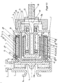
Vorbemerkung 1: Alle Zeichnungen zeigen einen axialen Längsschnitt durch die Pumpe. Die dabei zumeist geschnittenen Rotationskörper wurden - mit der Ausnahme von Wellen - der Übersichtlichkeit halber ohne umlaufende Kanten dargestellt.Preliminary note 1: All drawings show an axial longitudinal section through the pump. The mostly cut rotational bodies were - with the exception of waves - for the sake of clarity without circumferential edges shown.
Vorbemerkung 2: Aus Gründen der Montierbarkeit und der verschiedenen verwendeten Werkstoffe muss das im nachfolgenden als Pumpengehäuse (1) bezeichnete Bauteil in der Praxis aus mehreren Teilen aufgebaut sein. Einige davon sind von der zu fördernden Flüssigkeit benetzt und müssen entsprechend abgedichtet sein, andere nicht. Aus Gründen der einfacheren Darstellung ist das Pumpengehäuse (1) hier jedoch einteilig dargestellt.Preliminary note 2: For reasons of assembly and the various materials used, the component referred to below as the pump housing (1) must in practice be made up of several parts. Some of them are wetted by the liquid to be pumped and must be sealed accordingly, others not. For the sake of simplicity of illustration, the pump housing (1) is here shown in one piece.
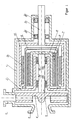
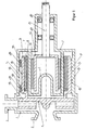
Eine erste bekannte Pumpe in üblicher Ausführung ist in
Im Pumpengehäuse (1') ist ein drehendes Pumpen-Laufrad (4') angeordnet, das die zu fördernde Flüssigkeit über den Saugstutzen (2') zugeführt bekommt und über den Druckstutzen (3') wieder unter Druckaufbau auswirft.In the pump housing (1 ') a rotating pump impeller (4') is arranged, which receives the liquid to be conveyed via the suction nozzle (2 ') and ejects via the discharge nozzle (3') again under pressure.
Die radiale Lagerung des Pumpen-Laufrades (4') erfolgt vermittels einer Laufradwelle (5') üblicherweise in Gleitlagern (9', 10'), deren feststehende Teile in einem Lagereinsatz (11') aufgenommen werden. Die Schmierung und Kühlung der Gleitlager (9'; 10') erfolgt durch die zu fördernde Flüssigkeit selbst.The radial bearing of the pump impeller (4 ') takes place by means of an impeller shaft (5') usually in plain bearings (9 ', 10'), the fixed parts in a bearing insert (11 ') are added. The lubrication and cooling of the sliding bearing (9 ', 10') takes place by the liquid to be pumped itself.
Die axiale Lagerung des Pumpen-Laufrades (4') und der übrigen damit verbundenen und drehenden Teile wird hier und im Folgenden nicht weiter betrachtet. Es sei hier nur angedeutet, dass neben einer mechanischen Lagerung mit Anlaufscheiben auch hydraulische Wirkprinzipien, die auf Druckdifferenzen basieren, wie auch eine magnetische Lagerung in Frage kommen können.The axial bearing of the pump impeller (4 ') and the other associated and rotating parts is not considered here and in the following. It is only indicated here that in addition to a mechanical bearing with thrust washers also hydraulic principles of action based on pressure differences, as well as a magnetic bearing can come into question.
Der Teil der Drehkupplung, der das antreibende Drehmoment durch eine Trennwand, die üblicherweise als dünnwandiger Spalttopf (12') ausgeführt wird, hindurch aufnimmt und über die Laufradwelle (5') an das Pumpen-Laufrad (4') weiterleitet, wird als Magnetrotor (6') bezeichnet. Dieser ist mit Permanentmagneten (7') bestückt, die wiederum vor dem korrosiven und evtl. auch abrasiven Angriff der Förderflüssigkeit mit einem zylinderförmigen Schutzmantel (8') flüssigkeitsdicht umgeben sein müssen. Es sei hier nur am Rande erwähnt, dass es erforderlich sein kann, einen etwa metallisch, sprich ferromagnetisch, ausgeführten Magnetrotor (6') auch vor Korrosion zu schützen ebenso wie die Welle (5').The part of the rotary coupling which receives the driving torque through a partition, which is usually designed as a thin-walled containment shell (12 '), therethrough and via the impeller shaft (5 ') to the pump impeller (4') passes, is referred to as a magnetic rotor (6 '). This is equipped with permanent magnets (7 '), which in turn must be surrounded before the corrosive and possibly also abrasive attack of the pumped liquid with a cylindrical protective jacket (8') liquid-tight. It should be mentioned only marginally that it may be necessary to protect an approximately metallic, that is to say ferromagnetic, magnet rotor (6 ') from corrosion as well as the shaft (5').
Der Teil der Drehkupplung, der das antreibende Drehmoment des Motors über die Antriebswelle (15') aufnimmt und weitergibt, wird üblich als Magnettreiber (13') bezeichnet. Auch er ist entsprechend mit Permanentmagneten (14') bestückt, die jedoch in Luft drehen und daher keinem besonderen Angriff unterliegen. Die radiale und axiale Lagerung des Magnettreibers erfolgt in handelsüblichen Wälzlagern (16').The part of the rotary coupling which receives and transmits the driving torque of the motor via the drive shaft (15 ') is commonly referred to as a magnet driver (13'). He is also equipped accordingly with permanent magnets (14 '), but rotate in air and therefore are not subject to any special attack. The radial and axial bearing of the magnetic drive takes place in commercial rolling bearings (16 ').
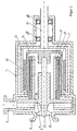
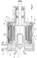
Eine weitere übliche Ausführung, insbesondere für kleinere Pumpen, zeigt
Bei dieser Konstruktion kann ein Lagereinsatz (11') kostengünstig entfallen. Das Pumpen-Laufrad (4') wird mit dem Magnetrotor (6'), den Permanentmagneten (7') und dem Schutzmantel (8') zu einem Teil zusammengefasst. Dieses drehende Laufrad-Magnetrotor-Einheit (19')wird hier auf einer feststehenden Achse (17') gleitend gelagert. Die Achse (17') selbst wird auf der einen Seite über Strömungsrippen (18') im Saugstutzen (2') befestigt, auf der anderen Seite in dem speziell ausgeformten Spalttopf (12') abgestützt.With this construction, a bearing insert (11 ') can be inexpensively eliminated. The pump impeller (4 ') is combined with the magnet rotor (6'), the permanent magnet (7 ') and the protective jacket (8') to a part. This rotating impeller magnetic rotor unit (19 ') is slidably mounted here on a fixed axle (17'). The axis (17 ') itself is fastened on one side via flow ribs (18') in the suction nozzle (2 '), supported on the other side in the specially shaped containment shell (12').
Die in
Des Weiteren erleichtert diese Bauweise insbesondere eine großzügig axial beabstandete radiale Lagerung des Pumpen-Laufrades (4'), was aufgrund der hohen hydraulischen Kräfte innerhalb der Pumpe stets anzustreben ist.Furthermore, this design facilitates in particular a generously axially spaced radial bearing of the pump impeller (4 '), which is always desirable due to the high hydraulic forces within the pump.
Seltener werden hingegen Magnetkupplungspumpen mit einem radial außen gelegenen Magnetrotor (6'), der ja flüssigkeitsberührt ist, und einem innen liegendem Magnetreiber (13') ausgeführt. Diese Ausführung sei als Bauart B bezeichnet.On the other hand, magnetic coupling pumps with a magnet rotor (6 ') located radially on the outside, which is in contact with the liquid, and an internal magnetic driver (13') are less frequently used. This embodiment is referred to as type B.
Solche Pumpen der Bauart B, die z.B. in der
Ein wichtiger Problembereich beim Betrieb der bisher vorgestellten Magnetpumpen, die also mit Gleitlagerungen versehen sind und das zu pumpende Medium selbst als deren Kühl- und Schmiermedium nutzen, ist das weitgehende oder völlige Ausbleiben eben dieser Flüssigkeit. Eine solche Mangelschmierung tritt dann auf, wenn sich höhere Gasanteile in der Flüssigkeit ansammeln, z.B. durch Kavitation vor der Pumpe, Trombeneintrag oder auch bei Schlürfbetrieb. Diese Gasanteile sammeln sich durch die Zentrifugalwirkung in der Pumpe in den radial innen gelegenen Hohlräumen des Pumpenkörpers an. Bei der herkömmlichen Bauweise It.
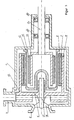
Einen technisch anderen und sehr sinnvollen Weg, nämlich die gefährdete Gleitlagerung radial möglichst weit nach außen zu verlegen, weist der Lösungsansatz einer "wellenlosen" Magnetpumpe wie in [4] beschrieben auf, welcher in
Dennoch bleibt der Vorschlag aus [4] technisch beschränkt. So findet die radiale Gleitlagerung der Laufrad-Magnetrotor-Einheit (19') im Spalttopf (12') selbst statt, der aber gerade an dieser Stelle als sehr dünnwandiges Bauteil ausgeführt werden muss. Darauf wird auch in [4] hingewiesen und es kann dort daher auch nicht auf stabilere zusätzliche Anfahr- bzw. Notlager (37') verzichtet werden, die nachteilig teils immer noch durch den Spalttopf (12') gebildet werden müssen. Weiterhin gestattet die Abstützung der Lagerung im dünnwandigen Spalttopf keine äußere Kühlung oder einen einfachen äußeren Zugang, etwa zur Lagertemperaturüberwachung oder zur Zwangsspülung.Nevertheless, the proposal from [4] remains technically limited. Thus, the radial slide bearing of the impeller magnetic rotor unit (19 ') takes place in the containment shell (12') itself, which, however, has to be executed at this point as a very thin-walled component. This is also pointed out in [4] and it is therefore not possible to dispense with more stable additional start-up or emergency bearings (37 ') which, disadvantageously, still partly have to be formed by the containment shell (12'). Furthermore, the support of the storage in thin-walled containment shell does not allow external cooling or easy external access, such as storage temperature monitoring or forced flushing.
Es bleibt festzustellen, dass im Falle einer Betriebsstörung, z.B. bei Kavitation vor der Pumpe, Trombeneintrag oder auch bei Schlürfbetrieb, eine Kreiselpumpe mit deutlich erhöhten Gasanteilen in der zu fördernden Flüssigkeit beaufschlagt wird. Diese Gasanteile sammeln sich durch die Zentrifugalwirkung in der Pumpe in den radial innen gelegenen Hohlräumen des Pumpenkörpers an. Bei herkömmlich ausgeführten Magnetkupplungspumpen befinden sich dort die Gleitlagerungen, die dann trocken fallen und dadurch häufig zerstört werden.It should be noted that in the event of a breakdown, e.g. cavitation in front of the pump, Trombeneintrag or snoring, a centrifugal pump is charged with significantly increased gas fractions in the liquid to be delivered. These gas components accumulate due to the centrifugal action in the pump in the radially inner cavities of the pump body. In conventionally designed magnetic drive pumps there are the sliding bearings, which then fall dry and are therefore often destroyed.
Davon ausgehend liegt der Erfindung die Aufgabe zugrunde, die radiale Lagerung im Bereich der Magnetkupplung einer gattungsgemäßen Kreiselpumpe zu verbessern. Zur Lösung dieser Aufgabe wird eine Kreiselpumpe mit den Merkmalen der Ansprüche 1 oder 3 vorgeschlagen.Based on this, the present invention seeks to improve the radial bearing in the magnetic coupling of a generic centrifugal pump. To solve this problem, a centrifugal pump with the features of
Durch die Erfindung, welche die einleitend beschriebenen Unvollkommenheiten nach dem Stand der Technik überwindet und bei der die radiale Lagerung der Laufrad-Magnetrotor-Einheit soweit wie möglich nach außen verlagert ist, werden u.a. folgende Vorteile erreicht:
- die Lagerung der Laufrad-Magnetrotor-Einheit wird im Falle einer gaseintragenden Betriebsstörung außerhalb des gefährdeten Innenbereiches sicher weiterbetreiben, wobei auch das Abschleudern von Restflüssigkeit nach außen, die dann zur Lagerschmierung dient, günstig ausgenutzt wird;
- die Lagerung befindet sich nahe an der äußeren Gehäusewand, wo durch Kühlrippen die sich etwa erhitzende, nach außen abgeschleuderte Restflüssigkeit wirksam gekühlt werden kann;
- es wird eine vergleichsweise hohe Gleitgeschwindigkeit in den Lagern erzielt, so dass die Lagerung trotz der üblichen niedrigen Pumpendrehzahlen (in der Regel nur 1000 1/min bis 3000 1/min) auch bei niedrigen Fördermediumsviskositäten (oft wasserähnlich) in den Zustand der berührungsfreien Gleitung gelangen kann und damit das Mischreibungsgebiet herkömmlicher Gleitlagerungen in Magnetkupplungspumpen vermieden wird;
- es wird ein einfacher äußerer Zugang zu den Gleitlagern möglich und damit die Möglichkeit einer extern versorgten Lagerschmierung und/oder einer sensorischen Überwachung der Lager geschaffen;
- der Spalttopf findet nicht mehr als abstützendes Bauteil Verwendung, so dass er - sich der magnetischen Momentenübertragung unterordnend - stets dünnwandig ausgeführt werden kann und dennoch die Gefahr einer Überlastung und Deformation nicht besteht;
- des Weiteren werden Anlauf- und Notlager verzichtbar.
- the bearing of the impeller magnetic rotor unit will continue to operate safely in the event of a gas-bearing malfunction outside the vulnerable interior, with the centrifuging of residual liquid to the outside, which then serves for bearing lubrication, is used to advantage;
- the storage is close to the outer housing wall, where by cooling fins, the approximately heated, thrown off to the outside residual liquid can be effectively cooled;
- a comparatively high sliding speed is achieved in the bearings, so that the bearings reach the state of non-contact sliding even at low pumped medium viscosities (often similar to water) despite the usual low pump speeds (generally only 1000 l / min to 3000 l / min) can and thus the mixed friction region of conventional sliding bearings in magnetic coupling pumps is avoided;
- it is a simple external access to the bearings possible and thus created the possibility of externally powered bearing lubrication and / or sensory monitoring of the bearings;
- the containment can no longer be used as a supporting component, so that it can always be made thin-walled, subordinating to the transmission of magnetic moments, and yet there is no danger of overloading and deformation;
- Furthermore, start-up and emergency camps are dispensable.
Wenn der feststehende Teil der Gleitlagerung insgesamt auf der innenseitigen Wandfläche des Pumpengehäuses angeordnet ist oder durch die Gehäusewand oder Abschnitte der Gehäusewand des Pumpengehäuses selbstständig gebildet wird, können dadurch auf großer axialer Länge insgesamt hohe radiale Lagerkräfte übertragen werden und ein ruhiger Gleichlauf der Laufrad-Magnetrotor-Einheit erzielt werden. Im Falle mehrerer axial beabstandeter Gleitlagerabschnitte befinden sich diese vorzugsweise etwa auf dem gleichen radialen Niveau, um die Gleichlaufeigenschaften und die Trockenlauffähigkeit der Lagerung weiter zu verbessern. Grundsätzlich ist es im Sinne der Erfindung möglich, auch das Pumpen-Laufrad als solches zu lagern, und zwar insbesondere zur Aufnahme axialer Lagerkräfte. Es können zusätzlich auch radiale Lagerkräfte am Pumpenlaufrad aufgenommen werden, z.B. um eine Verbesserung von Notlauf- und/oder Anfahreigenschaften zu erzielen. Beste Gleichlaufbedingungen werden allerdings erreicht, wenn das Pumpen-Laufrad radial berührungs- oder zwangsfrei rotierbar ist.If the fixed part of the slide bearing is arranged on the inside wall surface of the pump housing as a whole or is formed independently by the housing wall or sections of the housing wall of the pump housing, high radial bearing forces can be transmitted over a large axial length and a smooth synchronization of the impeller magnet rotor Unit can be achieved. In the case of a plurality of axially spaced sliding bearing sections, these are preferably located approximately at the same radial level in order to further improve the running characteristics and the dry running capability of the bearing. Basically, it is within the meaning of the invention possible to store the pump impeller as such, in particular for receiving axial bearing forces. In addition, radial bearing forces can also be absorbed on the pump impeller, e.g. to achieve an improvement of runflat and / or starting properties. However, best synchronization conditions are achieved if the pump impeller can be rotated radially without contact or force.
Wenn ein Flüssigkeitsrückhalteraum im Bereich der Gleitlagerung der Laufrad-Magnetrotor-Einheit vorgesehen wird, wird dadurch die Trockenlaufgefahr verringert).If a liquid retention space is provided in the area of the sliding bearing of the impeller magnetic rotor unit, thereby the risk of dry running is reduced).
Wenn die Gleitlagerung der Laufrad-Magnetrotor-Einheit in ihrem rotierenden Teil als durchgehende Hülse, gegebenenfalls in Gestalt einer Formmasse ausgeführt wird, können dadurch bestmögliche Materialpaarungen und ein Schutz der Permanentmagnete des Magnetrotors verbessert bzw. vereinfacht werden.If the sliding bearing of the impeller magnetic rotor unit is carried out in its rotating part as a continuous sleeve, optionally in the form of a molding compound, thereby best possible material pairings and protection of the permanent magnets of the magnet rotor can be improved or simplified.
Wenn der rotierende Teil der Gleitlagerung der Laufrad-Magnetrotor-Einheit auf seinem Außenumfang Ausnehmungen oder Erhöhungen aufweist, können dadurch die Gleiteigenschaften verbessernde Flüssigkeitsbewegungen erzeugt werden.If the rotating part of the sliding bearing of the impeller magnetic rotor unit has recesses or elevations on its outer circumference, thereby the sliding properties improving liquid movements can be generated.
Wenn die außenseitige Wandung des Pumpengehäuses im Bereich des feststehenden Teils der Gleitlagerung der Laufrad-Magnetrotor-Einheit mit Kühlrippen oder einem Kühlmantel versehen ist, können überhitzungsbedingte Lagerschäden vermieden werden.If the outside wall of the pump housing is provided in the region of the fixed part of the sliding bearing of the impeller magnetic rotor unit with cooling fins or a cooling jacket, overheating-related bearing damage can be avoided.
Wenn in der Wandung des Pumpengehäuses im Bereich des feststehenden Teils der Gleitlagerung der Laufrad-Magnetrotor-Einheit Zugänge für externe Schmiermittel oder Überwachungssensoren vorgesehen sind, kann hierdurch eine Schmierung oder Notschmierung bzw. eine Verschleißkontrolle dieser Gleitlagerung erreicht werden.If accesses for external lubricants or monitoring sensors are provided in the wall of the pump housing in the region of the stationary part of the sliding bearing of the impeller magnetic rotor unit, lubrication or emergency lubrication or wear control of this slide bearing can be achieved.
Wenn die Pumpengehäusewandung mehrschichtig aufgebaut ist und die innerste Materialschicht aus einem korrosions- oder abrasionsbeständigen Werkstoff besteht, wird hiermit die Langlebigkeit auch bei schwierigen Fördermedien verbessert.If the pump housing wall has a multilayer structure and the innermost material layer consists of a corrosion- or abrasion-resistant material, the longevity is improved even with difficult pumped media.
Die vorerwähnten Ausgestaltungen einer Kreiselpumpe sind auch unabhängig vom Anspruch 1 von eigenständiger erfinderischer Bedeutung.The aforementioned embodiments of a centrifugal pump are independent of
Wenn der Magnettreiber über mindestens ein im Bereich des Innenraumes der Laufrad-Magnetrotor-Einheit angeordnetes Lager verfügt, kann dadurch die Pumpenbaulänge trotz eigenständiger Lagerung des Magnettreibers innerhalb der Pumpe erheblich verkürzt werden. Für die Magnettreiber-Lagerung werden bevorzugt Wälzlager verwendet. Die Wälzlagerung des Magnettreibers bleibt von der Förderflüssigkeit unberührt. Hierzu dient vorzugsweise ein ansich bekannter, zwischen dem Magnetrotor und dem Magnettreiber angeordneter Spalttopf. Der Magnettreiber weist vorzugsweise eine zur Antriebsseite hin offene Topfform auf, um das mindestens eine Lager des Magnetrotors innerhalb des Pumpengehäuses aufzunehmen. Eine besonders vorteilhafte Lagerung des Magnettreibers wird durch einen durchgehend hohlen Kragzapfen erreicht, durch den die Antriebswelle des Magnettreibers geführt ist, und der vorzugsweise an mindestens einer inneren oder äußeren Fläche an mindestens einem seiner Endbereiche ein Lager für den Magnettreiber trägt. Verjüngungen in diesen Endbereichen erleichtern die Unterbringung derartiger Lager auf kleinem Raum. Wenn die Verjüngung von der Wurzel des Kragzapfens ausgehend erfolgt, können bei leichter Bauweise hohe Lagerkräfte aufgenommen werden.If the magnet driver has at least one arranged in the region of the interior of the impeller magnetic rotor unit bearing, thereby the pump length can be significantly reduced despite independent storage of the magnetic driver within the pump. For the magnetic drive bearing bearings are preferably used. The rolling bearing of the magnetic driver remains unaffected by the pumped liquid. For this is preferably used a ansich known, arranged between the magnet rotor and the magnet driver split pot. The magnet driver preferably has an open towards the drive side cup shape to receive the at least one bearing of the magnet rotor within the pump housing. A particularly advantageous mounting of the magnetic driver is achieved by a hollow hollow cantilever, through which the drive shaft of the magnet driver is guided, and which preferably carries on at least one inner or outer surface at least one of its end portions a bearing for the magnetic driver. Tapering in these end areas facilitate the placement of such bearings in a small space. When the taper is made from the root of the cantilever, high bearing forces can be absorbed in a lightweight construction.
Die zumindest teilweise Lagerung des Magnettreibers innerhalb des von der Laufrad-Magnetrotor-Einheit aufgespannten Raumes sowie die Ausgestaltungen einer derartigen Lagerung sind von eigenständiger erfinderischer Bedeutung.The at least partial storage of the magnetic driver within the space defined by the impeller magnetic rotor unit and the embodiments of such storage are of independent inventive significance.
Die vorgenannten sowie die beanspruchten und in den Ausführungsbeispielen beschriebenen erfindungsgemäß zu verwendenden Bauteile unterliegen in ihrer Größe, Formgestaltung, Materialauswahl und technischen Konzeption keinen besonderen Ausnahmebedingungen, so dass die in dem Anwendungsgebiet bekannten Auswahlkriterien uneingeschränkt Anwendung finden können.The above-mentioned and the claimed components to be used according to the invention described in the exemplary embodiments are not subject to special conditions of size, shape, material selection and technical design, so that the selection criteria known in the field of application can be used without restriction.
Weitere Einzelheiten, Merkmale und Vorteile des Gegenstandes der Erfindung ergeben sich aus den Unteransprüchen sowie aus der nachfolgenden Beschreibung der zugehörigen Zeichnung, in der - beispielhaft - ein bevorzugtes Ausführungsbeispiel der erfindungsgemäßen Anordnung einer Kreiselpumpe mit koaxialer Magnetkupplung dargestellt ist. In der Zeichnung zeigen:
- Fig. 5
- eine erste Ausführungsform einer erfindungsgemäßen Kreiselpumpe im Axialschnitt - schematisiert;
- Fig. 6
- eine zweite Ausführungsform;
- Fig. 7
- eine dritte Ausführungsform;
- Fig. 8
- eine vierte Ausführungsform;
- Fig. 9
- eine fünfte Ausführungsform;
- Fig. 10
- eine sechste Ausführungsform;
- Fig. 11
- eine siebte Ausführungsform;
- Fig. 12
- eine achte Ausführungsform;
- Fig. 13
- eine neunte Ausführungsform;
- Fig. 14
- eine zehnte Ausführungsform sowie
- Fig. 15
- eine elfte Ausführungsform.
- Fig. 5
- a first embodiment of a centrifugal pump according to the invention in axial section - schematized;
- Fig. 6
- a second embodiment;
- Fig. 7
- a third embodiment;
- Fig. 8
- a fourth embodiment;
- Fig. 9
- a fifth embodiment;
- Fig. 10
- a sixth embodiment;
- Fig. 11
- a seventh embodiment;
- Fig. 12
- an eighth embodiment;
- Fig. 13
- a ninth embodiment;
- Fig. 14
- a tenth embodiment as well
- Fig. 15
- an eleventh embodiment.
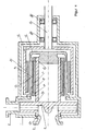
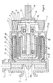
Den Ausführungsformen ist gemeinsam, dass sie ein einen Saugstutzen 2 und einen Druckstutzen 3 aufweisendes Pumpengehäuse 1 aufweisen, wobei ein Pumpen-Laufrad 4 koaxial zum Saugstutzen gelagert ist und in radialer Richtung mit dem Druckstutzen 3 fluidisch verbunden ist. Das Pumpen-Laufrad 4 weist antriebsseitig einen Magnetrotor 6 auf, mit dem es zusammen eine zur Antriebsseite hin offene Laufrad-Magnetrotor-Einheit bildet. Diese weist auf ihrem Außenumfang den rotierenden Teil 9 einer Gleitlagerung auf, während der feststehende Teil 10 dieser Gleitlagerung an der Innenwand 20 des Pumpengehäuses 1 angeordnet ist. Auf der radialen Innenseite trägt der Magnetrotor 6 Permanentmagnete 7. Diese stehen Permanentmagneten 14 mit radialem Abstand gegenüber, welche auf der Außenfläche eines etwa topfförmigen Magnettreibers 13 angeordnet sind. Zwischen dem Magnetrotor und dem Magnettreiber ist in allen Ausführungsbeispielen eine Trennwand, ggf. in Gestalt eines so genannten Spalttopfes 12, zwischengefügt, welche/r den Magnettreiber gegenüber dem flüssigkeitsbenetzten Inneren der Pumpe trocken hält. Der Magnettreiber 13 ist an zwei axial beabstandeten Stellen über Wälzlager 16a und 16b gelagert. Diese Lagerung findet bei allen Ausführungsbeispielen - wenn auch nicht zwingend - jeweils gegenüber dem Pumpengehäuse 1 statt, wobei diese Lagerung bei den Ausführungsformen nach
Der äußere Umfang der Laufrad-Magnetrotor-Einheit 19 kann nun - bei völliger Gestaltungsfreiheit und in großzügiger axialer Ausdehnung - zur Aufnahme des rotierenden Teils 9 der Gleitlagerung genutzt werden (
Da alle Teile der koaxialen Magnetkupplung radial weiter innen gelegen sind, kann der feststehende Teil 10 der Gleitlagerung ohne weiteres direkt an die stabile innere Gehäusewandung 20 des Pumpengehäuses 1 herangeführt werden (
Für eine wirksame Gleitlagerung ist es dabei unerheblich, ob In zwei expliziten Lagerstellen 9,10a und 9,10b gelagert wird (
Eine Anordnung gemäß Anspruch 1 bietet nicht nur erhebliche technologische Vorteile, sondern führt auch zu einem äußerst einfachen Aufbau der gesamten Pumpe.An arrangement according to
Im Falle einer - in der Praxis häufigen - Betriebsstörung der Pumpe über massiven Gaseintrag (Luft oder verdampfte Förderflüssigkeit in Folge Kavitation) wird sich die in der Pumpe verbleibende Restflüssigkeit als abgeschleuderter Ring am äußeren Umfang im Pumpengehäuse 1 sammeln. Bei einer entsprechenden Pumpe ist genau hier nun die Gleitlagerung 9,10 angeordnet, die mit der Restflüssigkeit bei ausreichender Kühlung beliebig lange betrieben werden kann. Es ist allerdings bei sehr geringen Restmengen, die sich tendenziell bei großen Förderhöhen der Pumpe und geringem statischen Gegendruck einstellen, nicht auszuschließen, dass diese axial entweichen können, um sich auf noch höhere radiale Niveaus im Laufrad zu begeben. Dies kann über eine Sperre in Form eines Umlaufringes 21 verhindert werden, in
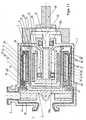
Die Erfindung kann auch dazu ausgenutzt werden, die axiale Ausdehnung der Pumpe erheblich zu verkürzen. Dies ist möglich, indem der Magnettreiber 13 nicht im Pumpengehäuse 1 gelagert wird, sondern direkt auf den Wellenzapfen der Antriebsmaschine gesetzt wird, also letztlich durch die Antriebsmaschine gelagert wird. Dies ist in aller Regel ein Elektromotor. Dabei wird der Elektromotor direkt an die Pumpe geflanscht, was als "Blockbauweise" bekannt ist.
Vorteil dieser Konstruktion ist neben dem Effekt der axialen Verkürzung die Ersparnis der beiden Wälzlager 16. Nachteil dieser Konstruktion ist, dass der Magnettreiber 13 nicht mehr zur Pumpe gehörig ist und damit eine vollständige Montage der Pumpe erst dann erfolgen kann, wenn auch der antreibende Motor vorhanden ist. Dessen Baugröße ist aber zumindest bei industriellen Pumpen zunächst eine unbekannte Größe und wird erst aufgrund der Kundenangaben bestimmbar. Damit wird der Zeitpunkt der Endmontage der Pumpe zwingend hinter diesen Zeitpunkt verlegt und wird zudem noch zu einer individuellen Montage mit den bekannten wirtschaftlichen Nachteilen.The invention can also be exploited to significantly shorten the axial extent of the pump. This is possible by the
Advantage of this construction is in addition to the effect of axial shortening the savings of the two bearings 16. The disadvantage of this design is that the
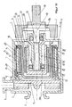
Auf dem Wege zu einer besseren Lösung wird gemäß
Das Wellenende 25 bei einer solchen axial verkürzten Bauweise kann vorteilhaft gemäß
Der rotierende Teil 9 der Gleitlagerung muss nicht notwendigerweise aus zwei definierten Lagerhülsen a und b bestehen oder aus dem Magnetrotor 6 selbst, sondern kann
Dies bietet wirtschaftliche Vorteile, insbesondere dann, wenn diese Bauteile gemäß
Der angestrebten völlig kontaktfreien und damit verschleißfreien und reibungsarmen Gleitung des Laufrad-Magnetrotor-Systems 19 im Pumpengehäuse 1 kommt die hohe Umfangsgeschwindigkeit dieser Anordnung entgegen. Durch zusätzliche grübchenartige Ausnehmungen oder Erhöhungen auf der Oberfläche der rotierenden Gleitlagerung 9, z.B. also auf der Hülse 29 oder der Formmasse 30 können so genannte Taylor-Wirbel im Gleitspalt und im angrenzenden Rotationsraum der Flüssigkeit erzeugt werden, die zur Stabilisierung und zur Kontaktfreiheit der Gleitlagerung beitragen. Diese Ausnehmungen oder Erhöhungen werden mit
Insbesondere wenn in der Pumpe im Falle einer Betriebsstörung nur noch ein Flüssigkeitsring 23 rotiert und ein Strom an frischer Schmierflüssigkeit ausbleibt, wird sich diese Restflüssigkeit in der Gleitlagerung aufgrund von Reibung soweit erhitzen, bis ein Wärmetransportgleichgewicht mit dem Pumpengehäuse 1 erreicht ist. Aufgrund des direkten Kontaktes der Gleitlagerung 9, 10 mit dem Pumpengehäuse 1 besteht hier durch Anbringung von äußeren Kühlrippen 32, wie sie in
Um die Mangelschmierung der Gleitlagerung 9, 10 auch im Falle einer entsprechenden Betriebsstörung zu verhindern, wird die Versorgung mit externer Schmierflüssigkeit laut
Viele ausgeführte Magnetkupplungspumpen, die aufgrund der hermetischen Abdichtung des Pumpeninneren gerade zur Förderung aggressiver, abrasiver und gefährlicher Flüssigkeiten besonders geeignet sind, sind im benetzten Bereich des Pumpengehäuses 1 mit etwa einer Kunststoffschicht ausgekleidet oder aus mehreren - in der Regel zwei - Werkstoffschalen aufgebaut. Letztlich muss dann die innerste Materialschicht 35 die gewünschten Eigenschaften gegenüber der Flüssigkeit aufweisen, während die äußeren Schalen eher der Formgebung und Stabilität gegenüber dem Innendruck der Pumpe dienen.
- 11
- Pumpengehäusepump housing
- 22
- Saugstutzensuction
- 33
- Druckstutzenpressure port
- 44
- Pumpen-LaufradImpeller
- 55
- Laufradwelleimpeller shaft
- 66
- Magnetrotormagnet rotor
- 77
- Permanentmagnet (Rotor)Permanent magnet (rotor)
- 88th
- Schutzmantelmantle
- 99
- rotierendes Gleitlagerrotating plain bearing
- 9a9a
- rotierendes Gleitlager, laufradseitigrotating plain bearing, impeller side
- 9b9b
- rotierendes Gleitlager, antriebsseitigrotating plain bearing, drive side
- 1010
- feststehendes Gleitlagerfixed plain bearing
- 10a10a
- feststehendes Gleitlager, laufradseitigFixed plain bearing, impeller side
- 10b10b
- feststehendes Gleitlager, antriebsseitigFixed slide bearing, drive side
- 1111
- Lagereinsatzbearing insert
- 1212
- Spalttopfcontainment shell
- 1313
- Magnettreibermagnetic driver
- 1414
- Permanentmagnet (Treiber)Permanent magnet (driver)
- 1515
- Antriebswelledrive shaft
- 16a16a
- Wälzlager, laufradseitigRolling bearing, impeller side
- 16a16a
- Wälzlager, antriebsseitigRolling bearing, drive side
- 1717
- Achseaxis
- 1818
- Strömungsrippenflow ribs
- 1919
- Laufrad-Magnetrotor-EinheitImpeller-magnetic rotor unit
- 2020
- Innenseitige Wand des PumpengehäusesInside wall of the pump housing
- 2121
- Umlaufringcircumferential ring
- 2222
- FlüssigkeitsrückhalteraumFluid retention area
- 2323
- rotierende Menge von Restflüssigkeitrotating amount of residual fluid
- 2424
- Innenbereich des SpalttopfesInterior of the containment shell
- 2525
- Wellenendeshaft end
- 2626
- SchwungmasseInertia
- 2727
- Zapfenteil einer PumpenkupplungSpigot part of a pump coupling
- 2828
- Wellenzapfenshaft journal
- 2929
- Hülseshell
- 3030
- Formmassemolding compound
- 3131
- Ausnehmungenrecesses
- 3232
- Kühlrippencooling fins
- 3333
- Zugang für SchmierflüssigkeitAccess for lubricating fluid
- 3434
- Zugang für SensorenAccess for sensors
- 3535
- Innerste MaterialschichtInnermost material layer
- 3636
- Dichtmittelsealant
- 3737
- Anfahr- bzw. NotlagerApproach or emergency camp
- 3838
- Außenumfang des Laufrad-Magnetrotor-SystemsOuter circumference of the impeller magnetic rotor system
- 3939
- Kragzapfencollar journal
- 39a39a
- Verjüngungrejuvenation
- 39b39b
- Verjüngungrejuvenation
-
[1] Broschüre der
Firma WERNERT-PUMPEN GMBH
D-45476 Mülheim an der Ruhr Chemienormpumpe aus Kunststoff mit Magnetkupplung - Typenreihe NM Ausgabe 687/02[1] Brochure of
Company WERNERT-PUMPEN GMBH
D-45476 Mülheim an der Ruhr Standardized chemical plastic pump with magnetic coupling - Type series NM Edition 687/02 -
[2] Broschüre der
Firma IWAKI Pumpen
Iwaki magnetgetriebene Pumpen - Serie MDM
printed in Japan 99.11.ITN[2] Brochure of
Company IWAKI pumps
Iwaki Magnetic Pumps - MDM Series
printed in Japan 99.11.ITN -
[3] Broschüre der
Firma CP-Pumpen AG CH-4800 Zofingen:
Magnetkupplungspumpe MKP, metallisch[3] Brochure of
Company CP-Pumpen AG CH-4800 Zofingen:
Magnetic coupling pump MKP, metallic -
[4]
Robert Neumaier: Hermetische Pumpen Verlag und Bildarchiv W.H. Faragallah, 1994 ISBN-3-929682-05-2 Kapitel 3.7.12 Wellenlose Magnetkupplungs-Kreiselpumpen S. 356 ff Robert Neumaier: Hermetic pumps Verlag und Bildarchiv WH Faragallah, 1994 ISBN-3-929682-05-2 Chapter 3.7.12 Wave-less magnetic-coupling centrifugal pumps p. 356 ff
Claims (21)
- Rotary pump- comprising a static and enclosed containment of the pumped liquid in the interior of the pump in the form of a housing (1),- with a contact-free permanent magnet coaxial rotary coupling (6, 7; 13, 14) for transferring a drive moment into the interior of the pump housing- with a pump impeller (4) which forms, together with a magnetic rotor (6) which carries permanent magnets (7), a pot-shaped component (impeller-magnetic rotor unit 19) which is mounted on sliding bearings and is open toward the drive side,- and wherein the magnetic force lines of the driving part of the rotary coupling (magnetic driver 13 and permanent magnets 14) face radially outwardly and the magnetic force lines of the part of the rotary coupling (magnetic rotor 6 and permanent magnets 7) connected to the pump impeller (4) face radially inwardly,characterised in that, for radial mounting of the impeller-magnetic rotor unit (19)- the rotating part (9; 9a, 9b) of a sliding bearing mounting is altogether arranged along the outer periphery (38) of the magnetic rotor (6) and is firmly connected thereto or is formed by the outer periphery or sections of the outer periphery (38) of the magnetic rotor (6).
- Rotary pump according to claim 1, characterised in that the fixed part (10; 10a, 10b) of the sliding bearing mounting is arranged on the internal wall surface (20) of the pump housing (1) or is provided by the housing wall or sections of the housing wall (20) of the pump housing (1).
- Rotary pump according to claim 1 or 2, wherein a plurality of axially spaced sliding bearing sections (9a, 10a; 9b, 10b) is provided which are arranged at approximately the same radial level.
- Rotary pump according to one of the claims 1 to 3, characterised in that the pump impeller (4) can rotate without radial contact or constraint.
- Rotary pump according to one of the claims 1 to 4, characterised in that arranged between the pump impeller (4) and the sliding bearing mounting (9, 10) is a peripheral ring (21) or collar such that the inner dimension thereof is smaller than the contact diameter of the sliding bearing mounting (9, 10) and thereby a fluid retention chamber (22) is obtained in the region of the sliding bearing mounting (9, 10) both on rotation and on standstill of the pump impeller (4).
- Rotary pump according to one of the claims 1 to 5, characterised in that the rotating part (9; 9a, 9b) of the sliding bearing mounting is configured as an axially continuous sleeve (29) or an axially continuous cast or pressed moulding mass (30).
- Rotary pump according to claim 6, characterised in that the sleeve (29) or the moulding mass (30) have been or are applied, formed or sealed with sealing means (36) such that said sleeve or moulding mass become part of a protective jacket (8) for the permanent magnet (7) and/or the magnetic rotor (6).
- Rotary pump according to one of the claims 1 to 7, characterised in that the rotating part (9; 9a, 9b) of the sliding bearing mounting is provided on the outer periphery of said rotating part with a plurality of local recesses (31) or elevations which favour the formation of stabilising flow eddies in the sliding bearing mounting.
- Rotary pump according to one of the claims 1 to 8, characterised in that the external wall of the pump housing (1) is provided in the region of the fixed part (10) of the sliding bearing mounting with cooling ribs (32).
- Rotary pump according to one of the claims 1 to 9, characterised in that the fixed part (10) of the sliding bearing mounting can be supplied through one or more accessways (33) in the wall of the pump housing (1) with external lubricant.
- Rotary pump according to one of the claims 1 to 10, characterised in that the fixed part (10) of the sliding bearing mounting can be monitored through one or more accessways (34) by sensors in the wall of the pump housing (1).
- Rotary pump according to one of the claims 1 to 11, characterised in that the wall of the pump housing (1) is made from a plurality of material layers and the innermost material layer (35) is made from a corrosion-proof and/or abrasion-proof material.
- Rotary pump according to one of the claims 1 to 12, wherein arranged between the magnetic rotor (6) and the magnetic driver (13) is a separating wall which faces, with the opening thereof, the drive side of the pump and separates the fluid in the interior of the pump from the magnetic driver (13), characterised in that- the magnetic driver (13) is mounted in at least one bearing connected to the pump, for example, a roller bearing (16),- at least one impeller-side bearing, for example, a roller bearing (16a) is situated in the inner region (24) of the pump housing and- the magnetic driver (13) is mounted without contact with the separating wall.
- Rotary pump according to claim 13, characterised in that the at least one impeller-side bearing is situated in the internal region of a magnetic driver (13) which is hollow internally.
- Rotary pump according to claim 13 or 14, characterised in that the internal ring is fixed by the impeller-side bearing and the associated external ring rotates with the bearing mounted magnetic driver (13).
- Rotary pump according to claim 15, characterised in that a drive-side bearing, for example, a roller bearing (16b) is provided, the internal ring of which rotates with the bearing mounted drive shaft (15) and is fixed to the associated external ring.
- Rotary pump according to one of the claims 13 to 16, characterised in that a continuous hollow protruding journal (39) is provided extending inwardly from the drive side into the pump housing (1) in order to receive the drive shaft (15) and is or can be connected to the pump housing.
- Rotary pump according to claim 17, characterised in that the hollow protruding journal (39) has at least one narrowing (39a; 39b) at one of the end regions thereof.
- Rotary pump according to one of the claims 13 to 18, characterised in that the region of the drive-side end (25) of the drive shaft (15) is configured to comprise an inertial mass (26) or is provided therewith.
- Rotary pump according to one of the claims 13 to 19, characterised in that the region of the drive-side end (25) of the drive shaft (15) is configured so that said region can optionally be detachably coupled to an inertial mass (26), a journal part (27) of a pump coupling and/or to a shaft journal (28).
- Rotary pump according to one of the claims 13 to 20, characterised in that the magnetic driver (13) comprises a pot form which is open toward the drive side.
Priority Applications (1)
| Application Number | Priority Date | Filing Date | Title |
|---|---|---|---|
| EP08003862A EP1965081B1 (en) | 2006-03-31 | 2007-03-29 | Centrifugal pump with coaxial magnetic coupling |
Applications Claiming Priority (2)
| Application Number | Priority Date | Filing Date | Title |
|---|---|---|---|
| DE202006005189U DE202006005189U1 (en) | 2006-03-31 | 2006-03-31 | Centrifugal pump with coaxial magnetic coupling |
| PCT/EP2007/002814 WO2007112938A2 (en) | 2006-03-31 | 2007-03-29 | Rotary pump with coaxial magnetic coupling |
Related Child Applications (2)
| Application Number | Title | Priority Date | Filing Date |
|---|---|---|---|
| EP08003862A Division EP1965081B1 (en) | 2006-03-31 | 2007-03-29 | Centrifugal pump with coaxial magnetic coupling |
| EP08003862.3 Division-Into | 2008-03-01 |
Publications (2)
| Publication Number | Publication Date |
|---|---|
| EP2002126A2 EP2002126A2 (en) | 2008-12-17 |
| EP2002126B1 true EP2002126B1 (en) | 2010-06-23 |
Family
ID=38375284
Family Applications (2)
| Application Number | Title | Priority Date | Filing Date |
|---|---|---|---|
| EP08003862A Not-in-force EP1965081B1 (en) | 2006-03-31 | 2007-03-29 | Centrifugal pump with coaxial magnetic coupling |
| EP07723756A Not-in-force EP2002126B1 (en) | 2006-03-31 | 2007-03-29 | Rotary pump with coaxial magnetic coupling |
Family Applications Before (1)
| Application Number | Title | Priority Date | Filing Date |
|---|---|---|---|
| EP08003862A Not-in-force EP1965081B1 (en) | 2006-03-31 | 2007-03-29 | Centrifugal pump with coaxial magnetic coupling |
Country Status (9)
| Country | Link |
|---|---|
| US (1) | US8162630B2 (en) |
| EP (2) | EP1965081B1 (en) |
| JP (1) | JP5461172B2 (en) |
| KR (1) | KR101410628B1 (en) |
| CN (1) | CN101415950B (en) |
| AT (2) | ATE449263T1 (en) |
| DE (3) | DE202006005189U1 (en) |
| ES (1) | ES2335946T3 (en) |
| WO (1) | WO2007112938A2 (en) |
Cited By (1)
| Publication number | Priority date | Publication date | Assignee | Title |
|---|---|---|---|---|
| DE102009060549A1 (en) * | 2009-12-23 | 2011-06-30 | Wilo Se, 44263 | EC motor centrifugal pump |
Families Citing this family (44)
| Publication number | Priority date | Publication date | Assignee | Title |
|---|---|---|---|---|
| DE102007054233B4 (en) | 2007-11-12 | 2010-06-10 | Ika-Werke Gmbh & Co. Kg | Device for dispersing or homogenizing |
| CN101868203B (en) | 2007-11-21 | 2014-10-22 | 史密夫及内修公开有限公司 | Wound dressing |
| DE102008008290A1 (en) | 2008-02-07 | 2009-08-20 | H. Wernert & Co. Ohg | Impeller arrangement for pump, has plate or ring-like impeller body with two front sides, where multiple shovels are provided, which are fixed on former front surface |
| JP4681625B2 (en) | 2008-02-22 | 2011-05-11 | 三菱重工業株式会社 | Blood pump and pump unit |
| EP2180583B1 (en) * | 2008-10-24 | 2012-08-08 | Biazzi Sa | Device with mixing vessel |
| KR100935707B1 (en) * | 2009-04-30 | 2010-01-07 | 케이이티주식회사 | Magnetic drive-type sealless pump |
| KR100990096B1 (en) | 2009-06-04 | 2010-10-29 | 강선희 | Transport system with magnetic module |
| WO2011131251A1 (en) * | 2010-04-19 | 2011-10-27 | Pierburg Pump Technology Gmbh | Electric motor-vehicle coolant pump |
| JP4875783B1 (en) * | 2011-09-15 | 2012-02-15 | 三菱重工業株式会社 | Magnetic coupling pump and pump unit equipped with the same |
| TW201317459A (en) * | 2011-10-26 | 2013-05-01 | Assoma Inc | Permanent magnet canned pump structure improvement |
| CN102352848A (en) * | 2011-10-31 | 2012-02-15 | 神华集团有限责任公司 | Magnetic pump |
| TW201320547A (en) * | 2011-11-03 | 2013-05-16 | Assoma Inc | Structural improvement for magnetic driven pump |
| PL2604863T3 (en) * | 2011-12-13 | 2017-12-29 | Eagleburgmann Germany Gmbh & Co. Kg | Rotary compessor |
| US8651240B1 (en) | 2012-12-24 | 2014-02-18 | United Technologies Corporation | Pressurized reserve lubrication system for a gas turbine engine |
| US8905729B2 (en) | 2011-12-30 | 2014-12-09 | Peopleflo Manufacturing, Inc. | Rotodynamic pump with electro-magnet coupling inside the impeller |
| US8905728B2 (en) | 2011-12-30 | 2014-12-09 | Peopleflo Manufacturing, Inc. | Rotodynamic pump with permanent magnet coupling inside the impeller |
| CN102931809A (en) * | 2012-11-27 | 2013-02-13 | 镇江市江南矿山机电设备有限公司 | Interaxial permanent magnet coupling mechanism |
| CN103023241A (en) * | 2012-11-27 | 2013-04-03 | 镇江市江南矿山机电设备有限公司 | Interaxial permanent magnet coupling mechanism |
| CN102931810A (en) * | 2012-11-27 | 2013-02-13 | 镇江市江南矿山机电设备有限公司 | Interaxial permanent magnet coupling mechanism |
| CN103401396B (en) * | 2013-06-14 | 2016-07-06 | 宝鸡泰华磁机电技术研究所有限公司 | Interior radiation ring type permanent magnet clutch |
| KR101828544B1 (en) * | 2013-12-13 | 2018-03-29 | 한화파워시스템 주식회사 | A compressor assembly |
| US9771938B2 (en) | 2014-03-11 | 2017-09-26 | Peopleflo Manufacturing, Inc. | Rotary device having a radial magnetic coupling |
| EP3332126A4 (en) * | 2015-08-05 | 2019-03-27 | Wade Spicer | Magnetic drive, seal-less pump |
| DE102016200013B4 (en) | 2016-01-04 | 2022-11-03 | Röchling Automotive SE & Co. KG | pump |
| CN107327570B (en) * | 2016-04-28 | 2018-10-19 | 哈尔滨歌瑞得莱机器人制造有限公司 | Synchronize double magnet ring driving sealing devices |
| CN109416058B (en) | 2016-07-04 | 2021-05-07 | 阿莫泰克有限公司 | Water pump |
| WO2018008896A1 (en) * | 2016-07-04 | 2018-01-11 | 주식회사 아모텍 | Water pump |
| DE202016105312U1 (en) * | 2016-09-23 | 2018-01-09 | Speck Pumpen Verkaufsgesellschaft Gmbh | feed pump |
| EP3523539B1 (en) | 2016-11-01 | 2020-08-12 | PSG Worldwide, Inc. | Magnetically coupled sealless centrifugal pump |
| NO344365B1 (en) * | 2017-12-21 | 2019-11-18 | Fsubsea As | Magnetic coupling assembly |
| DE102017220437B8 (en) * | 2017-11-16 | 2019-06-19 | Eagleburgmann Germany Gmbh & Co. Kg | Pump arrangement, in particular for supplying a mechanical seal assembly |
| DE102017127736A1 (en) * | 2017-11-23 | 2019-05-23 | Manfred Sade | Magnetic pump with mechanical seal |
| US10047717B1 (en) * | 2018-02-05 | 2018-08-14 | Energystics, Ltd. | Linear faraday induction generator for the generation of electrical power from ocean wave kinetic energy and arrangements thereof |
| DE102018102740A1 (en) * | 2018-02-07 | 2019-08-08 | Lsp Innovative Automotive Systems Gmbh | External stator for a rotary field machine (electric motor) with an inner rotor, with Statorzahngruppen, each having two mutually adjacent stator teeth |
| CN108462366A (en) * | 2018-03-30 | 2018-08-28 | 湖南铁路科技职业技术学院 | Cylinder and circular cone mixed type coaxial-type magnetic sealing device suitable for railway freight-car |
| US10947986B2 (en) * | 2018-07-11 | 2021-03-16 | Ch Biomedical (Usa) Inc. | Compact centrifugal pump with magnetically suspended impeller |
| CN109067138A (en) * | 2018-08-27 | 2018-12-21 | 广西科技大学 | A kind of novel mixed permanent magnetic transmission device |
| DE102018129613A1 (en) * | 2018-11-23 | 2020-05-28 | Ebm-Papst St. Georgen Gmbh & Co. Kg | Radial fan with integrated cooling function |
| GB2581339A (en) * | 2019-02-08 | 2020-08-19 | Hmd Seal/Less Pumps Ltd | Containment shell for a magnetic pump |
| DE102019122042A1 (en) * | 2019-08-16 | 2021-02-18 | HELLA GmbH & Co. KGaA | Pumping device |
| EP3795836A1 (en) * | 2019-09-18 | 2021-03-24 | Levitronix GmbH | Centrifugal pump and pump housing |
| DE202020101750U1 (en) * | 2020-03-31 | 2020-04-15 | Speck Pumpen Verkaufsgesellschaft Gmbh | Counter current swimming system |
| CN114263637B (en) * | 2021-12-30 | 2024-01-02 | 浙江启尔机电技术有限公司 | Magnetic coupling temperature control system and magnetic pump adopting same |
| WO2023238507A1 (en) * | 2022-06-08 | 2023-12-14 | パナソニックIpマネジメント株式会社 | Magnetic-geared motor and magnetic gear |
Family Cites Families (13)
| Publication number | Priority date | Publication date | Assignee | Title |
|---|---|---|---|---|
| DE1453760A1 (en) | 1962-01-08 | 1969-01-09 | Fuss Und Stahl Veredlung Gmbh | Pump with a rapidly rotating impeller, in particular a centrifugal pump |
| FR2311201A1 (en) * | 1975-05-12 | 1976-12-10 | Siebec Filtres | Rotor support stub in magnetic pump - is retainable allowing stable seal fitment between stub and dividing wall |
| JPS5280101U (en) * | 1975-12-11 | 1977-06-15 | ||
| ATE32931T1 (en) | 1984-07-16 | 1988-03-15 | Cp Pumpen Ag | CENTRIFUGAL PUMP WITH A CANNED TUBE. |
| DE3560533D1 (en) | 1984-07-16 | 1987-10-08 | Cp Pumpen Ag | Centrifugal pump with an isolating tubular air gap cap |
| JP2636097B2 (en) * | 1991-08-08 | 1997-07-30 | 動力炉・核燃料開発事業団 | Monitoring device for the amount of wear of thrust bearings in immersion type electric pumps |
| GB2263312A (en) * | 1992-01-17 | 1993-07-21 | Stork Pompen | Vertical pump with magnetic coupling. |
| US5253986A (en) | 1992-05-12 | 1993-10-19 | Milton Roy Company | Impeller-type pump system |
| FR2715442B1 (en) * | 1994-01-26 | 1996-03-01 | Lorraine Carbone | Centrifugal pump with magnetic drive. |
| JPH09268994A (en) * | 1996-03-30 | 1997-10-14 | Yoshio Yano | Pump with magnet used as power source without submerged bearing |
| GB9717866D0 (en) * | 1997-08-23 | 1997-10-29 | Concentric Pumps Ltd | Improvements to rotary pumps |
| DE29822717U1 (en) * | 1998-12-21 | 1999-03-18 | Burgmann Dichtungswerk Feodor | Centrifugal pump, in particular for pumping a coolant in a coolant circuit |
| JP2001119913A (en) * | 1999-10-21 | 2001-04-27 | Canon Precision Inc | Self-cooled hydrodynamic pressure bearing brushless motor |
-
2006
- 2006-03-31 DE DE202006005189U patent/DE202006005189U1/en not_active Expired - Lifetime
-
2007
- 2007-03-29 WO PCT/EP2007/002814 patent/WO2007112938A2/en active Application Filing
- 2007-03-29 AT AT08003862T patent/ATE449263T1/en active
- 2007-03-29 JP JP2009501958A patent/JP5461172B2/en not_active Expired - Fee Related
- 2007-03-29 CN CN2007800118957A patent/CN101415950B/en not_active Expired - Fee Related
- 2007-03-29 EP EP08003862A patent/EP1965081B1/en not_active Not-in-force
- 2007-03-29 EP EP07723756A patent/EP2002126B1/en not_active Not-in-force
- 2007-03-29 KR KR1020087026741A patent/KR101410628B1/en not_active IP Right Cessation
- 2007-03-29 DE DE502007004191T patent/DE502007004191D1/en active Active
- 2007-03-29 AT AT07723756T patent/ATE472060T1/en active
- 2007-03-29 ES ES08003862T patent/ES2335946T3/en active Active
- 2007-03-29 DE DE502007002031T patent/DE502007002031D1/en active Active
- 2007-03-29 US US12/295,350 patent/US8162630B2/en not_active Expired - Fee Related
Cited By (1)
| Publication number | Priority date | Publication date | Assignee | Title |
|---|---|---|---|---|
| DE102009060549A1 (en) * | 2009-12-23 | 2011-06-30 | Wilo Se, 44263 | EC motor centrifugal pump |
Also Published As
| Publication number | Publication date |
|---|---|
| CN101415950A (en) | 2009-04-22 |
| DE202006005189U1 (en) | 2007-08-16 |
| DE502007004191D1 (en) | 2010-08-05 |
| EP1965081B1 (en) | 2009-11-18 |
| EP1965081A1 (en) | 2008-09-03 |
| JP5461172B2 (en) | 2014-04-02 |
| ATE449263T1 (en) | 2009-12-15 |
| US20100028176A1 (en) | 2010-02-04 |
| JP2009531589A (en) | 2009-09-03 |
| DE502007002031D1 (en) | 2009-12-31 |
| WO2007112938A2 (en) | 2007-10-11 |
| CN101415950B (en) | 2013-02-06 |
| EP2002126A2 (en) | 2008-12-17 |
| KR101410628B1 (en) | 2014-06-20 |
| ES2335946T3 (en) | 2010-04-06 |
| KR20080108150A (en) | 2008-12-11 |
| WO2007112938A3 (en) | 2008-04-10 |
| US8162630B2 (en) | 2012-04-24 |
| ATE472060T1 (en) | 2010-07-15 |
Similar Documents
| Publication | Publication Date | Title |
|---|---|---|
| EP2002126B1 (en) | Rotary pump with coaxial magnetic coupling | |
| EP1801420A2 (en) | Centrifugal pump with magnetic coupling | |
| DE102010014800B4 (en) | Encapsulated permanent magnet pump | |
| EP3127221B1 (en) | Device for lubricating the rolling bearing of an electrical motor | |
| DE3105389C2 (en) | Canned motor pump | |
| DE202008002617U1 (en) | Arrangement for conveying fluids | |
| EP2576996B1 (en) | Exhaust-gas turbocharger with plain bearing for reducing fluid turbulence | |
| DE3639719C3 (en) | Canned magnet pump | |
| DE112006001860T5 (en) | Lubrication device for rolling bearings | |
| EP2557316B1 (en) | Vacuum pump | |
| EP3433496A1 (en) | Magnetic drive pump | |
| DE102011109930A1 (en) | Rolling bearing and vacuum pump with roller bearings | |
| DE102008038012A1 (en) | Differential gear shaft for reducing vibrations caused by crankshaft movement in four-cylinder in-line engine, has extension element attached at symmetric base within area of mass element to provide rotational symmetry to gear shaft | |
| EP1979621B1 (en) | Magnetically coupled centrifugal pump for corrosive media | |
| DE10240800B4 (en) | Pump for chemically aggressive fluids | |
| EP2322803B1 (en) | Pump with a magnetic coupling | |
| EP1727987B1 (en) | Pump | |
| WO2014170113A1 (en) | Retarder with idling pump | |
| DE3941444C2 (en) | Permanent magnet drive for a pump, an agitator or a valve | |
| EP2927500B1 (en) | System and method for supplying a bearing assembly | |
| DE102014212600A1 (en) | Integrated lubrication pump | |
| EP3628873B1 (en) | Rotor bearing | |
| EP2045477B1 (en) | Bearing assembly for rotatable mounting of a machine section | |
| DE102005062585B3 (en) | Fluid delivery device, in particular side channel blower | |
| DE202004013081U1 (en) | Compact pump motor system with reduced friction wear with a synchronous motor comprising a fixed stator outside the sealing housing and with permanent magnet elements on the stator and rotor |
Legal Events
| Date | Code | Title | Description |
|---|---|---|---|
| PUAI | Public reference made under article 153(3) epc to a published international application that has entered the european phase |
Free format text: ORIGINAL CODE: 0009012 |
|
| 17P | Request for examination filed |
Effective date: 20080301 |
|
| AK | Designated contracting states |
Kind code of ref document: A2 Designated state(s): AT BE BG CH CY CZ DE DK EE ES FI FR GB GR HU IE IS IT LI LT LU LV MC MT NL PL PT RO SE SI SK TR |
|
| 17Q | First examination report despatched |
Effective date: 20090325 |
|
| GRAP | Despatch of communication of intention to grant a patent |
Free format text: ORIGINAL CODE: EPIDOSNIGR1 |
|
| GRAS | Grant fee paid |
Free format text: ORIGINAL CODE: EPIDOSNIGR3 |
|
| GRAA | (expected) grant |
Free format text: ORIGINAL CODE: 0009210 |
|
| AK | Designated contracting states |
Kind code of ref document: B1 Designated state(s): AT BE BG CH CY CZ DE DK EE ES FI FR GB GR HU IE IS IT LI LT LU LV MC MT NL PL PT RO SE SI SK TR |
|
| REG | Reference to a national code |
Ref country code: CH Ref legal event code: EP |
|
| REG | Reference to a national code |
Ref country code: IE Ref legal event code: FG4D Free format text: LANGUAGE OF EP DOCUMENT: GERMAN |
|
| REF | Corresponds to: |
Ref document number: 502007004191 Country of ref document: DE Date of ref document: 20100805 Kind code of ref document: P |
|
| REG | Reference to a national code |
Ref country code: CH Ref legal event code: NV Representative=s name: E. BLUM & CO. AG PATENT- UND MARKENANWAELTE VSP |
|
| REG | Reference to a national code |
Ref country code: NL Ref legal event code: T3 |
|
| PG25 | Lapsed in a contracting state [announced via postgrant information from national office to epo] |
Ref country code: SE Free format text: LAPSE BECAUSE OF FAILURE TO SUBMIT A TRANSLATION OF THE DESCRIPTION OR TO PAY THE FEE WITHIN THE PRESCRIBED TIME-LIMIT Effective date: 20100623 Ref country code: LT Free format text: LAPSE BECAUSE OF FAILURE TO SUBMIT A TRANSLATION OF THE DESCRIPTION OR TO PAY THE FEE WITHIN THE PRESCRIBED TIME-LIMIT Effective date: 20100623 |
|
| LTIE | Lt: invalidation of european patent or patent extension |
Effective date: 20100623 |
|
| PG25 | Lapsed in a contracting state [announced via postgrant information from national office to epo] |
Ref country code: SI Free format text: LAPSE BECAUSE OF FAILURE TO SUBMIT A TRANSLATION OF THE DESCRIPTION OR TO PAY THE FEE WITHIN THE PRESCRIBED TIME-LIMIT Effective date: 20100623 Ref country code: FI Free format text: LAPSE BECAUSE OF FAILURE TO SUBMIT A TRANSLATION OF THE DESCRIPTION OR TO PAY THE FEE WITHIN THE PRESCRIBED TIME-LIMIT Effective date: 20100623 Ref country code: LV Free format text: LAPSE BECAUSE OF FAILURE TO SUBMIT A TRANSLATION OF THE DESCRIPTION OR TO PAY THE FEE WITHIN THE PRESCRIBED TIME-LIMIT Effective date: 20100623 |
|
| PG25 | Lapsed in a contracting state [announced via postgrant information from national office to epo] |
Ref country code: PL Free format text: LAPSE BECAUSE OF FAILURE TO SUBMIT A TRANSLATION OF THE DESCRIPTION OR TO PAY THE FEE WITHIN THE PRESCRIBED TIME-LIMIT Effective date: 20100623 |
|
| PG25 | Lapsed in a contracting state [announced via postgrant information from national office to epo] |
Ref country code: EE Free format text: LAPSE BECAUSE OF FAILURE TO SUBMIT A TRANSLATION OF THE DESCRIPTION OR TO PAY THE FEE WITHIN THE PRESCRIBED TIME-LIMIT Effective date: 20100623 |
|
| REG | Reference to a national code |
Ref country code: IE Ref legal event code: FD4D |
|
| PG25 | Lapsed in a contracting state [announced via postgrant information from national office to epo] |
Ref country code: SK Free format text: LAPSE BECAUSE OF FAILURE TO SUBMIT A TRANSLATION OF THE DESCRIPTION OR TO PAY THE FEE WITHIN THE PRESCRIBED TIME-LIMIT Effective date: 20100623 Ref country code: CZ Free format text: LAPSE BECAUSE OF FAILURE TO SUBMIT A TRANSLATION OF THE DESCRIPTION OR TO PAY THE FEE WITHIN THE PRESCRIBED TIME-LIMIT Effective date: 20100623 Ref country code: RO Free format text: LAPSE BECAUSE OF FAILURE TO SUBMIT A TRANSLATION OF THE DESCRIPTION OR TO PAY THE FEE WITHIN THE PRESCRIBED TIME-LIMIT Effective date: 20100623 Ref country code: PT Free format text: LAPSE BECAUSE OF FAILURE TO SUBMIT A TRANSLATION OF THE DESCRIPTION OR TO PAY THE FEE WITHIN THE PRESCRIBED TIME-LIMIT Effective date: 20101025 Ref country code: IS Free format text: LAPSE BECAUSE OF FAILURE TO SUBMIT A TRANSLATION OF THE DESCRIPTION OR TO PAY THE FEE WITHIN THE PRESCRIBED TIME-LIMIT Effective date: 20101023 Ref country code: CY Free format text: LAPSE BECAUSE OF FAILURE TO SUBMIT A TRANSLATION OF THE DESCRIPTION OR TO PAY THE FEE WITHIN THE PRESCRIBED TIME-LIMIT Effective date: 20100623 |
|
| PG25 | Lapsed in a contracting state [announced via postgrant information from national office to epo] |
Ref country code: IT Free format text: LAPSE BECAUSE OF FAILURE TO SUBMIT A TRANSLATION OF THE DESCRIPTION OR TO PAY THE FEE WITHIN THE PRESCRIBED TIME-LIMIT Effective date: 20100623 |
|
| PG25 | Lapsed in a contracting state [announced via postgrant information from national office to epo] |
Ref country code: IE Free format text: LAPSE BECAUSE OF FAILURE TO SUBMIT A TRANSLATION OF THE DESCRIPTION OR TO PAY THE FEE WITHIN THE PRESCRIBED TIME-LIMIT Effective date: 20100623 Ref country code: DK Free format text: LAPSE BECAUSE OF FAILURE TO SUBMIT A TRANSLATION OF THE DESCRIPTION OR TO PAY THE FEE WITHIN THE PRESCRIBED TIME-LIMIT Effective date: 20100623 |
|
| PLBE | No opposition filed within time limit |
Free format text: ORIGINAL CODE: 0009261 |
|
| STAA | Information on the status of an ep patent application or granted ep patent |
Free format text: STATUS: NO OPPOSITION FILED WITHIN TIME LIMIT |
|
| PG25 | Lapsed in a contracting state [announced via postgrant information from national office to epo] |
Ref country code: GR Free format text: LAPSE BECAUSE OF FAILURE TO SUBMIT A TRANSLATION OF THE DESCRIPTION OR TO PAY THE FEE WITHIN THE PRESCRIBED TIME-LIMIT Effective date: 20100924 |
|
| 26N | No opposition filed |
Effective date: 20110324 |
|
| REG | Reference to a national code |
Ref country code: DE Ref legal event code: R097 Ref document number: 502007004191 Country of ref document: DE Effective date: 20110323 |
|
| BERE | Be: lapsed |
Owner name: H. WERNERT & CO. OHG Effective date: 20110331 |
|
| PG25 | Lapsed in a contracting state [announced via postgrant information from national office to epo] |
Ref country code: MC Free format text: LAPSE BECAUSE OF NON-PAYMENT OF DUE FEES Effective date: 20110331 |
|
| PG25 | Lapsed in a contracting state [announced via postgrant information from national office to epo] |
Ref country code: MT Free format text: LAPSE BECAUSE OF FAILURE TO SUBMIT A TRANSLATION OF THE DESCRIPTION OR TO PAY THE FEE WITHIN THE PRESCRIBED TIME-LIMIT Effective date: 20100623 Ref country code: BE Free format text: LAPSE BECAUSE OF NON-PAYMENT OF DUE FEES Effective date: 20110331 |
|
| PG25 | Lapsed in a contracting state [announced via postgrant information from national office to epo] |
Ref country code: DE Free format text: LAPSE BECAUSE OF NON-PAYMENT OF DUE FEES Effective date: 20111001 |
|
| REG | Reference to a national code |
Ref country code: AT Ref legal event code: MM01 Ref document number: 472060 Country of ref document: AT Kind code of ref document: T Effective date: 20120329 |
|
| PG25 | Lapsed in a contracting state [announced via postgrant information from national office to epo] |
Ref country code: LU Free format text: LAPSE BECAUSE OF NON-PAYMENT OF DUE FEES Effective date: 20110329 |
|
| PG25 | Lapsed in a contracting state [announced via postgrant information from national office to epo] |
Ref country code: AT Free format text: LAPSE BECAUSE OF NON-PAYMENT OF DUE FEES Effective date: 20120329 |
|
| PG25 | Lapsed in a contracting state [announced via postgrant information from national office to epo] |
Ref country code: TR Free format text: LAPSE BECAUSE OF FAILURE TO SUBMIT A TRANSLATION OF THE DESCRIPTION OR TO PAY THE FEE WITHIN THE PRESCRIBED TIME-LIMIT Effective date: 20100623 Ref country code: BG Free format text: LAPSE BECAUSE OF FAILURE TO SUBMIT A TRANSLATION OF THE DESCRIPTION OR TO PAY THE FEE WITHIN THE PRESCRIBED TIME-LIMIT Effective date: 20100923 |
|
| PG25 | Lapsed in a contracting state [announced via postgrant information from national office to epo] |
Ref country code: ES Free format text: LAPSE BECAUSE OF FAILURE TO SUBMIT A TRANSLATION OF THE DESCRIPTION OR TO PAY THE FEE WITHIN THE PRESCRIBED TIME-LIMIT Effective date: 20101004 Ref country code: HU Free format text: LAPSE BECAUSE OF FAILURE TO SUBMIT A TRANSLATION OF THE DESCRIPTION OR TO PAY THE FEE WITHIN THE PRESCRIBED TIME-LIMIT Effective date: 20100623 |
|
| REG | Reference to a national code |
Ref country code: FR Ref legal event code: PLFP Year of fee payment: 10 |
|
| REG | Reference to a national code |
Ref country code: FR Ref legal event code: PLFP Year of fee payment: 11 |
|
| PGFP | Annual fee paid to national office [announced via postgrant information from national office to epo] |
Ref country code: NL Payment date: 20170323 Year of fee payment: 11 Ref country code: DE Payment date: 20170327 Year of fee payment: 11 Ref country code: CH Payment date: 20170327 Year of fee payment: 11 Ref country code: FR Payment date: 20170323 Year of fee payment: 11 |
|
| PGFP | Annual fee paid to national office [announced via postgrant information from national office to epo] |
Ref country code: GB Payment date: 20170327 Year of fee payment: 11 |
|
| REG | Reference to a national code |
Ref country code: DE Ref legal event code: R119 Ref document number: 502007004191 Country of ref document: DE |
|
| REG | Reference to a national code |
Ref country code: CH Ref legal event code: PL |
|
| REG | Reference to a national code |
Ref country code: NL Ref legal event code: MM Effective date: 20180401 |
|
| GBPC | Gb: european patent ceased through non-payment of renewal fee |
Effective date: 20180329 |
|
| PG25 | Lapsed in a contracting state [announced via postgrant information from national office to epo] |
Ref country code: NL Free format text: LAPSE BECAUSE OF NON-PAYMENT OF DUE FEES Effective date: 20180401 |
|
| PG25 | Lapsed in a contracting state [announced via postgrant information from national office to epo] |
Ref country code: GB Free format text: LAPSE BECAUSE OF NON-PAYMENT OF DUE FEES Effective date: 20180329 Ref country code: LI Free format text: LAPSE BECAUSE OF NON-PAYMENT OF DUE FEES Effective date: 20180331 Ref country code: CH Free format text: LAPSE BECAUSE OF NON-PAYMENT OF DUE FEES Effective date: 20180331 |
|
| PG25 | Lapsed in a contracting state [announced via postgrant information from national office to epo] |
Ref country code: FR Free format text: LAPSE BECAUSE OF NON-PAYMENT OF DUE FEES Effective date: 20180331 |
|
| PG25 | Lapsed in a contracting state [announced via postgrant information from national office to epo] |
Ref country code: DE Free format text: LAPSE BECAUSE OF NON-PAYMENT OF DUE FEES Effective date: 20181002 |