EP1801420A2 - Centrifugal pump with magnetic coupling - Google Patents
Centrifugal pump with magnetic coupling Download PDFInfo
- Publication number
- EP1801420A2 EP1801420A2 EP06026728A EP06026728A EP1801420A2 EP 1801420 A2 EP1801420 A2 EP 1801420A2 EP 06026728 A EP06026728 A EP 06026728A EP 06026728 A EP06026728 A EP 06026728A EP 1801420 A2 EP1801420 A2 EP 1801420A2
- Authority
- EP
- European Patent Office
- Prior art keywords
- magnets
- radially
- axial
- magnetic
- centrifugal pump
- Prior art date
- Legal status (The legal status is an assumption and is not a legal conclusion. Google has not performed a legal analysis and makes no representation as to the accuracy of the status listed.)
- Withdrawn
Links
- 230000005291 magnetic effect Effects 0.000 title claims description 50
- 238000010168 coupling process Methods 0.000 title claims description 28
- 238000005859 coupling reaction Methods 0.000 title claims description 28
- 230000008878 coupling Effects 0.000 title claims description 27
- 210000000056 organ Anatomy 0.000 claims description 33
- 230000001681 protective effect Effects 0.000 claims description 11
- 230000009471 action Effects 0.000 claims description 7
- 238000005192 partition Methods 0.000 claims description 7
- 230000008859 change Effects 0.000 claims description 5
- 239000000463 material Substances 0.000 claims description 5
- 150000001875 compounds Chemical class 0.000 claims description 3
- 238000000465 moulding Methods 0.000 claims description 3
- 239000007788 liquid Substances 0.000 description 14
- 238000010276 construction Methods 0.000 description 7
- 230000008901 benefit Effects 0.000 description 5
- 239000007789 gas Substances 0.000 description 5
- 238000001816 cooling Methods 0.000 description 4
- 230000005540 biological transmission Effects 0.000 description 3
- 238000005461 lubrication Methods 0.000 description 3
- 238000004519 manufacturing process Methods 0.000 description 3
- 230000001419 dependent effect Effects 0.000 description 2
- 230000002349 favourable effect Effects 0.000 description 2
- 239000000696 magnetic material Substances 0.000 description 2
- BGPVFRJUHWVFKM-UHFFFAOYSA-N N1=C2C=CC=CC2=[N+]([O-])C1(CC1)CCC21N=C1C=CC=CC1=[N+]2[O-] Chemical compound N1=C2C=CC=CC2=[N+]([O-])C1(CC1)CCC21N=C1C=CC=CC1=[N+]2[O-] BGPVFRJUHWVFKM-UHFFFAOYSA-N 0.000 description 1
- 206010041235 Snoring Diseases 0.000 description 1
- 230000002411 adverse Effects 0.000 description 1
- 230000007797 corrosion Effects 0.000 description 1
- 238000005260 corrosion Methods 0.000 description 1
- 230000006378 damage Effects 0.000 description 1
- 230000003247 decreasing effect Effects 0.000 description 1
- 230000002950 deficient Effects 0.000 description 1
- 208000001848 dysentery Diseases 0.000 description 1
- 230000000694 effects Effects 0.000 description 1
- 238000005516 engineering process Methods 0.000 description 1
- 230000005294 ferromagnetic effect Effects 0.000 description 1
- 238000011010 flushing procedure Methods 0.000 description 1
- 239000000383 hazardous chemical Substances 0.000 description 1
- 238000009434 installation Methods 0.000 description 1
- 230000003993 interaction Effects 0.000 description 1
- 230000001050 lubricating effect Effects 0.000 description 1
- 230000007257 malfunction Effects 0.000 description 1
- 238000012544 monitoring process Methods 0.000 description 1
- 238000005086 pumping Methods 0.000 description 1
- 230000003014 reinforcing effect Effects 0.000 description 1
- 239000000126 substance Substances 0.000 description 1
- 231100000331 toxic Toxicity 0.000 description 1
- 230000002588 toxic effect Effects 0.000 description 1
- 210000001835 viscera Anatomy 0.000 description 1
Images


Classifications
-
- F—MECHANICAL ENGINEERING; LIGHTING; HEATING; WEAPONS; BLASTING
- F04—POSITIVE - DISPLACEMENT MACHINES FOR LIQUIDS; PUMPS FOR LIQUIDS OR ELASTIC FLUIDS
- F04D—NON-POSITIVE-DISPLACEMENT PUMPS
- F04D29/00—Details, component parts, or accessories
- F04D29/04—Shafts or bearings, or assemblies thereof
-
- F—MECHANICAL ENGINEERING; LIGHTING; HEATING; WEAPONS; BLASTING
- F04—POSITIVE - DISPLACEMENT MACHINES FOR LIQUIDS; PUMPS FOR LIQUIDS OR ELASTIC FLUIDS
- F04D—NON-POSITIVE-DISPLACEMENT PUMPS
- F04D13/00—Pumping installations or systems
- F04D13/02—Units comprising pumps and their driving means
- F04D13/021—Units comprising pumps and their driving means containing a coupling
- F04D13/024—Units comprising pumps and their driving means containing a coupling a magnetic coupling
- F04D13/025—Details of the can separating the pump and drive area
-
- F—MECHANICAL ENGINEERING; LIGHTING; HEATING; WEAPONS; BLASTING
- F04—POSITIVE - DISPLACEMENT MACHINES FOR LIQUIDS; PUMPS FOR LIQUIDS OR ELASTIC FLUIDS
- F04D—NON-POSITIVE-DISPLACEMENT PUMPS
- F04D13/00—Pumping installations or systems
- F04D13/02—Units comprising pumps and their driving means
- F04D13/021—Units comprising pumps and their driving means containing a coupling
- F04D13/024—Units comprising pumps and their driving means containing a coupling a magnetic coupling
- F04D13/026—Details of the bearings
-
- F—MECHANICAL ENGINEERING; LIGHTING; HEATING; WEAPONS; BLASTING
- F04—POSITIVE - DISPLACEMENT MACHINES FOR LIQUIDS; PUMPS FOR LIQUIDS OR ELASTIC FLUIDS
- F04D—NON-POSITIVE-DISPLACEMENT PUMPS
- F04D13/00—Pumping installations or systems
- F04D13/02—Units comprising pumps and their driving means
- F04D13/021—Units comprising pumps and their driving means containing a coupling
- F04D13/024—Units comprising pumps and their driving means containing a coupling a magnetic coupling
- F04D13/027—Details of the magnetic circuit
-
- F—MECHANICAL ENGINEERING; LIGHTING; HEATING; WEAPONS; BLASTING
- F04—POSITIVE - DISPLACEMENT MACHINES FOR LIQUIDS; PUMPS FOR LIQUIDS OR ELASTIC FLUIDS
- F04D—NON-POSITIVE-DISPLACEMENT PUMPS
- F04D29/00—Details, component parts, or accessories
- F04D29/04—Shafts or bearings, or assemblies thereof
- F04D29/046—Bearings
- F04D29/047—Bearings hydrostatic; hydrodynamic
-
- F—MECHANICAL ENGINEERING; LIGHTING; HEATING; WEAPONS; BLASTING
- F04—POSITIVE - DISPLACEMENT MACHINES FOR LIQUIDS; PUMPS FOR LIQUIDS OR ELASTIC FLUIDS
- F04D—NON-POSITIVE-DISPLACEMENT PUMPS
- F04D29/00—Details, component parts, or accessories
- F04D29/04—Shafts or bearings, or assemblies thereof
- F04D29/046—Bearings
- F04D29/048—Bearings magnetic; electromagnetic
-
- H—ELECTRICITY
- H02—GENERATION; CONVERSION OR DISTRIBUTION OF ELECTRIC POWER
- H02K—DYNAMO-ELECTRIC MACHINES
- H02K49/00—Dynamo-electric clutches; Dynamo-electric brakes
- H02K49/10—Dynamo-electric clutches; Dynamo-electric brakes of the permanent-magnet type
- H02K49/104—Magnetic couplings consisting of only two coaxial rotary elements, i.e. the driving element and the driven element
- H02K49/106—Magnetic couplings consisting of only two coaxial rotary elements, i.e. the driving element and the driven element with a radial air gap
Definitions
- the invention relates to a centrifugal pump with a permanent magnetic non-contacting radial rotary coupling according to the preamble of claim 1.
- centrifugal pumps with magnetic coupling represent an important type of industrially used machines for the conveyance of liquids. Compared to the simpler centrifugal pumps with mechanical seal they have the advantage of a hermetic seal of the pump chamber. This makes them especially favorable for the promotion of aggressive or toxic liquids.
- the component referred to below as the pump housing (1) must in practice be made up of several parts. Some of them are wetted by the liquid to be pumped and must be sealed accordingly, others not.
- the pump housing (1) is here shown in one piece.
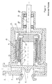
- FIG. 1 A first known pump of conventional design is shown in Figure 1 and is e.g. advertised in the brochure [1].
- a rotating pump impeller (4') is arranged, which receives the liquid to be conveyed via the suction nozzle (2 ') and ejects via the discharge nozzle (3') again under pressure.
- the radial bearing of the pump impeller (4 ') takes place by means of an impeller shaft (5') usually in plain bearings (9 ', 10'), the fixed parts in a bearing insert (11 ') are added.
- the lubrication and cooling of the plain bearings (9 ', 10') takes place by the liquid to be conveyed itself.
- the part of the rotary coupling which receives the driving torque through a partition wall, which is usually designed as a thin-walled split pot (12 '), and on the impeller shaft (5') to the pump impeller (4 ') passes, is used as a magnetic rotor ( 6 ').
- This is equipped with permanent magnets (7 '), which in turn must be surrounded before the corrosive and possibly also abrasive attack of the pumped liquid with a cylindrical protective jacket (8') liquid-tight. It should be mentioned only marginally that it may be necessary to protect an approximately metallic, that is to say ferromagnetic, magnet rotor (6 ') from corrosion as well as the shaft (5').
- the part of the rotary coupling which receives and transmits the driving torque of the motor via the drive shaft (15 ') is commonly referred to as a magnet driver (13'). He is also equipped accordingly with permanent magnets (14 '), but rotate in air and therefore are not subject to any special attack.
- the radial and axial bearing of the magnetic driver is carried out in commercial Wälzlagem (16 ').
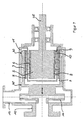
- FIG. 2 Another common embodiment, especially for smaller pumps, is shown in Figure 2. Such a pump is e.g. advertised in [2].
- a bearing insert (11 ') can be inexpensively eliminated.
- the pump impeller (4 ') is combined with the magnet rotor (6'), the permanent magnet (7 ') and the protective jacket (8') to a part.
- This rotating impeller magnetic rotor unit (19 ') is slidably mounted here on a fixed axis (17').
- the axis (17 ') itself is fastened on one side via flow ribs (18') in the suction nozzle (2 '), supported on the other side in the specially shaped containment shell (12').
- design A The design described in FIGS. 1 and 2 and largely conventional today (referred to here as design A) is characterized in that the magnet driver (13 ') is arranged radially outwardly beyond the magnet rotor (6') lying further inward.
- This construction has the advantage that the high moment of inertia of the outside magnet driver (13 ') counteracts the too rapid startup of the driving motor and thus the tearing off of the magnetic coupling can be prevented more favorably.
- this design facilitates in particular a generously axially spaced radial bearing of the pump impeller (4 '), which is always desirable due to the high hydraulic forces within the pump.
- magnetic coupling pumps with a magnet rotor (6 ') located radially on the outside, which is in contact with the liquid, and an internal magnetic driver (13') are less frequently used.
- This embodiment is referred to as type B.
- Such pumps of type B for example, in the DE 01453760 .
- EP 0171514 or EP 0171515 described and are shown in Figure 3 must be carefully designed so that the magnetic coupling does not break off during rapid startup, which threatens here due to the outside magnetic rotor (6 ').
- the radially inner magnet driver (13 ') obstructs an axially pulled-out inner sliding bearing of the impeller magnetic rotor unit (19'), if not the containment shell (12 '), with its actual opening in the type B drive side must be facing the pump, adversely wound right is executed.
- An executed pump of type B is advertised in [3] and served as a model for the figure 3.
- magnetic radial rotary joints For transmitting torques through closed walls, e.g. from Lehmann, "Characteristics and Design of Magnetic Drives", in: “Leakage-free Pumps and Compressors", publisher G. Vetter, Vulkan-Verlag Essen, 2nd edition, 1992, magnetic radial rotary joints known.
- a driving member for example a shaft, which carries magnets with alternately radially inwardly and radially outwardly directed north pole along its circumference.
- the shaft is surrounded by an abortive member, for example a hollow cylinder, which carries on its inner circumference the same number of magnets also radially alternately magnetized.
- the driving and the abortive organ can also be interchanged in their function.
- the magnets of the shaft and the hollow cylinder are coupled in pairs by attractive magnetic forces, so that upon rotation of the driving member via the magnetic coupling, the driven member is rotated.
- several smaller magnets with the same radial magnetic orientation can be arranged adjacent to one another in the axial direction.
- Non-contact permanent magnetic bearing known.
- radially magnetized magnets interact with axially magnetized magnets (EP 0 034 992 A1 ), whereby the transmittable torque is reduced, or there act axially magnetized magnet magnetized in the circumferential direction together.
- the structure described there with annular magnets is expensive.
- the invention is therefore based on the object to improve the storage of the pump impeller in a generic centrifugal pump. Another object is to provide in a generic centrifugal pump with the greatest possible magnetic coupling between the pump impeller and the driving member a wear-free or low-locking and easy and inexpensive to produce axial storage without additional components.
- a centrifugal pump is provided, are arranged in the magnets of a driving member and the pump impeller, which are arranged coaxially with axial overlap, each checkerboard with in the circumferential and axial direction alternately radially inwardly and radially outwardly directed north pole ,
- the transmission of the torque is effected by pairwise magnetic attraction, while the function of an axial bearing of the pump impeller is generated by pole change in the axial direction. It is thus created a passive magnetic and thus wear-free axial bearing of the pump impeller, which can do without components that serve only the axial storage.
- the magnets contribute to both torque transmission and axial bearing.
- the driving member of the centrifugal pump is mounted in other ways, in particular mechanically, axially, in order to pass on the axial forces there.
- the magnets carried by the organs are axially spaced apart. As a result, fastening webs can be used for easy installation.
- a partition between the organs is provided.
- two space portions of a pump or the like can be permanently and easily separated from each other hermetically without wear-affected shaft seal or the like. An escape of hazardous substances into the environment is thus reliably prevented.
- At least one organ of magnetizable material is formed, whereby the magnetic effect of the magnets can be amplified.
- a protective and / or holding device in particular in the form of a sleeve covering the respective magnets, is provided on an organ.
- a protective and / or holding device in particular in the form of a sleeve covering the respective magnets, is provided on an organ.
- the protective and / or holding device can be formed from cast or pressed molding compound, in particular from plastic. Such a protective and / or holding device is simple and inexpensive to produce by conventional means.
- a pump housing 11 has a coaxially arranged suction nozzle 12 and a radially arranged discharge nozzle 13. Between the suction nozzle 12 and the discharge nozzle 13 to a suction nozzle 12 coaxially arranged pump impeller 14 is provided which is (radially) within the pump only radially mounted, either near the axis by means of a bearing insert 41 held in the pump housing 11 small-caliber sliding bearing 39 ( Figures 5 and 6) or by means of a cup-shaped large-caliber sliding bearing 40 on the inside of the pump housing 11 ( Figures 7 and 8).
- the pump impeller 14 is rotatably driven by a drive shaft 35, which is mounted on the pump housing 11 in particular, wherein a permanent magnet non-contacting radial rotary coupling transmits the rotary drive force to the pump impeller and a partition wall 10 provided on the coupling gap 9 in the form of a known so-called split pot the drive side of the output side separates media.
- the drive shaft 35 is rotatably connected as shown in FIG. 5 and 6 with a cup-shaped drive rotor (outer member 3), while the pump impeller 14 is rotatably connected to an approximately cup-shaped output rotor (inner member 2).
- the pump impeller 14 thus forms together with a magnet (5, 6) carrying magnet rotor, here the output rotor, a structural unit (impeller magnetic rotor unit 19), which may be composed both in one piece and in many parts.
- At the inner circumference. 7 3 of the permanent magnet 5 are arranged distributed over the circumference, wherein the Polauscardi is radial and the polarities of axially adjacent and circumferentially adjacent magnets alternately - as shown in Figure 11 in principle.
- the outer magnets 5 are opposed to inner magnets 6 on the outer circumference 8 of the inner member 2, where they are suitably fixed with radial polarity alignment in the same number and arrangement as on the outer member 3.
- the polarities of axially adjacent magnets and the polarities of magnets adjacent to one another on the circumference are unlike those shown in principle in FIG. 11.
- the magnetic lines of action bridging the gap 9 are indicated as bold radial lines (FIGS. 5 to 8).
- the magnet pairings of the inner and outer members are axially opposite one another exactly when the pump impeller 14 is in its axial desired position. Since the pump impeller is only radially, namely by the inner plain bearing 39, but not axially supported, lead pressure or Saugst dealte the pump impeller to its axial deflection.
- Figure 6 is a deflection in the direction shown on the suction nozzle.
- FIGS. 9 to 16 The various possibilities of constructing the magnetic axial bearing for the pump impeller are explained in more detail with reference to the following FIGS. 9 to 16:
- the rotary radial coupling for a centrifugal pump or the like shown in FIGS. 9 and 10 comprises a driving (or optionally driven) member 2, in this case a hollow shaft which can be coupled to a motor or the like, and a driven (or optionally driving ) Organ 3, here a hollow cylinder with a front end connection for an impeller of a centrifugal pump or the like.
- the coaxially arranged members 2, 3 overlap each other axially. In the region of the axial overlap 4, each member 2, 3 carries, for example, four axially adjacent sets of radially opposite magnets 5a, 5b, 5c, 5d and 6a, 6b, 6c, 6d.
- the magnets 5 are along the inner Circumference 7 of the organ 3 is arranged, while the magnets 6 along the outer periphery 8 of the organ 2 are arranged.
- the magnets 5, 6 alternately radially inwardly and radially outwardly directed north poles, which are shown cross-hatched in the figures.
- the organs 2, 3 carry the same number, in particular equidistant magnets 5, 6, so that they are coupled in pairs by magnetic attraction and torque from the driving member 2 on the driven member 3 is transferable without slip.
- the arrangement of the magnets 6 is illustrated in FIG. 11.
- the illustrated radial magnetic radial coupling also has a noncontact passive, i. unregulated magnetic axial bearing.
- An axial restoring force counteracts due to the pole change in the axial direction of a relative axial deflection of the organs 2, 3.
- the field line profile when deflected in the axial direction is illustrated in FIG. 12.
- the axial restoring force is greater, the stronger the relative axial deflection.
- the organ 2 is thereby axially stored relative to the organ 3, in a stable equilibrium. Axial forces can be absorbed in this way.
- the arrangement shown thus represents a contactless axial bearing.
- the bearing stiffness of the axial bearing and the transferable torque between the organs 2, 3 are in the interaction as follows.
- the axial restoring force and thus the bearing stiffness increases with the number of pole changes in the axial direction per unit length.
- leakage losses also increase, so that the torque that can be transmitted between the organs 2, 3 becomes smaller.
- the transmittable torque thus increases with decreasing number of pole changes in the axial direction and also with increasing length of the magnets 5, 6 in the axial direction.
- the optimum number of axial pole changes per unit length and the optimal length of the magnets 5, 6 in the axial direction is therefore dependent on the respective requirements to determine the torque to be transmitted and the bearing stiffness, for example, empirically.
- a range between 50% and 90% of the transferable without axial pole change in the same geometry, the same magnetic mass and the same magnetic material torque is selected.
- the transmittable torque is about 80% of the torque that can be transmitted without axial pole change.
- the magnets 5, 6 are permanent magnets, but may also be electromagnets on the drive side, without thereby leaving the subject matter of the invention.
- the dimension in the axial, radial and / or circumferential direction can also vary as shown in FIG. 13 by way of example for the axial direction between the sets, so that the axial bearing and torque transmission properties can be optimally adapted to the respective requirements.
- the axial distance between axially adjacent sets of magnets 5, 6 is variable according to the requirements. Due to manufacturing reasons, not shown holding webs between the magnets 5, 6 may be provided so that they are spaced apart as shown in the axial and / or circumferential direction. However, the magnets 5, 6 can also adjoin one another in particular in the axial direction and bonded to the respective organs 2, 3, which may be wholly or partly made of magnetizable material to enhance the magnetic effect, in particular by clamping and / or otherwise fixed be connected with these. In particular, they can be held by a holding and protection device, for example, a sleeve 5 and / or 6 cross-sleeve and protected against liquids, gases or the like.
- the protective device may be formed from molded or pressed molding compound, such as plastic.
- the radial dimension of the magnets 5, 6 is chosen depending on the inner diameter of the organ 3 and the outer diameter of the organ 2 so that between radially opposite magnets 5, 6 a smallest possible gap 9 remains in the radial direction.
- a partition wall 10 shown in dashed lines may extend pot-cylindrical.
- the partition wall - also referred to as a containment shell) can separate a space area which is in contact with liquid or the like and which surrounds the driven element 3 with respect to a dry space area comprising the driving element 2, as in a centrifugal pump.
- the function of the organs 2, 3 can also be reversed, so that the organ 3 drives and the organ 2 is driven.
- the geometric shape is not limited to a hollow cylinder with hollow shaft located therein.
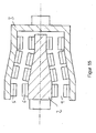
- the organs 2, 3 may also be conical, cf. It can also be provided that the organs 2, 3 conically taper between two cylindrical sections of different diameters, cf. Fig. 15.
- a step tapering portion 10 may be provided, see. Fig. 16.
- Conical, cylindrical, stepped and / or optionally other sections can be combined as desired, for example, to meet geometric specifications by the pump or to the organs 2, 3 connectable components of the pump. It is important to ensure that the axial bearing stiffness is sufficiently high, so that the organs 2, 3 or their magnets 5, 6 do not abut each other in the region of a taper.
Abstract
Description
Die Erfindung betrifft eine Kreiselpumpe mit einer permanent magnetischen berührungsfreien Radialdrehkupplung nach dem Oberbegriff des Anspruchs 1.The invention relates to a centrifugal pump with a permanent magnetic non-contacting radial rotary coupling according to the preamble of
Die Kreiselpumpen mit Magnetkupplung stellen eine wichtige Art industriell verwendeter Maschinen zur Förderung von Flüssigkeiten dar. Gegenüber den einfacheren Kreiselpumpen mit Gleitringdichtung weisen sie den Vorteil einer hermetischen Abdichtung des Pumpenraumes auf. Dies lässt sie insbesondere zur Förderung aggressiver oder giftiger Flüssigkeiten günstig erscheinen.The centrifugal pumps with magnetic coupling represent an important type of industrially used machines for the conveyance of liquids. Compared to the simpler centrifugal pumps with mechanical seal they have the advantage of a hermetic seal of the pump chamber. This makes them especially favorable for the promotion of aggressive or toxic liquids.
In den meisten ausgeführten Fällen kommen koaxiale Drehkupplungen mit radialer Anordnung der Magnete und entsprechend radialen magnetischen Wirklinien zur Anwendung. Nur diese Bauart wird im Folgenden weiter betrachtet und ist auch Gegenstand der Anmeldung.In most cases executed coaxial rotary joints with radial arrangement of the magnets and corresponding radial magnetic action lines are used. Only this type is further considered below and is also the subject of the application.
Der Hintergrund der Erfindung wird nachfolgend anhand von Figuren 1 bis 4 zu den nach dem Stand der Technik bekannten Lösungen erläutert.The background of the invention is explained below with reference to Figures 1 to 4 to the known prior art solutions.
Vorbemerkung 1: Alle Zeichnungen zeigen einen axialen Längsschnitt durch die Pumpe. Die dabei zumeist geschnittenen Rotationskörper wurden - mit der Ausnahme von Wellen - der Übersichtlichkeit halber ohne umlaufende Kanten dargestellt.Preliminary note 1: All drawings show an axial longitudinal section through the pump. The mostly cut rotational bodies were - with the exception of waves - for the sake of clarity without circumferential edges shown.
Vorbemerkung 2: Aus Gründen der Montierbarkeit und der verschiedenen verwendeten Werkstoffe muss das im nachfolgenden als Pumpengehäuse (1) bezeichnete Bauteil in der Praxis aus mehreren Teilen aufgebaut sein. Einige davon sind von der zu fördernden Flüssigkeit benetzt und müssen entsprechend abgedichtet sein, andere nicht. Aus Gründen der einfacheren Darstellung ist das Pumpengehäuse (1) hier jedoch einteilig dargestellt.Preliminary note 2: For reasons of assembly and the various materials used, the component referred to below as the pump housing (1) must in practice be made up of several parts. Some of them are wetted by the liquid to be pumped and must be sealed accordingly, others not. For the sake of simplicity of illustration, the pump housing (1) is here shown in one piece.
Eine erste bekannte Pumpe in üblicher Ausführung ist in Figur 1 dargestellt und wird z.B. in der Broschüre [1] beworben.A first known pump of conventional design is shown in Figure 1 and is e.g. advertised in the brochure [1].
Im Pumpengehäuse (1') ist ein drehendes Pumpen-Laufrad (4') angeordnet, das die zu fördernde Flüssigkeit über den Saugstutzen (2') zugeführt bekommt und über den Druckstutzen (3') wieder unter Druckaufbau auswirft.In the pump housing (1 ') a rotating pump impeller (4') is arranged, which receives the liquid to be conveyed via the suction nozzle (2 ') and ejects via the discharge nozzle (3') again under pressure.
Die radiale Lagerung des Pumpen-Laufrades (4') erfolgt vermittels einer Laufradwelle (5') üblicherweise in Gleitlagern (9', 10'), deren feststehende Teile in einem Lagereinsatz (11') aufgenommen werden. Die Schmierung und Kühlung der Gleitlager (9'; 10') erfolgt durch die zu fördemde Flüssigkeit selbst.The radial bearing of the pump impeller (4 ') takes place by means of an impeller shaft (5') usually in plain bearings (9 ', 10'), the fixed parts in a bearing insert (11 ') are added. The lubrication and cooling of the plain bearings (9 ', 10') takes place by the liquid to be conveyed itself.
Der Teil der Drehkupplung, der das antreibende Drehmoment durch eine Trennwand, die üblicherweise als dünnwandiger Spalttopf (12') ausgeführt wird, hindurch aufnimmt und über die Laufradwelle (5') an das Pumpen-Laufrad (4') weiterleitet, wird als Magnetrotor (6') bezeichnet. Dieser ist mit Permanentmagneten (7') bestückt, die wiederum vor dem korrosiven und evtl. auch abrasiven Angriff der Förderflüssigkeit mit einem zylinderförmigen Schutzmantel (8') flüssigkeitsdicht umgeben sein müssen. Es sei hier nur am Rande erwähnt, dass es erforderlich sein kann, einen etwa metallisch, sprich ferromagnetisch, ausgeführten Magnetrotor (6') auch vor Korrosion zu schützen ebenso wie die Welle (5').The part of the rotary coupling, which receives the driving torque through a partition wall, which is usually designed as a thin-walled split pot (12 '), and on the impeller shaft (5') to the pump impeller (4 ') passes, is used as a magnetic rotor ( 6 '). This is equipped with permanent magnets (7 '), which in turn must be surrounded before the corrosive and possibly also abrasive attack of the pumped liquid with a cylindrical protective jacket (8') liquid-tight. It should be mentioned only marginally that it may be necessary to protect an approximately metallic, that is to say ferromagnetic, magnet rotor (6 ') from corrosion as well as the shaft (5').
Der Teil der Drehkupplung, der das antreibende Drehmoment des Motors über die Antriebswelle (15') aufnimmt und weitergibt, wird üblich als Magnettreiber (13') bezeichnet. Auch er ist entsprechend mit Permanentmagneten (14') bestückt, die jedoch in Luft drehen und daher keinem besonderen Angriff unterliegen. Die radiale und axiale Lagerung des Magnettreibers erfolgt in handelsüblichen Wälzlagem (16').The part of the rotary coupling which receives and transmits the driving torque of the motor via the drive shaft (15 ') is commonly referred to as a magnet driver (13'). He is also equipped accordingly with permanent magnets (14 '), but rotate in air and therefore are not subject to any special attack. The radial and axial bearing of the magnetic driver is carried out in commercial Wälzlagem (16 ').
Eine weitere übliche Ausführung, insbesondere für kleinere Pumpen, zeigt Figur 2. Eine solche Pumpe wird z.B. in [2] beworben.Another common embodiment, especially for smaller pumps, is shown in Figure 2. Such a pump is e.g. advertised in [2].
Bei dieser Konstruktion kann ein Lagereinsatz (11') kostengünstig entfallen. Das Pumpen-Laufrad (4') wird mit dem Magnetrotor (6'), den Permanentmagneten (7') und dem Schutzmantel (8') zu einem Teil zusammengefasst. Diese drehende Laufrad-Magnetrotor-Einheit (19') wird hier auf einer feststehenden Achse (17') gleitend gelagert. Die Achse (17') selbst wird auf der einen Seite über Strömungsrippen (18') im Saugstutzen (2') befestigt, auf der anderen Seite in dem speziell ausgeformten Spalttopf (12') abgestützt.With this construction, a bearing insert (11 ') can be inexpensively eliminated. The pump impeller (4 ') is combined with the magnet rotor (6'), the permanent magnet (7 ') and the protective jacket (8') to a part. This rotating impeller magnetic rotor unit (19 ') is slidably mounted here on a fixed axis (17'). The axis (17 ') itself is fastened on one side via flow ribs (18') in the suction nozzle (2 '), supported on the other side in the specially shaped containment shell (12').
Die in Figur 1 und 2 beschriebene und heute weitgehend übliche Bauweise (hier als Bauart A bezeichnet) ist dadurch gekennzeichnet, dass der Magnettreiber (13') radial außen über dem weiter innen liegenden Magnetrotor (6') angeordnet ist. Diese Bauweise hat den Vorteil, dass das hohe Massenträgheitsmoment des außen gelegenen Magnettreibers (13') dem allzu schnellen Hochfahren des antreibenden Motors entgegenwirkt und somit das Abreißen der Magnetkupplung günstiger verhindert werden kann. Des Weiteren erleichtert diese Bauweise insbesondere eine großzügig axial beabstandete radiale Lagerung des Pumpen-Laufrades (4'), was aufgrund der hohen hydraulischen Kräfte innerhalb der Pumpe stets anzustreben ist.The design described in FIGS. 1 and 2 and largely conventional today (referred to here as design A) is characterized in that the magnet driver (13 ') is arranged radially outwardly beyond the magnet rotor (6') lying further inward. This construction has the advantage that the high moment of inertia of the outside magnet driver (13 ') counteracts the too rapid startup of the driving motor and thus the tearing off of the magnetic coupling can be prevented more favorably. Furthermore, this design facilitates in particular a generously axially spaced radial bearing of the pump impeller (4 '), which is always desirable due to the high hydraulic forces within the pump.
Seltener werden hingegen Magnetkupplungspumpen mit einem radial außen gelegenen Magnetrotor (6'), der ja flüssigkeitsberührt ist, und einem innen liegendem Magnetreiber (13') ausgeführt. Diese Ausführung sei als Bauart B bezeichnet.On the other hand, magnetic coupling pumps with a magnet rotor (6 ') located radially on the outside, which is in contact with the liquid, and an internal magnetic driver (13') are less frequently used. This embodiment is referred to as type B.
Solche Pumpen der Bauart B, die z.B. in der
Ein wichtiger Problembereich beim Betrieb der bisher vorgestellten Magnetpumpen, die also mit Gleitlagerungen versehen sind und das zu pumpende Medium selbst als deren Kühl- und Schmiermedium nutzen, ist das weitgehende oder völlige Ausbleiben eben dieser Flüssigkeit. Eine solche Mangelschmierung tritt dann auf, wenn sich höhere Gasanteile in der Flüssigkeit ansammeln, z.B. durch Kavitation vor der Pumpe, Trombeneintrag oder auch bei Schlürfbetrieb. Diese Gasanteile sammeln sich durch die Zentrifugalwirkung in der Pumpe in den radial innen gelegenen Hohlräumen des Pumpenkörpers an. Bei der herkömmlichen Bauweise It. Figuren 1 bis 3 befinden sich aber genau dort die Gleitlagerungen, die dann trocken fallen und dadurch häufig zerstört werden. Es sind daher viele Vorschläge gemacht worden, diesem Problem zu begegnen. Diese Lösungen bleiben jedoch oft der Tribologie der Reibpartner verhaftet - gepaart mit dem Versuch, die Reibleistung der Lager bei Mangelschmierung zu vermindern und somit die thermische Zerstörung zu vermeiden.An important problem area in the operation of the previously presented magnetic pumps, which are thus provided with sliding bearings and use the medium to be pumped itself as their cooling and lubricating medium, is the extensive or complete absence of just this liquid. Such lack of lubrication occurs when higher gas fractions accumulate in the liquid, eg by cavitation in front of the pump, Trombeneintrag or even when snoring. These gas components accumulate due to the centrifugal action in the pump in the radially inner cavities of the pump body. In the conventional construction It. Figures 1 to 3 but there are the plain bearings, which then fall dry and thereby often destroyed. Therefore, many proposals have been made to address this problem. However, these solutions often remain the tribology of the friction partners arrested - coupled with the attempt to reduce the friction of the bearing in case of deficient lubrication and thus to avoid the thermal destruction.
Einen technisch anderen und sehr sinnvollen Weg, nämlich die gefährdete Gleitlagerung radial möglichst weit nach außen zu verlegen, weist der Lösungsansatz einer "wellenlosen" Magnetpumpe wie in [4] beschrieben auf, welcher in Figur 4 dargestellt ist. Diese Konstruktion ist der Bauart A zuzuordnen. Es gelingt hier zu einer wellen- und achsenlosen Konstruktion zu gelangen, indem als feststehender Teil (10') der Gleitlagerung ein Abschnitt des Spalttopfes (12') verwendet wird und der rotierende Teil (9') der Gleitlagerung durch einen Abschnitt des Schutzmantels (8') gebildet wird. Das Pumpen-Laufrad (4') wird mit dem Magnetrotor (6'), den Permanentmagneten (7') und dem Schutzmantel (8') zu einem hohlen Laufrad-Magnetrotor-Einheit (19') verbunden.A technically different and very sensible way, namely to move the endangered plain bearing radially as far as possible to the outside, has the approach of a "shaftless" magnetic pump as described in [4], which is shown in Figure 4. This construction is assigned to type A. It succeeds here to achieve a shaft and axle-less construction by a fixed portion (10 ') of the sliding bearing a portion of the gap pot (12') is used and the rotating part (9 ') of the sliding bearing by a portion of the protective jacket (8 ') is formed. The pump impeller (4 ') is connected to the magnet rotor (6'), the permanent magnet (7 ') and the protective jacket (8') to a hollow impeller magnetic rotor unit (19 ').
Dennoch bleibt der Vorschlag aus [4] technisch beschränkt. So findet die radiale Gleitlagerung der Laufrad-Magnetrotor-Einheit (19') im Spalttopf (12') selbst statt, der aber gerade an dieser Stelle als sehr dünnwandiges Bauteil ausgeführt werden muss. Darauf wird auch in [4] hingewiesen und es kann dort daher auch nicht auf stabilere zusätzliche Anfahr- bzw. Notlager (37') verzichtet werden, die nachteilig teils immer noch durch den Spalttopf (12') gebildet werden müssen. Weiterhin gestattet die Abstützung der Lagerung im dünnwandigen Spalttopf keine äußere Kühlung oder einen einfachen äußeren Zugang, etwa zur Lagertemperaturüberwachung oder zur Zwangsspülung.Nevertheless, the proposal from [4] remains technically limited. Thus, the radial slide bearing of the impeller magnetic rotor unit (19 ') takes place in the containment shell (12') itself, which, however, has to be executed at this point as a very thin-walled component. This is also pointed out in [4] and it is therefore not possible to dispense with more stable additional start-up or emergency bearings (37 ') which, disadvantageously, still partly have to be formed by the containment shell (12'). Furthermore, the support of the storage in thin-walled containment shell does not allow external cooling or easy external access, such as storage temperature monitoring or forced flushing.
Es bleibt festzustellen, dass im Falle einer Betriebsstörung, z.B. bei Kavitation vor der Pumpe, Trombeneintrag oder auch bei Schlürfbetrieb, eine Kreiselpumpe mit deutlich erhöhten Gasanteilen in der zu fördernden Flüssigkeit beaufschlagt wird. Diese Gasanteile sammeln sich durch die Zentrifugalwirkung in der Pumpe in den radial innen gelegenen Hohlräumen des Pumpenkörpers an. Bei herkömmlich ausgeführten Magnetkupplungspumpen befinden sich dort die Gleitlagerungen, die dann trocken fallen und dadurch häufig zerstört werden.It should be noted that in the case of a malfunction, eg cavitation in front of the pump, Trombeneintrag or even in Schlürfbetrieb, a centrifugal pump with significantly increased gas fractions is applied in the liquid to be delivered. These gas components accumulate due to the centrifugal action in the pump in the radially inner cavities of the pump body. In conventionally designed magnetic drive pumps there are the sliding bearings, which then fall dry and are therefore often destroyed.
Zur Übertragung von Drehmomenten durch geschlossene Wandungen hindurch sind z.B. aus Lehmann, "Eigenschaften und Auslegung von Magnetantrieben", in: "Leckagefreie Pumpen und Verdichter", Herausgeber G. Vetter, Vulkan-Verlag Essen, 2. Auflage, 1992, magnetische Radialdrehkupplungen bekannt. Diese umfassen ein antreibendes Organ, beispielsweise eine Welle, die entlang ihres Umfangs gleichverteilt Magnete mit abwechselnd radial einwärts und radial auswärts gerichtetem Nordpol trägt. Die Welle ist von einem abtreibenden Organ, beispielsweise einem Hohlzylinder, umgeben, der an seinem Innenumfang dieselbe Anzahl von ebenfalls radial abwechselnd magnetisierten Magneten trägt. Das antreibende und das abtreibende Organ können in ihrer Funktion auch vertauscht werden. Die Magnete der Welle und des Hohlzylinders sind paarweise durch anziehende Magnetkräfte gekoppelt, so dass bei Drehung des antreibenden Organs über die Magnetkopplung das angetriebene Organ mitgedreht wird. Hierbei können aus produktionstechnischen Gründen in Axialrichtung mehrere kleinere Magnete mit gleicher radialer magnetischer Ausrichtung benachbart zueinander angeordnet sein.For transmitting torques through closed walls, e.g. from Lehmann, "Characteristics and Design of Magnetic Drives", in: "Leakage-free Pumps and Compressors", publisher G. Vetter, Vulkan-Verlag Essen, 2nd edition, 1992, magnetic radial rotary joints known. These comprise a driving member, for example a shaft, which carries magnets with alternately radially inwardly and radially outwardly directed north pole along its circumference. The shaft is surrounded by an abortive member, for example a hollow cylinder, which carries on its inner circumference the same number of magnets also radially alternately magnetized. The driving and the abortive organ can also be interchanged in their function. The magnets of the shaft and the hollow cylinder are coupled in pairs by attractive magnetic forces, so that upon rotation of the driving member via the magnetic coupling, the driven member is rotated. For reasons of production technology, several smaller magnets with the same radial magnetic orientation can be arranged adjacent to one another in the axial direction.
Zwar sind aus den
Der Erfindung liegt daher die Aufgabe zugrunde, bei einer gattungsgemäßen Kreiselpumpe die Lagerung des Pumpen-Laufrades zu verbessern. Ein weiteres Ziel besteht darin, bei einer gattungsgemäßen Kreiselpumpe bei größtmöglicher magnetischer Kopplung zwischen dem Pumpen-Laufrad und dem antreibenden Organ eine verschleißfreie oder besonders verschließarme sowie einfach und kostengünstig herstellbare axiale Lagerung ohne zusätzliche Komponenten zu schaffen.The invention is therefore based on the object to improve the storage of the pump impeller in a generic centrifugal pump. Another object is to provide in a generic centrifugal pump with the greatest possible magnetic coupling between the pump impeller and the driving member a wear-free or low-locking and easy and inexpensive to produce axial storage without additional components.
Diese Aufgabe wird entsprechend den Merkmalen des Anspruchs 1 gelöst.This object is achieved according to the features of
Durch die Lösung nach Anspruch 1 wird eine Kreiselpumpe geschaffen, bei der Magnete von einem antreibenden Organ und dem Pumpen-Laufrad, die koaxial mit axialer Überlappung angeordnet sind, jeweils schachbrettartig mit in Umfangs- und Axialrichtung abwechselnd radial einwärts und radial auswärts gerichtetem Nordpol angeordnet sind. Die Übertragung des Drehmoments erfolgt durch paarweise magnetische Anziehung, während die Funktion einer axialen Lagerung des Pumpen-Laufrades durch Polwechsel in axialer Richtung erzeugt wird. Es wird so eine passive magnetische und damit verschleißfreie axiale Lagerung des Pumpen-Laufrades geschaffen, die ohne Komponenten, die nur der axialen Lagerung dienen, auskommen kann. Die Magnete tragen sowohl zur Übertragung des Drehmoments als auch zur axialen Lagerung bei. Das antreibende Organ der Kreiselpumpe wird auf andere Weise, insbesondere mechanisch, axial gelagert, um dort die axialen Kräfte weiterzugeben.The solution according to
Günstig und den Effekt der axialen Steifigkeit noch verstärkend wirkt sich eine möglichst häufige Abwechslung der Polung pro Längeneinheit in axialer Richtung aus. Mit steigender Anzahl an Polwechseln ergeben sich durch Streuverluste jedoch auch immer kleinere übertragbare Drehmomente, was der Konstrukteur berücksichtigen muss. Das übertragbare Drehmoment und die Lagersteifigkeit stehen dabei in Wechselwirkung derart, dass ein höheres Drehmoment eine geringere Lagersteifigkeit bedingt und umgekehrt. Ein besonders wichtiger Bereich einer Konstruktion nach dieser neuartigen technischen Lehre ist daher ein Bereich, der bei gleicher Geometrie, gleicher Magnetmasse und gleichem Magnetwerkstoff wie bei der Anordnung nach Stand der Technik immer noch ein übertragbares Drehmoment zwischen 90% und 50% des maximal erreichbaren bewirkt. Dieser Bereich hat sich als optimal herausgestellt.Favorable and the effect of the axial stiffness still reinforcing a most frequent alternation of polarity per unit length in the axial direction. However, as the number of pole changes increases, scattering losses also result in ever smaller transmittable torques, which the designer must take into account. The transmissible torque and the bearing stiffness are interacting in such a way that a higher torque causes a lower bearing stiffness and vice versa. A particularly important area of a construction according to this novel technical teaching is therefore an area which, given the same geometry, has the same magnetic mass and the same magnetic material as in the prior art arrangement still causes a transmittable torque between 90% and 50% of the maximum achievable. This area has turned out to be optimal.
Zweckmäßigerweise sind die von den Organen getragenen Magnete axial voneinander beabstandet. Hierdurch können Befestigungsstege für eine einfache Montage verwendet werden.Conveniently, the magnets carried by the organs are axially spaced apart. As a result, fastening webs can be used for easy installation.
Vorzugsweise ist eine Trennwand zwischen den Organen vorgesehen. Hierdurch können zwei Raumbereiche einer Pumpe oder dgl. hermetisch ohne verschleißbehaftete Wellendichtung oder dgl. dauerhaft und einfach voneinander getrennt werden. Ein Austritt Gefahr bringender Substanzen in die Umwelt wird damit sicher unterbunden.Preferably, a partition between the organs is provided. As a result, two space portions of a pump or the like can be permanently and easily separated from each other hermetically without wear-affected shaft seal or the like. An escape of hazardous substances into the environment is thus reliably prevented.
Es ist sinnvoll, dass alle Magnete eines Organs dieselbe Geometrie haben. Hierdurch entfallen Produktions- und Vorhaltekosten für verschieden große Magnete. Zudem wird die Montage vereinfacht, da nicht zwischen verschiedenen Magneten unterschieden werden muss. Insgesamt ist die Radialdrehkupplung damit kostengünstiger herstellbar.It makes sense that all magnets of an organ have the same geometry. This eliminates production and storage costs for different sized magnets. In addition, the assembly is simplified because it does not have to distinguish between different magnets. Overall, the radial rotary coupling is thus less expensive to produce.
Zweckmäßigerweise ist mindestens ein Organ aus magnetisierbarem Material gebildet, wodurch die magnetische Wirkung der Magnete verstärkbar ist.Conveniently, at least one organ of magnetizable material is formed, whereby the magnetic effect of the magnets can be amplified.
Gegebenenfalls ist an einem Organ eine Schutz- und/oder Haltevorrichtung insbesondere in Form einer die jeweiligen Magnete überdeckenden Hülse vorgesehen. Hierdurch kann ein Kontakt mit beispielsweise korrodierender Flüssigkeit unterbunden werden, wodurch die Magnete und deren Befestigung keiner Abnutzung unterliegen. Zudem ist ein sicherer Halt der Magnete am Organ gewährleistet und ein Ablösen eines Magnets, das zur Blockade der Kreiselpumpe führen kann, wird verhindert.Optionally, a protective and / or holding device, in particular in the form of a sleeve covering the respective magnets, is provided on an organ. As a result, contact with, for example, corrosive liquid can be prevented, whereby the magnets and their attachment are not subject to wear. In addition, a secure hold of the magnets is ensured on the organ and a detachment of a magnet, which can lead to the blockage of the centrifugal pump is prevented.
Die Schutz- und/oder Haltevorrichtung kann aus gegossener oder gepresster Formmasse, insbesondere aus Kunststoff, gebildet sein. Eine derartige Schutz- und/oder Haltevorrichtung ist einfach und kostengünstig mit üblichen Mitteln herstellbar.The protective and / or holding device can be formed from cast or pressed molding compound, in particular from plastic. Such a protective and / or holding device is simple and inexpensive to produce by conventional means.
Die vorgenannten sowie die beanspruchten und die in den Ausführungsbeispielen beschriebenen erfindungsgemäß zu verwendenden Bauteile unterliegen in ihrer Größe, Formgestaltung, Materialauswahl und technischen Konzeption keinen besonderen Ausnahmebedingungen, so dass die in dem Anwendungsgebiet bekannten Auswahlkriterien uneingeschränkt Anwendung finden können.The above-mentioned as well as the claimed and described in the embodiments described components to be used are subject to their size, shape design, choice of materials and technical design no special conditions of exception, so that the well-known in the field of application selection criteria can apply without restriction.
Weitere Einzelheiten, Merkmale und Vorteile des Gegenstands der Erfindung ergeben sich aus den Unteransprüchen sowie aus der nachfolgenden Beschreibung.Further details, features and advantages of the subject of the invention will become apparent from the dependent claims and from the following description.
Die Erfindung wird nachstehend anhand von in den beigefügten Abbildungen schematisiert dargestellten Ausführungsbeispielen näher erläutert.The invention will be explained in more detail below with reference to exemplary embodiments illustrated diagrammatically in the attached figures.
- Fig. 1 bis 4 zeigen aus dem Stand der Technik bekannte Pumpen.Figs. 1 to 4 show known from the prior art pumps.
- Fig. 5 zeigt eine erste Ausführungsform einer erfindungsgemäßen Kreiselpumpe im Axialschnitt - schematisiert.Fig. 5 shows a first embodiment of a centrifugal pump according to the invention in axial section - schematized.
- Fig. 6 zeigt dieselbe Kreiselpumpe in einer axial ausgelenkten Position des Pumpen-Laufrades.Fig. 6 shows the same centrifugal pump in an axially deflected position of the pump impeller.
- Fig. 7 zeigt eine zweite Ausführungsform einer Kreiselpumpe im Axialschnitt - schematisiert.Fig. 7 shows a second embodiment of a centrifugal pump in axial section - schematized.
- Fig. 8 zeigt dieselbe Kreiselpumpe in einer axial ausgelenkten Stellung des Pumpen-Laufrades.Fig. 8 shows the same centrifugal pump in an axially deflected position of the pump impeller.
- Fig. 9 zeigt von einer Kreiselpumpe eine passiv magnetisch axial gelagerte magnetische Radialdrehkupplung im Längsschnitt.Fig. 9 shows a centrifugal pump a passively axially axially mounted magnetic radial rotary coupling in longitudinal section.
- Fig. 10 zeigt von einer Kreiselpumpe die Radialdrehkupplung der Fig. 9 im Querschnitt entlang der Linie A-A.Fig. 10 shows a rotary pump of the radial rotary coupling of Fig. 9 in cross section along the line A-A.
- Fig. 11 zeigt eine perspektivische Ansicht der Organe ähnlich Fig. 9, jedoch mit einer größeren Anzahl von Magneten sowohl in Umfangsrichtung als auch in axialer Richtung.Fig. 11 shows a perspective view of the organs similar to Fig. 9, but with a larger number of magnets in both the circumferential direction and in the axial direction.
- Fig.12 illustriert den Feldlinienverlauf bei dynamischer Auslenkung in axialer Richtung der Radialdrehkupplung nach Fig. 9.12 illustrates the field line profile with dynamic deflection in the axial direction of the radial rotational coupling according to FIG. 9.
- Fig. 13 zeigt von einer Kreiselpumpe eine weitere passiv magnetisch axial gelagerte magnetische Radialdrehkupplung im Längsschnitt.Fig. 13 shows a centrifugal pump, a further passive magnetic axially mounted magnetic radial rotary coupling in longitudinal section.
- Fig. 14, 15 und 16 zeigen von einer Kreiselpumpe jeweils weitere passiv magnetisch gelagerte magnetische Radialdrehkupplungen im Längsschnitt.FIGS. 14, 15 and 16 show, in longitudinal section, further passively magnetically mounted magnetic radial rotary joints of a centrifugal pump.
Bei den Ausführungsformen nach Figuren 5 bis 8 weist ein Pumpengehäuse 11 einen koaxial angeordneten Saugstutzen 12 und einen radial angeordneten Druckstutzen 13 auf. Zwischen dem Saugstutzen 12 und dem Druckstutzen 13 ist ein zum Saugstutzen 12 koaxial angeordnetes Pumpen-Laufrad 14 vorgesehen, welches (mechanisch) innerhalb der Pumpe lediglich radial gelagert ist, und zwar entweder achsnah mittels eines von einem Lagereinsatz 41 im Pumpengehäuse 11 gehaltenen kleinkalibrigen Gleitlagers 39 (Figuren 5 und 6) oder mittels eines topfförmigen großkalibrigen Gleitlagers 40 an der Innenseite des Pumpengehäuses 11 (Figuren 7 und 8). Das Pumpenlaufrad 14 wird durch eine indirekt am Pumpengehäuse 11 insbesondere wälzgelagerte Antriebswelle 35 drehangetrieben, wobei eine permanentmagnetische berührungsfreie Radialdrehkupplung die Drehantriebskraft auf das Pumpen-Laufrad überträgt und eine an dem Kupplungsspalt 9 vorgesehene Trennwand 10 in Form eines an sich bekannten so genannten Spalttopfes die Antriebsseite von der Abtriebsseite medienmäßig trennt.In the embodiments of Figures 5 to 8, a
Die Antriebswelle 35 ist gemäß Fig. 5 und 6 mit einem topfförmigen Antriebsrotor (äußeres Organ 3) drehfest verbunden, während das Pumpen-Laufrad 14 mit einem etwa topfförmigen Abtriebsrotor (inneres Organ 2) drehfest verbunden ist. (Das Pumpen-Laufrad 14 bildet also zusammen mit einem Magnete (5, 6) tragenden Magnetrotor, hier dem Abtriebsrotor, eine Baueinheit (Laufrad-Magnetrotor-Einheit 19), die sowohl einteilig als auch vielteilig zusammengesetzt sein kann.) Am inneren Umfang 7 des Organs 3 sind Permanentmagnete 5 über den Umfang verteilt angeordnet, wobei die Polausrichtung radial ist und sich die Polungen axial benachbarter und umfangsmäßig benachbarter Magnete jeweils abwechseln - wie aus Figur 11 prinzipiell ersichtlich. Den äußeren Magneten 5 stehen innere Magnete 6 am äußeren Umfang 8 des inneren Organs 2 gegenüber, wo sie mit radialer Polungsausrichtung in gleicher Stückzahl und Anordnung wie am äußeren Organ 3 geeignet befestigt sind. Auch hier sind die Polungen axial benachbarter Magnete und die Polungen von auf einem Umfang benachbarten Magneten ungleichnamig wie in Figur 11 prinzipiell dargestellt. Zwischen den Nordpolen (kreuzschraffiert) und den Südpolen (einfachschraffiert) sind die den Spalt 9 überbrückenden Magnetwirklinien als fette radiale Striche angedeutet (Fig. 5 bis 8).The
Wie aus Figur 5 ersichtlich, stehen sich die Magnetpaarungen des inneren und äußeren Organs - axial - genau gegenüber, wenn sich das Pumpenlaufrad 14 in seiner axialen Solllage befindet. Da das Pumpenlaufrad lediglich radial, nämlich durch das innen liegende Gleitlager 39, nicht aber axial gelagert ist, führen Druck- oder Saugstöße am Pumpenlaufrad zu dessen axialer Auslenkung. In Figur 6 ist eine Auslenkung in Richtung auf den Saugstutzen dargestellt. In Folge dieser axialen Auslenkung bilden sich an den gegenüberstehenden Magnetpaarungen des äußeren und inneren Organs axial gerichtete magnetische Richtkräfte aus, die durch Schrägstellen der Wirklinien zeichnerisch angedeutet sind und die jeweils im Sinne einer Rückstellung des Pumpenlaufrades auf die in Figur 5 dargestellte Solllage orientiert sind. - Entsprechendes gilt für das Ausführungsbeispiel nach Figuren 7 und 8, wobei das äußere Organ 3 bei diesem Ausführungsbeispiel mit dem Pumpenlaufrad und das innere Organ 2 mit der Antriebswelle 35 drehfest verbunden ist. Es versteht sich, dass in beiden Ausführungsbeispielen davon ausgegangen wird, dass die axiale Beweglichkeit der Antriebswelle 35 im Vergleich zur axialen Beweglichkeit des Pumpenlaufrades 14 durch Vorsehen entsprechender und an sich bekannter Axiallager für die Antriebswelle eingeschränkt ist.As can be seen from FIG. 5, the magnet pairings of the inner and outer members are axially opposite one another exactly when the
Bei dem Ausführungsbeispiel nach Figuren 7 und 8 ergibt sich der besondere Vorteil, dass die Gleitlagerung 40 des Pumpenlaufrades 14 den maximal möglichen Wirkdurchmesser hat und daher die Gleitung besonders gut ist. Außerdem ist hier die Trockenlaufeigenschaft der Pumpe erheblich verbessert, weil selbst geringe Restmengen an Pumpfilüssigkeit das gehäuseseitige Gleitlager 40 ausreichend kühlen und auch über die Pumpengehäusewand eine zusätzliche Lagerkühlung erfolgt.In the embodiment of Figures 7 and 8, there is the particular advantage that the sliding
Die verschiedenen Möglichkeiten des Aufbaus der magnetischen Axiallagerung für das Pumpenlaufrad sind anhand der folgenden Figuren 9 bis 16 näher erläutert:The various possibilities of constructing the magnetic axial bearing for the pump impeller are explained in more detail with reference to the following FIGS. 9 to 16:
Die in Fig. 9 und 10 dargestellte Radialdrehkupplung für eine Kreiselpumpe oder dgl. umfasst ein antreibendes (oder - wahlweise - angetriebenes) Organ 2, hier eine stimseitig an einen Motor od. dgl. koppelbare Hohlwelle, und ein angetriebenes (oder - wahlweise - antreibendes) Organ 3, hier ein Hohlzylinder mit einem stimseitigen Anschluss für ein Laufrad einer Kreiselpumpe oder dgl. Die koaxial angeordneten Organe 2, 3 überlappen einander axial. Im Bereich der axialen Überlappung 4 trägt jedes Organ 2, 3 beispielsweise vier axial benachbarte Sätze einander radial gegenüberliegender Magnete 5a, 5b, 5c, 5d bzw. 6a, 6b, 6c, 6d. Die Magnete 5 sind dabei entlang des inneren Umfangs 7 des Organs 3 angeordnet, während die Magnete 6 entlang des äußeren Umfangs 8 des Organs 2 angeordnet sind. Entlang des jeweiligen Umfangs 7, 8 und in axialer Richtung weisen die Magnete 5, 6 abwechselnd radial einwärts und radial auswärts gerichtete Nordpole auf, die in den Fig. kreuzschraffiert dargestellt sind. Zweckmäßigerweise tragen die Organe 2, 3 dieselbe Anzahl insbesondere gleich beabstandeter Magnete 5, 6, so dass diese paarweise durch magnetische Anziehungskraft gekoppelt sind und ein Drehmoment vom antreibenden Organ 2 auf das angetriebene Organ 3 schlupffrei übertragbar ist. Die Anordnung der Magnete 6 ist in Fig. 11 veranschaulicht.The rotary radial coupling for a centrifugal pump or the like shown in FIGS. 9 and 10 comprises a driving (or optionally driven)
Die dargestellte magnetische Radialdrehkupplung weist zudem eine berührungslose passive, d.h. regelungslose, magnetische axiale Lagerung auf. Eine axiale Rückstellkraft wirkt infolge der Polwechsel in axialer Richtung einer relativen axialen Auslenkung der Organe 2, 3 entgegen. Der Feldlinienverlauf bei Auslenkung in axialer Richtung ist in Fig. 12 illustriert. Die axiale Rückstellkraft ist umso größer, je stärker die relative axiale Auslenkung ist. Das Organ 2 ist dadurch axial relativ zum Organ 3 gelagert, und zwar in einem stabilen Gleichgewicht. Axialkräfte können so aufgenommen werden. Die dargestellte Anordnung stellt damit eine berührungslose axiale Lagerung dar.The illustrated radial magnetic radial coupling also has a noncontact passive, i. unregulated magnetic axial bearing. An axial restoring force counteracts due to the pole change in the axial direction of a relative axial deflection of the
Die Lagersteifigkeit der axialen Lagerung und das zwischen den Organen 2, 3 übertragbare Drehmoment stehen dabei wie folgt in Wechselwirkung. Die axiale Rückstellkraft und somit die Lagersteifigkeit steigt mit der Anzahl der Polwechsel in Axialrichtung pro Längeneinheit. Mit steigender Anzahl von Polwechseln erhöhen sich jedoch auch Streuverluste, so dass das zwischen den Organen 2, 3 übertragbare Drehmoment kleiner wird. Das übertragbare Drehmoment steigt also mit abnehmender Anzahl von Polwechseln in Axialrichtung und zudem mit steigender Länge der Magnete 5, 6 in Axialrichtung.The bearing stiffness of the axial bearing and the transferable torque between the
Die optimale Anzahl von axialen Polwechseln pro Längeneinheit und die optimale Länge der Magnete 5, 6 in Axialrichtung ist daher abhängig von den jeweiligen Anforderungen an die zu übertragenden Drehmomente und die Lagersteifigkeit beispielsweise empirisch zu ermitteln. Vorteilhafterweise wird ein Bereich zwischen 50% und 90% des ohne axialen Polwechsel bei gleicher Geometrie, gleicher Magnetmasse und gleichem Magnetwerkstoff übertragbaren Drehmoments gewählt. In dem in Fig. 9 dargestellten Beispiel beträgt das übertragbare Drehmoment etwa 80% des ohne axialen Polwechsel übertragbaren Drehmoments.The optimum number of axial pole changes per unit length and the optimal length of the
Die Magnete 5, 6 sind Permanentmagnete, können antriebsseitig ggf. aber auch Elektromagnete sein, ohne dass dadurch der Gegenstand der Erfindung verlassen wird. Aus Kostengründen sind die Magnete 5 bzw. 6, wie in Fig. 9 bis 12 dargestellt, vorzugsweise jeweils von gleicher Geometrie. Die Dimension in Axial-, Radial- und/oder Umfangsrichtung kann jedoch auch wie in Fig. 13 beispielhaft für die Axialrichtung dargestellt zwischen den Sätzen variieren, damit die Axiallager- und Drehmomentübertragungseigenschaften optimal an die jeweiligen Anforderungen anpassbar sind.The
Der axiale Abstand zwischen axial benachbarten Sätzen von Magneten 5, 6 ist entsprechend den Anforderungen variierbar. Herstellungsbedingt können nicht dargestellte Haltestege zwischen den Magneten 5, 6 vorgesehen sein, so dass diese wie dargestellt in Axial- und/oder Umfangsrichtung voneinander beabstandet sind. Die Magnete 5, 6 können jedoch auch insbesondere in Axialrichtung aneinander angrenzen und mit den jeweiligen Organen 2, 3, die zur Verstärkung der magnetischen Wirkung ganz oder teilweise aus magnetisierbarem Material gebildet sein können, verklebt, in diese insbesondere klemmend eingesetzt und/oder anderweitig fest mit diesen verbunden sein. Insbesondere können sie von einer Halte- und Schutzvorrichtung, beispielsweise einer die Magnete 5 und/oder 6 übergreifenden Hülse gehalten und vor Flüssigkeiten, Gasen oder dgl. geschützt werden. Die Schutzvorrichtung kann aus gegossener oder gepresster Formmasse wie etwa Kunststoff gebildet sein.The axial distance between axially adjacent sets of
Die radiale Dimension der Magnete 5, 6 wird in Abhängigkeit des Innendurchmessers des Organs 3 und des Außendurchmessers des Organs 2 so gewählt, dass zwischen einander radial gegenüberliegenden Magneten 5, 6 ein möglichst kleiner Spalt 9 in radialer Richtung verbleibt. Durch den Spalt 9 und entlang des Bodens des hier hohlzylinderförmigen Organs 3 kann sich eine gestrichelt angedeutet dargestellte Trennwand 10 (Fig. 9) topfzylinderförmig erstrecken. Die Trennwand - auch als Spalttopf bezeichnet) kann einen mit Flüssigkeit oder dgl. in Berührung kommenden, das angetriebene Organ 3 umfassenden Raumbereich gegenüber einem trockenen und das antreibende Organ 2 umfassenden Raumbereich abtrennen, wie in einer Kreiselpumpe.The radial dimension of the
Die Funktion der Organe 2, 3 kann auch vertauscht sein, so dass das Organ 3 antreibt und das Organ 2 angetrieben wird. Zudem ist die geometrische Form nicht auf einen Hohlzylinder mit darin befindlicher Hohlwelle beschränkt. Beispielsweise können die Organe 2, 3 auch kegelig ausgebildet sein, vgl. Fig. 14. Es kann auch vorgesehen sein, dass sich die Organe 2, 3 zwischen zwei zylindrischen Abschnitten mit verschiedenen Durchmessern konisch verjüngen, vgl. Fig. 15. Gegebenenfalls kann ein sich stufig verjüngender Abschnitt 10 vorgesehen sein, vgl. Fig. 16. Konische, zylindrische, stufige und/oder gegebenenfalls weitere Abschnitte können beliebig kombiniert werden, um beispielsweise geometrische Vorgaben durch die Pumpe oder an die Organe 2, 3 anschließbare Komponenten der Pumpe zu erfüllen. Hierbei ist darauf zu achten, dass die axiale Lagersteifigkeit ausreichend hoch ist, damit die Organe 2, 3 bzw. deren Magnete 5, 6 im Bereich einer Verjüngung nicht aneinander stoßen.The function of the
- 11
- Kreiselpumperotary pump
- 22
- inneres Organinternal organ
- 33
- äußeres Organexternal organ
- 44
- axiale Überlappungaxial overlap
- 55
- äußere Magneteouter magnets
- 5a-d5a-d
- Magnetemagnets
- 66
- innere Magneteinner magnets
- 6a-d6a-d
- Magnetemagnets
- 77
- innerer Umfanginner circumference
- 88th
- äußerer Umfangouter circumference
- 99
- Spaltgap
- 1010
- Trennwandpartition wall
- 1111
- Pumpengehäusepump housing
- 1212
- Saugstutzensuction
- 1313
- Druckstutzenpressure port
- 1414
- Pumpenlaufradpump impeller
- 1515
- Laufradwelleimpeller shaft
- 1919
- Laufrad-Magnetrotor-EinheitImpeller-magnetic rotor unit
- 3535
- Antriebswelledrive shaft
- 3939
- Gleitlagerbearings
- 4040
- Gleitlagerbearings
- 4141
- Lagereinsatzbearing insert
-
[1]
Broschüre der Firma WERNERT-PUMPEN GMBH D-45476 Mülheim an der Ruhr Chemienormpumpe aus Kunststoff mit Magnetkupplung - Typenreihe NM Ausgabe 687/02
Brochure of the company WERNERT-PUMPEN GMBH D-45476 Mülheim an der Ruhr Standardized chemical plastic pump with magnetic coupling - Type series NM Edition 687/02 -
[2]
Broschüre der Firma IWAKI Pumpen Iwaki magnetgetriebene Pumpen - Serie MDM printed in Japan 99.11.ITN
IWAKI Pumps brochure Iwaki solenoid driven pumps - MDM printed series in Japan 99.11.ITN -
[3]
Broschüre der Firma CP-Pumpen AG CH-4800 Zofingen: Magnetkupplungspumpe MKP, metallisch
Brochure of the company CP-Pumpen AG CH-4800 Zofingen: Magnetic coupling pump MKP, metallic -
[4]
Robert Neumaier: Hermetische Pumpen Verlag und Bildarchiv W.H. Faragallah, 1994 ISBN-3-929682-05-2 Kapitel 3.7.12 Wellenlose Magnetkupplungs-Kreiselpumpen S. 356 ff
Robert Neumaier: Hermetic pumps Verlag und Bildarchiv WH Faragallah, 1994 ISBN-3-929682-05-2 Chapter 3.7.12 Wave-less magnetic-coupling centrifugal pumps p. 356 ff
Claims (9)
zur axialen Lagerung der Laufrad-Magnetrotor-Einheit. (19) die Drehkupplung dient, wobei
axial benachbarte Magnete (5a, 5b; 6a, 6b) am radial inneren sowie am radial äußeren Organ (2, 3) jeweils radial entgegengesetzt ausgerichtete Nordpole aufweisen und die Polwechsel in Axialrichtung eine berührungslos wirkende passive axiale Lagerung zur Aufnahme von Axialkräften zwischen den Organen (2, 3) bilden.rotary pump
for axially supporting the impeller magnetic rotor unit. (19) the rotary coupling is used, wherein
axially adjacent magnets (5a, 5b; 6a, 6b) on the radially inner and on the radially outer member (2, 3) each have radially oppositely directed north poles and the pole changes in the axial direction of a non-contact passive axial bearing for receiving axial forces between the organs ( 2, 3) form.
Applications Claiming Priority (2)
| Application Number | Priority Date | Filing Date | Title |
|---|---|---|---|
| DE200520020288 DE202005020288U1 (en) | 2005-12-23 | 2005-12-23 | Permanent magnet contactless radial rotary coupler for e.g. vertical pump, has magnets polarized equally in circumferential direction, where magnets form non-contact operating passive radial support for receiving radial forces between units |
| DE202006005189U DE202006005189U1 (en) | 2006-03-31 | 2006-03-31 | Centrifugal pump with coaxial magnetic coupling |
Publications (2)
| Publication Number | Publication Date |
|---|---|
| EP1801420A2 true EP1801420A2 (en) | 2007-06-27 |
| EP1801420A3 EP1801420A3 (en) | 2009-10-21 |
Family
ID=37600791
Family Applications (1)
| Application Number | Title | Priority Date | Filing Date |
|---|---|---|---|
| EP06026728A Withdrawn EP1801420A3 (en) | 2005-12-23 | 2006-12-22 | Centrifugal pump with magnetic coupling |
Country Status (2)
| Country | Link |
|---|---|
| EP (1) | EP1801420A3 (en) |
| DE (1) | DE102006062170A1 (en) |
Cited By (15)
| Publication number | Priority date | Publication date | Assignee | Title |
|---|---|---|---|---|
| EP2055910A1 (en) * | 2006-12-27 | 2009-05-06 | Toyota Jidosha Kabushiki Kaisha | Water pump |
| DE202011106968U1 (en) | 2011-10-19 | 2012-02-28 | Bernd Lohse | Magnet rotor system |
| CN101855008B (en) * | 2007-11-12 | 2013-04-17 | 艾卡工厂有限及两合公司 | Rotor-stator-device for dispersing or homogenizing |
| AT512841A1 (en) * | 2013-08-08 | 2013-11-15 | Avl List Gmbh | Non-contact magnetic coupling |
| US20150069872A1 (en) * | 2013-09-06 | 2015-03-12 | Delta Electronics (Shanghai) Co., Ltd. | Cylindrical permanent magnetic coupling device |
| WO2016018766A1 (en) * | 2014-07-29 | 2016-02-04 | Magnadrive Corporation | Magnetic clutch systems and methods |
| EP3091647A1 (en) * | 2015-04-28 | 2016-11-09 | PRG Präzisions-Rührer GmbH | Drive unit for an agitator and an agitator |
| EP3306099A1 (en) * | 2016-12-23 | 2018-04-11 | C.D.R. Pompe S.r.l. | Magnetic drive pump |
| WO2018185961A1 (en) * | 2017-04-03 | 2018-10-11 | 株式会社Ihi | Pump for rocket fuel |
| WO2019219884A1 (en) * | 2018-05-16 | 2019-11-21 | Kardion Gmbh | Megnetic coupling for contactless torque transmission |
| US11368081B2 (en) | 2018-01-24 | 2022-06-21 | Kardion Gmbh | Magnetic coupling element with a magnetic bearing function |
| CN115528883A (en) * | 2022-11-25 | 2022-12-27 | 福建省福安市力德泵业有限公司 | Magnetic pump outer magnetic rotor |
| CN115715951A (en) * | 2022-03-08 | 2023-02-28 | 乐匀生物科技(南通)有限公司 | Sanitary-grade dry-wet magnetic suspension stirrer |
| US11754075B2 (en) | 2018-07-10 | 2023-09-12 | Kardion Gmbh | Impeller for an implantable, vascular support system |
| US11944805B2 (en) | 2020-01-31 | 2024-04-02 | Kardion Gmbh | Pump for delivering a fluid and method of manufacturing a pump |
Families Citing this family (4)
| Publication number | Priority date | Publication date | Assignee | Title |
|---|---|---|---|---|
| JP4681625B2 (en) * | 2008-02-22 | 2011-05-11 | 三菱重工業株式会社 | Blood pump and pump unit |
| DE102009039658B4 (en) * | 2009-09-02 | 2016-08-04 | Ringfeder Power-Transmission Gmbh | Permanent magnet coupling for the synchronous transmission of rotational movements |
| EP2395635A1 (en) * | 2010-06-11 | 2011-12-14 | Ringfeder Power-Transmission GmbH | Permanent magnet clutch |
| DE102015005736A1 (en) * | 2015-05-07 | 2016-11-10 | Ika-Werke Gmbh & Co. Kg | Magnetic coupling and stirring device with magnetic coupling |
Citations (3)
| Publication number | Priority date | Publication date | Assignee | Title |
|---|---|---|---|---|
| EP0034992A1 (en) | 1980-02-26 | 1981-09-02 | ANVAR Agence Nationale de Valorisation de la Recherche | Permanent-magnet couplers |
| DE3807083A1 (en) | 1988-03-04 | 1989-09-14 | Burgmann Dichtungswerk Feodor | Magnetic device for transmitting torques |
| EP0512516A1 (en) | 1991-05-08 | 1992-11-11 | Koyo Seiko Co., Ltd. | Magnetic drive device |
Family Cites Families (4)
| Publication number | Priority date | Publication date | Assignee | Title |
|---|---|---|---|---|
| JPH02149796A (en) * | 1988-11-30 | 1990-06-08 | Hitachi Ltd | Magnet pump, manufacture thereof, and nuclear reactor using magnet pump |
| AU4640096A (en) * | 1994-12-12 | 1996-07-03 | Jorge De Armas | Electromagnetic-coupled/levitated apparatus and method for rotating equipment |
| DE29518687U1 (en) * | 1995-11-24 | 1996-01-11 | Burgmann Dichtungswerk Feodor | Magnetic coupling |
| JP3742777B2 (en) * | 2002-03-04 | 2006-02-08 | セイコー化工機株式会社 | Magnetic levitation type magnet pump |
-
2006
- 2006-12-22 EP EP06026728A patent/EP1801420A3/en not_active Withdrawn
- 2006-12-22 DE DE102006062170A patent/DE102006062170A1/en not_active Withdrawn
Patent Citations (3)
| Publication number | Priority date | Publication date | Assignee | Title |
|---|---|---|---|---|
| EP0034992A1 (en) | 1980-02-26 | 1981-09-02 | ANVAR Agence Nationale de Valorisation de la Recherche | Permanent-magnet couplers |
| DE3807083A1 (en) | 1988-03-04 | 1989-09-14 | Burgmann Dichtungswerk Feodor | Magnetic device for transmitting torques |
| EP0512516A1 (en) | 1991-05-08 | 1992-11-11 | Koyo Seiko Co., Ltd. | Magnetic drive device |
Cited By (22)
| Publication number | Priority date | Publication date | Assignee | Title |
|---|---|---|---|---|
| EP2055910A1 (en) * | 2006-12-27 | 2009-05-06 | Toyota Jidosha Kabushiki Kaisha | Water pump |
| EP2055910A4 (en) * | 2006-12-27 | 2010-05-05 | Toyota Motor Co Ltd | Water pump |
| US8079828B2 (en) | 2006-12-27 | 2011-12-20 | Toyota Jidosha Kabushiki Kaisha | Water pump |
| CN101855008B (en) * | 2007-11-12 | 2013-04-17 | 艾卡工厂有限及两合公司 | Rotor-stator-device for dispersing or homogenizing |
| DE202011106968U1 (en) | 2011-10-19 | 2012-02-28 | Bernd Lohse | Magnet rotor system |
| AT512841A1 (en) * | 2013-08-08 | 2013-11-15 | Avl List Gmbh | Non-contact magnetic coupling |
| AT512841B1 (en) * | 2013-08-08 | 2014-05-15 | Avl List Gmbh | Non-contact magnetic coupling |
| WO2015018568A2 (en) | 2013-08-08 | 2015-02-12 | Avl List Gmbh | Contactless magnetic clutch |
| US20150069872A1 (en) * | 2013-09-06 | 2015-03-12 | Delta Electronics (Shanghai) Co., Ltd. | Cylindrical permanent magnetic coupling device |
| WO2016018766A1 (en) * | 2014-07-29 | 2016-02-04 | Magnadrive Corporation | Magnetic clutch systems and methods |
| EP3091647A1 (en) * | 2015-04-28 | 2016-11-09 | PRG Präzisions-Rührer GmbH | Drive unit for an agitator and an agitator |
| EP3306099A1 (en) * | 2016-12-23 | 2018-04-11 | C.D.R. Pompe S.r.l. | Magnetic drive pump |
| IT201600130493A1 (en) * | 2016-12-23 | 2018-06-23 | C D R Pompe S R L | MAGNETIC DRIVING PUMP |
| WO2018185961A1 (en) * | 2017-04-03 | 2018-10-11 | 株式会社Ihi | Pump for rocket fuel |
| EP3543517A4 (en) * | 2017-04-03 | 2020-07-22 | IHI Corporation | Pump for rocket fuel |
| US11368081B2 (en) | 2018-01-24 | 2022-06-21 | Kardion Gmbh | Magnetic coupling element with a magnetic bearing function |
| US11804767B2 (en) | 2018-01-24 | 2023-10-31 | Kardion Gmbh | Magnetic coupling element with a magnetic bearing function |
| WO2019219884A1 (en) * | 2018-05-16 | 2019-11-21 | Kardion Gmbh | Megnetic coupling for contactless torque transmission |
| US11754075B2 (en) | 2018-07-10 | 2023-09-12 | Kardion Gmbh | Impeller for an implantable, vascular support system |
| US11944805B2 (en) | 2020-01-31 | 2024-04-02 | Kardion Gmbh | Pump for delivering a fluid and method of manufacturing a pump |
| CN115715951A (en) * | 2022-03-08 | 2023-02-28 | 乐匀生物科技(南通)有限公司 | Sanitary-grade dry-wet magnetic suspension stirrer |
| CN115528883A (en) * | 2022-11-25 | 2022-12-27 | 福建省福安市力德泵业有限公司 | Magnetic pump outer magnetic rotor |
Also Published As
| Publication number | Publication date |
|---|---|
| DE102006062170A1 (en) | 2007-06-28 |
| EP1801420A3 (en) | 2009-10-21 |
Similar Documents
| Publication | Publication Date | Title |
|---|---|---|
| EP1801420A2 (en) | Centrifugal pump with magnetic coupling | |
| EP2002126B1 (en) | Rotary pump with coaxial magnetic coupling | |
| DE102010014800B4 (en) | Encapsulated permanent magnet pump | |
| EP0900572A1 (en) | Centrifugal pump | |
| WO2008119404A1 (en) | Arrangement for delivering fluids | |
| DE2916033A1 (en) | HIGH SPEED PERMANENT MAGNETIC CLUTCH | |
| DE102008031618A1 (en) | Fluid-dynamic storage system for spindle motor, has fixed components and rotary component, which is pivoted relative to fixed components around rotational axis | |
| DE102013008795B3 (en) | pump assembly | |
| DE3715484A1 (en) | MAGNETIC PUMP DRIVE | |
| DE202005020288U1 (en) | Permanent magnet contactless radial rotary coupler for e.g. vertical pump, has magnets polarized equally in circumferential direction, where magnets form non-contact operating passive radial support for receiving radial forces between units | |
| EP1727987B1 (en) | Pump | |
| EP1979621B1 (en) | Magnetically coupled centrifugal pump for corrosive media | |
| DE10240800B4 (en) | Pump for chemically aggressive fluids | |
| DE3941444C2 (en) | Permanent magnet drive for a pump, an agitator or a valve | |
| EP4217610B1 (en) | Motor-pump unit | |
| EP2035265B1 (en) | Vehicle brake system piston pump | |
| DE2901638B1 (en) | Centrifugal pump for liquids mixed with solids | |
| DE3831068A1 (en) | METHOD FOR CLEANING A FABRIC-FREE, ROTATING WORKING CONVEYOR FOR FLUIDS | |
| DE102015000634B3 (en) | Rotary lock, in particular for a rotational flow in the gap pot bottom region of a magnetic coupling pump | |
| DE4401688C2 (en) | Rotor pump | |
| DE202006019857U1 (en) | Centrifugal pump, has passive axial bearing which receives axial forces between radially inside and radially outside members | |
| DE202004013081U1 (en) | Compact pump motor system with reduced friction wear with a synchronous motor comprising a fixed stator outside the sealing housing and with permanent magnet elements on the stator and rotor | |
| DE2923175A1 (en) | Rotary displacement or centrifugal pump - is driven via magnetic coupling with air gap bush hermetically sealing pump from drive section | |
| WO2015018568A2 (en) | Contactless magnetic clutch | |
| DE102022108852A1 (en) | Device for conveying a liquid |
Legal Events
| Date | Code | Title | Description |
|---|---|---|---|
| PUAI | Public reference made under article 153(3) epc to a published international application that has entered the european phase |
Free format text: ORIGINAL CODE: 0009012 |
|
| AK | Designated contracting states |
Kind code of ref document: A2 Designated state(s): AT BE BG CH CY CZ DE DK EE ES FI FR GB GR HU IE IS IT LI LT LU LV MC NL PL PT RO SE SI SK TR |
|
| AX | Request for extension of the european patent |
Extension state: AL BA HR MK YU |
|
| PUAL | Search report despatched |
Free format text: ORIGINAL CODE: 0009013 |
|
| AK | Designated contracting states |
Kind code of ref document: A3 Designated state(s): AT BE BG CH CY CZ DE DK EE ES FI FR GB GR HU IE IS IT LI LT LU LV MC NL PL PT RO SE SI SK TR |
|
| AX | Request for extension of the european patent |
Extension state: AL BA HR MK RS |
|
| RIC1 | Information provided on ipc code assigned before grant |
Ipc: F04D 29/047 20060101ALI20090916BHEP Ipc: F04D 29/048 20060101ALI20090916BHEP Ipc: F04D 29/04 20060101ALI20090916BHEP Ipc: F04D 13/02 20060101AFI20070117BHEP |
|
| 17P | Request for examination filed |
Effective date: 20100421 |
|
| AKX | Designation fees paid |
Designated state(s): AT BE BG CH CY CZ DE DK EE ES FI FR GB GR HU IE IS IT LI LT LU LV MC NL PL PT RO SE SI SK TR |
|
| 17Q | First examination report despatched |
Effective date: 20100610 |
|
| GRAP | Despatch of communication of intention to grant a patent |
Free format text: ORIGINAL CODE: EPIDOSNIGR1 |
|
| STAA | Information on the status of an ep patent application or granted ep patent |
Free format text: STATUS: THE APPLICATION IS DEEMED TO BE WITHDRAWN |
|
| 18D | Application deemed to be withdrawn |
Effective date: 20130702 |