EP0512516A1 - Magnetic drive device - Google Patents
Magnetic drive device Download PDFInfo
- Publication number
- EP0512516A1 EP0512516A1 EP92107653A EP92107653A EP0512516A1 EP 0512516 A1 EP0512516 A1 EP 0512516A1 EP 92107653 A EP92107653 A EP 92107653A EP 92107653 A EP92107653 A EP 92107653A EP 0512516 A1 EP0512516 A1 EP 0512516A1
- Authority
- EP
- European Patent Office
- Prior art keywords
- rotor
- magnetic
- cylindrical wall
- movable
- outer rotor
- Prior art date
- Legal status (The legal status is an assumption and is not a legal conclusion. Google has not performed a legal analysis and makes no representation as to the accuracy of the status listed.)
- Granted
Links
Images


Classifications
-
- F—MECHANICAL ENGINEERING; LIGHTING; HEATING; WEAPONS; BLASTING
- F16—ENGINEERING ELEMENTS AND UNITS; GENERAL MEASURES FOR PRODUCING AND MAINTAINING EFFECTIVE FUNCTIONING OF MACHINES OR INSTALLATIONS; THERMAL INSULATION IN GENERAL
- F16C—SHAFTS; FLEXIBLE SHAFTS; ELEMENTS OR CRANKSHAFT MECHANISMS; ROTARY BODIES OTHER THAN GEARING ELEMENTS; BEARINGS
- F16C32/00—Bearings not otherwise provided for
- F16C32/04—Bearings not otherwise provided for using magnetic or electric supporting means
- F16C32/0406—Magnetic bearings
- F16C32/044—Active magnetic bearings
-
- B—PERFORMING OPERATIONS; TRANSPORTING
- B25—HAND TOOLS; PORTABLE POWER-DRIVEN TOOLS; MANIPULATORS
- B25J—MANIPULATORS; CHAMBERS PROVIDED WITH MANIPULATION DEVICES
- B25J18/00—Arms
- B25J18/02—Arms extensible
- B25J18/04—Arms extensible rotatable
-
- B—PERFORMING OPERATIONS; TRANSPORTING
- B25—HAND TOOLS; PORTABLE POWER-DRIVEN TOOLS; MANIPULATORS
- B25J—MANIPULATORS; CHAMBERS PROVIDED WITH MANIPULATION DEVICES
- B25J9/00—Programme-controlled manipulators
- B25J9/02—Programme-controlled manipulators characterised by movement of the arms, e.g. cartesian coordinate type
- B25J9/04—Programme-controlled manipulators characterised by movement of the arms, e.g. cartesian coordinate type by rotating at least one arm, excluding the head movement itself, e.g. cylindrical coordinate type or polar coordinate type
- B25J9/041—Cylindrical coordinate type
- B25J9/042—Cylindrical coordinate type comprising an articulated arm
-
- H—ELECTRICITY
- H01—ELECTRIC ELEMENTS
- H01L—SEMICONDUCTOR DEVICES NOT COVERED BY CLASS H10
- H01L21/00—Processes or apparatus adapted for the manufacture or treatment of semiconductor or solid state devices or of parts thereof
- H01L21/67—Apparatus specially adapted for handling semiconductor or electric solid state devices during manufacture or treatment thereof; Apparatus specially adapted for handling wafers during manufacture or treatment of semiconductor or electric solid state devices or components ; Apparatus not specifically provided for elsewhere
- H01L21/677—Apparatus specially adapted for handling semiconductor or electric solid state devices during manufacture or treatment thereof; Apparatus specially adapted for handling wafers during manufacture or treatment of semiconductor or electric solid state devices or components ; Apparatus not specifically provided for elsewhere for conveying, e.g. between different workstations
- H01L21/67739—Apparatus specially adapted for handling semiconductor or electric solid state devices during manufacture or treatment thereof; Apparatus specially adapted for handling wafers during manufacture or treatment of semiconductor or electric solid state devices or components ; Apparatus not specifically provided for elsewhere for conveying, e.g. between different workstations into and out of processing chamber
- H01L21/67742—Mechanical parts of transfer devices
-
- H—ELECTRICITY
- H02—GENERATION; CONVERSION OR DISTRIBUTION OF ELECTRIC POWER
- H02K—DYNAMO-ELECTRIC MACHINES
- H02K49/00—Dynamo-electric clutches; Dynamo-electric brakes
- H02K49/10—Dynamo-electric clutches; Dynamo-electric brakes of the permanent-magnet type
- H02K49/104—Magnetic couplings consisting of only two coaxial rotary elements, i.e. the driving element and the driven element
- H02K49/106—Magnetic couplings consisting of only two coaxial rotary elements, i.e. the driving element and the driven element with a radial air gap
-
- H—ELECTRICITY
- H02—GENERATION; CONVERSION OR DISTRIBUTION OF ELECTRIC POWER
- H02K—DYNAMO-ELECTRIC MACHINES
- H02K7/00—Arrangements for handling mechanical energy structurally associated with dynamo-electric machines, e.g. structural association with mechanical driving motors or auxiliary dynamo-electric machines
- H02K7/08—Structural association with bearings
- H02K7/09—Structural association with bearings with magnetic bearings
-
- H—ELECTRICITY
- H02—GENERATION; CONVERSION OR DISTRIBUTION OF ELECTRIC POWER
- H02K—DYNAMO-ELECTRIC MACHINES
- H02K5/00—Casings; Enclosures; Supports
- H02K5/04—Casings or enclosures characterised by the shape, form or construction thereof
- H02K5/12—Casings or enclosures characterised by the shape, form or construction thereof specially adapted for operating in liquid or gas
- H02K5/128—Casings or enclosures characterised by the shape, form or construction thereof specially adapted for operating in liquid or gas using air-gap sleeves or air-gap discs
Abstract
Description
- The present invention relates to a magnetic drive device for driving a rotor in rotation and also axially thereof magnetically out of contact with the rotor from outside a cylindrical wall, such as a vacuum shield, having the rotor disposed therein, for example, to such a magnetic drive device for use in semiconductor production apparatus for handling wafers in a vacuum.
- Magnetic drive devices are known which are adapted to drive a rotor as held out of contact therewith by a cylindrical wall and which comprise two movable housings provided outside the cylindrical wall axially movably, a magnetic bearing disposed in one of the housings for holding the rotor radially and axially thereof, and a magnetic coupling having a drive portion provided in the other housing for transmitting a torque to the rotor.
- With the magnetic drive device, the rotor is rotated by rotating the drive portion of the magnetic coupling and is moved axially by axially moving the housings owing to the axial holding force of the magnetic bearing.
- However, the following problem is encountered when the magnetic drive device described is used for driving the rotor disposed inside the cylindrical wall.
- The magnetic bearing generally has a small air gap and is made movable along the cylindrical wall. which must therefore be reduced in wall thickness and machined with high accuracy, whereas since the above drive device has two housings which are movable along the cylindrical wall, the wall needs to have an increased length. Accordingly, extreme difficulties are encounted in making such a cylindrical wall with a reduced wall thickness and high accuracy by machining.
- For this reason, the magnetic bearing to be used actually has a large air gap, whereas this reduces the holding force of the bearing especially in the axial direction, consequently necessitating an increased control current and therefore a magnetic bearing of larger size to obtain a sufficient axial holding force.
- We have already proposed a magnetic drive device which comprises a rotor disposed inside a cylindrical wall so as to be rotatable and axially movable, two magnetic bearings fixedly provided on the cylindrical wall toward one end thereof for radially holding the rotor at two portions spaced apart axially thereof, and a magnetic coupling having a drive portion disposed around the cylindrical wall toward the other end thereof so as to be rotatable and axially movable for transmitting a torque and an axial holding force to the rotor (see Japanese Patent Application HEI 3-30913).
- With the proposed magnetic drive device, however, the two magnetic bearings for holding the rotor radially thereof are arranged toward one end of the cylindrical wall and axially spaced apart by a small distance. This entails the problem that the rotor is dynamically in poor balance and is liable to incline to adversely affect the control of the magnetic bearings.
- The main object of the present invention is to provide a magnetic drive device which is small-sized, nevertheless affords an increased torque and is adapted to hold the rotor in good balance.
- The present invention provides a magnetic drive device which comprises a rotor disposed inside a cylindrical wall so as to be rotatable and axially movable, a fixed magnetic bearing fixedly provided on the cylindrical wall for holding the rotor radially thereof, a magnetic coupling having a drive portion disposed around the cylindrical wall so as to be rotatable and axially movable for transmitting a torque and an axial holding force to the rotor, and a movable magnetic bearing disposed around the cylindrical wall so as to be axially movable with the drive portion of the magnetic coupling for holding the rotor radially thereof.
- Because the fixed magnetic bearing is fixedly provided on the cylindrical wall, the air gap between the rotor and the fixed magnetic bearing can be diminished. Further because the magnetic coupling drive portion and the movable magnetic bearing only need to be made movable along the cylindrical wall, the portion of the wall along which these components move can be shorter. This makes it relatively easy to prepare the cylindrical wall with a reduced thickness and with high accuracty. Thus, the air gap between the fixed magnetic bearing and the rotor can be diminished, and the portion of the cylindrical wall for the movable magnetic bearing to move along can be made thinner, so that both the fixed magnetic bearing and the movable magnetic bearing can be compacted, and yet a sufficient holding force is available. When the cylindrical wall portion for the movable bearing to move along can be reduced in thickness, the magnetic coupling need not have a large size since the drive portion of the magnetic coupling moves around the thin wall portion. Furthermore, the movable magnetic bearing, which axially moves with the magnetic coupling, can be spaced apart from the fixed magnetic bearing by a larger distance. The bearings therefore hold the rotor dynamically in improved balance and render the rotor less likely to incline to obviate the adverse influence to be otherwise produced on the control of the magnetic bearings. This reduces the burdon on these bearings.
- According to an aspect of the invention, the drive portion of the magnetic coupling and a peripheral surface of the rotor opposed thereto with the cylindrical wall positioned therebetween are provided with a plurality of permanent magnet devices each comprising opposed permanent magnets, the permanent magnets of each permanent magnet device being so arranged as to form in the permanent magnet device a closed magnetic path spreading out radially and axially of the rotor.
- This arrangement makes it possible to transmit to the rotor an axial holding force in addition to the torque.
- The permanent magnets of each permanent magnet device may be so arranged as to form in the permanent magnet device a closed magnetic path spreading out radially, axially and circumferentially of the rotor.
- The torque and the axial holding force can then be further increased.
- According to another aspect of the invention, the rotor is an outer rotor in the form of a cylinder, and the magnetic coupling is a first magnetic coupling, an inner rotor being inserted in the outer rotor so as to project at least at an end portion thereof beyond an end of the outer rotor and supported rotatably relative to the outer rotor, a second magnetic coupling having a drive portion disposed around the cylindrical wall so as to be axially movable with the first magnetic coupling drive portion and the movable magnetic bearing and to be rotatable, the second magnetic coupling drive portion being operable to transmit a torque and an axial holding force to the portion of the inner rotor projecting beyond the end of the outer rotor.
- The outer rotor and the inner rotor, which are arranged inside the cylindrical wall, can then be axially moved together and rotated independently of each other by the fixed magnetic bearing, the movable magnetic bearing and the first and second magnetic couplings which are arranged outside the cylindrical wall and held out of contact with the outer and inner rotors.
- The invention further provides a magnetic drive device which comprises a rotatable member disposed inside a cylindrical wall so as to be rotatable and axially movable, a fixed magnetic bearing fixedly provided on the cylindrical wall for holding the rotatable member radially thereof, a motor stator disposed around the cylindrical wall so as to be axially movable for directly driving a motor rotor formed on the rotatable member, and a movable magnetic bearing disposed around the cylindrical wall so as to be axially movable with the motor stator for holding the rotatable member radially and axially thereof.
- With the fixed magnetic bearing fixedly provided on the cylindrical wall, the motor stator and the movable magnetic bearing only are movable along the cylindrical wall, so that the device has the same advantage as above. Moreover, since the motor rotor formed on the rotatable member is directly driven by the motor stator disposed therearound, the rotatable member can be positioned accurately and held at rest with high accuracy, with vibration inhibited while the rotatable member is at rest. With the motor stator disposed around the rotatable member, the arrangement including these components can be provided in a reduced size by a decreased number of parts. Use of the decreased number of parts makes it possible to assemble the device with improved efficiency and to give an improved quality to the device.
- The movable magnetic bearing and the rotatable member may be toothed at portions thereof opposed to each other for producing an axial holding force.
- The device may be provided with a magnetic coupling having a drive portion for transmitting an axial holding force to the rotatable member, the drive portion being disposed around the cylindrical wall so as to be axially movable with the motor stator and the movable magnetic bearing.
- According to another aspect of the invention, the rotatable member is an outer rotor in the form of a cylinder, the motor rotor being a first motor rotor, the motor stator being a first motor stator, an inner rotor being inserted in the outer rotor so as to project at least at an end portion thereof beyond an end of the outer rotor and supported rotatably relative to the outer rotor, the portion of the inner rotor projecting beyond the end of the outer rotor being formed with a second motor rotor, a second motor stator being disposed around the cylindrical wall so as to be axially movable with the first motor stator and the movable magnetic bearing for directly driving the second motor rotor.
- The movable magnetic bearing and the outer rotor may be toothed at portions thereof opposed to each other for producing an axial holding force.
- The device may be provided with a magnetic coupling having a drive portion for transmitting an axial holding force to the outer rotor, the drive portion being disposed around the cylindrical wall so as to be axially movable with the first motor stator, the second motor stator and the movable magnetic bearing.
-
- FIG. 1 is a view in vertical section showing a magnetic drive device embodying the invention;
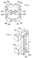
- FIG. 2 is a perspective view partly broken away and showing a first magnetic coupling included in the device of FIG. 1;
- FIG. 3 is a perspective view showing the arrangement of permanent magnets providing a drive portion of the first magnetic coupling of FIG. 2;
- FIG. 4 is a perspective view showing the arrangement of permanent magnets of a first permanent magnet device included in the first magnetic coupling of FIG. 2;
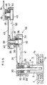
- FIG. 5 is a side elevation partly broken away and showing the main portion of a semiconductor wafer handling apparatus incorporating the magnetic drive device of FIG. 1;
- FIG. 6 is a plan view of the handling apparatus of FIG. 5;
- FIG. 7 is a view in vertical section showing another magnetic drive device embodying the invention;
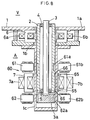
- FIG. 8 is a view in vertical section showing another magnetic drive device embodying the invention;
- FIG. 9 is a view in vertical section showing still another magnetic drive device embodying the invention; and
- FIG. 10 is a view in vertical section showing a magnetic coupling included in the device of FIG. 9.
- Several embodiments of the present invention will be described below with reference to the accompanying drawings. Throughout the drawings, like parts are designated by like reference numerals. In the following description, the upper and lower sides of FIGS. 1, 5 and 7 to 9 will be referred to as "upper" and "lower," respectively. The direction of rotation will be referred to as the device is seen from above. With respect to the direction of rotation, the clockwise direction will be referred to as "rightward," and the counterclowise direction as "leftward."
- FIG. 1 shows a magnetic drive device disposed in the atmosphere A outside a
vacuum shield 1 for driving anouter rotor 2 and aninner rotor 3 which are arranged in a vacuum V inside theshield 1. - The
shield 1 comprises an uppercylindrical wall 1b extending vertically downward from an apertured portion of ahorizontal wall 1a, and a lowercylindrical wall 1c having a bottom and extending vertically downward from the lower end of thewall 1b. The tworotors cylindrical walls - The
outer rotor 2 is in the form of a vertical hollow cylinder and is fitted in thecylindrical walls rotor 2 within the walls. - The
inner rotor 3 is in the form of a vertical rod and is inserted in theouter rotor 2 coaxially therewith so as to project at its upper and lower ends beyond theouter rotor 2. Theinner rotor 3 is supported by upper and lower twobearings outer rotor 2 so as to be rotatable relative to therotor 2 although vertically immovable relative thereto. The lower end of theinner rotor 3 projecting downward beyond the lower end of theouter rotor 2 has a large-diameter portion 3a in the form of a short column and approximately equal to theouter rotor 2 in outside diameter. - A fixed
magnetic bearing 6 is fixed to the uppercylindrical wall 1b around theouter rotor 2. - A
movable unit 8 is disposed around the lowercylindrical wall 1c. - The
movable unit 8 comprises a movable housing 9, movablemagnetic bearing 7 disposed in the middle portion of the housing 9, drive portion (first drive portion) 11 of a firstmagnetic coupling 10 disposed in the upper portion of the housing 9, and drive portion (second drive portion ) 13 of a secondmagnetic coupling 12 disposed in a lower portion of the housing 9. - The fixed
magnetic bearing 6 and the movablemagnetic bearing 7 are those already known and comprise, for example, fourelectromagnets outer rotor 2 chiefly radially thereof. FIG. 1 shows only twoelectromagnets - The housing 9 is moved vertically along the lower
cylindrical wall 1c by unillustrated suitable means. - The first and
second drive portions cylindrical wall 1c and are respectively supported bybearings second drive portions - The
drive portion 11 of the firstmagnetic coupling 10 is opposed to the outer peripheral surface of a lower portion of theouter rotor 2 with the lowercylindrical wall 1c positioned therebetween. The firstmagnetic coupling 10 has a driven portion provided in the lower portion peripheral surface of theouter rotor 2. - FIGS. 2 to 4 show the first
magnetic coupling 10 in greater detail. -
Permanent magnet devices first drive portion 11 and the lower portion of theouter rotor 2, respectively, at four portions equally divided circumferentially thereof. - The
permanent magnet device 18a (18b, 18c, 18d) comprises an upperpermanent magnet 19a (19b, 19c, 19d) and a lowerpermanent magnet 20a (20b, 20c, 20d) which are fixed as vertically spaced apart in the inner peripheral surface of thefirst drive portion 11 and extend circumferentially thereof, and a leftpermanent magnet 21a (21b, 21c, 21d) and a rightpermanent magnet 22a (22b, 22c, 22d) which extend vertically and are fixed in the outer peripheral surface of theouter rotor 2 and spaced apart circumferetially thereof. The upper andlower magnets 19a to 19d and 20a to 20d of thefirst drive portion 11 each have a magnetic pole at each of its right and left ends. The upper andlower magnets 19a (19b, 19c, 19d) and 20a (20b, 20c, 20d) are opposite in polarity at their right ends, as well as at their left ends. The left andright magnets 21a to 21d and 22a to 22d of theouter rotor 2 each have a magnetic pole at each of its upper and lower ends. The left andright magnets 21a (21b, 21c, 21d) and 22a (22b, 22c, 22d) are opposite in polarity at their upper ends, as well as at their lower ends. The upper-end magnetic pole of theleft magnet 21a (21b, 21c, 21d) is opposed to the left-end magnetic pole of theupper magnet 19a (19b, 19c, 19d), the lower-end pole of theleft magnet 21a (21b, 21c, 21d) to the left-end pole of thelower magnet 20a (20b, 20c, 20d), the upper-end pole of theright magnet 22a (22b, 22c, 22d) to the right-end pole of theupper magnet 19a (19b, 19c, 19d), and the lower-end pole of theright magnet 22a (22b, 22c, 22d) to the right-end pole of thelower magnet 20a (20b, 20c, 20d). The two magnetic poles in each opposed pair are opposite in polarity. The firstpermanent magnet device 18a and the thirdpermanent magnet device 18c positioned symmetrically therewith are the same in the arrangement of magnetic poles. The secondpermanent magnet device 18b and the fourthpermanent magnet device 18d positioned symmetrically therewith are identical in the arrangement of poles. Accordingly, themagnet devices 18a to 18d each have a closed magnetic path spreading out radially, axially and circumferentially of theouter rotor 2. - More specifically, in the first and
third magnet devices upper mangets lower magnets left magnets right magnets outer rotor 2 as indicated in a dot-and-dash line in FIG. 4. - Conversely in the second and fourth
magnetic devices upper mangets lower magnets left magnets right magnets outer rotor 2. - Since the closed magnetic paths are formed by the four
permanent magnet devices 18a to 18d, attraction acts between thefirst drive portion 11 and theouter rotor 2. Because these magnetic paths spread out radially, axially and circumferentially of theouter rotor 2, thefirst drive portion 11 transmits a torque and an axial holding force to theouter rotor 2. When thefirst drive portion 11 is rotated, theouter rotor 2 is also rotated. When axially moved, thefirst drive portion 11 moves theouter rotor 2 also axially thereof. - The
drive portion 13 of the secondmagnetic coupling 12 is opposed to the outer peripheral surface of large-diameter portion 3a of theinner rotor 3 with the lowercylindrical wall 1c positioned therebetween. The secondmagnetic coupling 12 has a driven portion provided in the peripheral surface of the large-diameter portion 3a. The secondmagnetic coupling 12 is known as disclosed for example, in Unexamined Japanese Patent Publication SHO 56-150650. The torque of thesecond drive portion 13 is transmitted to theinner rotor 3. - When the movable housing 9 moves upward or downward, the
drive portions couplings rotors first coupling 10. - When the first motor rotates the
drive portion 11 of the firstmagnetic coupling 10, the torque is transmitted to theouter rotor 2 to rotate theouter rotor 2 independently of theinner rotor 3. Similarly, when thedrive portion 13 of the secondmagnetic coupling 12 is rotated by the second motor, the torque is transmitted to theinner rotor 3, rotating theinner rotor 3 independently of theouter rotor 2. - FIGS. 5 and 6 show the main portion of an example of semiconductor wafer handling apparatus including the magnetic drive device described. In this case, the
outer rotor 2 projects upward beyond thehorizontal wall 1a of thevacuum shield 1 by a larger distance than in FIG. 1. Theinner rotor 3 greatly projects upward beyond the upper end of theouter rotor 2. - The
outer rotor 2 of the magnetic drive device projects upward beyond the upper end of thecylindrical wall 1b of thevacuum shield 1 into a vacuum V above thehorizontal wall 1a. Afirst drive pulley 29 in the form of a cylinder is fixed to the upper end of theouter rotor 2 with acylindrical housing 28 interposed therebetween. A horizontalfirst arm 31 has a base end fixed by aflange member 30 to the upper end of theinner rotor 3 which extends upward beyond thepulley 29. Theflange member 30 has a lower portion extending through thepulley 29 to an inside upper portion of thehousing 28.Bearings pulley 29 and thehousing 28, rendering theouter rotor 2 and thefirst arm 31 rotatable relative to each other. Thefirst arm 31 is in the form of a hollow member having an open bottom side. Thepulley 29 is covered with the base end of the arm. - The
first arm 31 has aboss portion 34 provided around an opening formed in the upper wall of its forward end. Asecond drive pulley 36 is fixed to the top of theboss portion 34 with acylindrical housing 35 interposed therebetween. A vertical secondarm rotating shaft 39 extends through and is rotatably supported by theboss portion 34 of thefirst arm 31 and thehousing 35, withbearings shaft 39 inside the boss portion and the housing. Theshaft 39 has a lower end fixedly carrying a first drivenpulley 40 which is positioned inside thefirst arm 31 and under theboss portion 34 and which is coupled to thefirst drive pulley 29 by afirst belt 41. Theshaft 39 extends upward beyond thesecond drive pulley 36. Asecond arm 43 has a base end fixed by aflange member 42 to the upper end of theshaft 39. Thesecond arm 43 is also in the form of a hollow member having an open bottom side. Thesecond drive pulley 36 is covered with the arm base end. - The
second arm 43 has aboss portion 44 provided around an opening in the upper wall of its forward end. Acylindrical housing 45 is fixed to the top of theboss portion 44. Aholder rotating shaft 48 extends through theboss portion 44 and thehousing 45 and is rotatably supported bybearings shaft 48 has a lower end fixedly carrying a second drivenpulley 49, which is positioned inside thesecond arm 43 and under theboss portion 44 and which is coupled to thesecond drive pulley 36 by asecond belt 50. Theshaft 48, extending upward beyond thehousing 45, has awafer holder 51 fixed to the upper end of the shaft. Thefirst arm 31, thesecond arm 43 and thewafer holder 51 constitute ascalar robot 52. - The diameter ratio of the
first drive pulley 29 to the first drivenpulley 40 is 2:1. The diameter ratio of thesecond drive pulley 36 to the second drivenpulley 49 is 1:2. The axis-to-axis distance between theinner rotor 3 band the secondarm rotating shaft 39 is equal to the axis-to-axis distance between the secondarm rotating shaft 39 and theholder rotating shaft 48. - When the two
rotors rotors holder 51 rotate together without changing the relative position relationship therebetween. - When the two
rotors arms scalar robot 52 to shift theholder 51 radially of therotors outer rotor 2 is at rest at this time, theholder 51 does not shift circumferentially of therotors rotors outer rotor 2 is in rotation, theholder 51 shifts also in the circumferential direction. In either case, the angle theholder 51 makes with a straight line through the axis of the tworotors holder rotating shaft 48 is constant at all times, permitting theholder 51 to move while always remaining in a definite posture with respect to the radial direction of therotors - FIGS. 7, 8 and 9 show other magnetic devices which are each disposed in the atmosphere A outside a
vacuum shield 1 for driving anouter rotor 2 and aninner rotor 3 which are arranged in a vacuum V inside theshield 1. - The magnetic drive device shown in FIG. 7 has a
movable unit 60 corresponding to themovable unit 8 of FIG. 1 and comprising a firstdirect drive motor 61 in place of the firstmagnetic coupling 10 of FIG. 1 and a seconddirect drive motor 62 in place of the secondmagnetic coupling 12 of FIG. 1. Thefirst motor 61 has a rotor (first motor rotor) 61a formed in an outer peripheral portion of theouter rotor 2. A motor stator (first motor stator) 61b for directly driving thefirst motor rotor 61a is disposed around a lowercylindrical wall 1c. Thesecond motor 62 has a motor rotor (second motor rotor) 62a formed in the outer periphery of a large-diameter portion 3a of theinner rotor 3. A motor stator (second motor stator) 62b for directly driving thesecond motor rotor 62a is disposed around the lowercylindrical wall 1c. Themovable unit 60 further comprises a movablemagnetic bearing 7 for holding theouter rotor 2 radially and axially thereof. The movablemagnetic bearing 7 and the first andsecond motor stators magnetic bearing 7 and the twomotor stators cylindrical wall 1c. - When the
movable unit 60 moves upward or downward in this case, the tworotors magnetic bearing 7. When thefirst motor rotor 61a is driven by thefirst motor stator 61b, theouter rotor 2 is rotated independently of theinner rotor 3. Similarly, when thesecond motor rotor 62a is driven by thesecond motor stator 62b, theinner rotor 3 is rotated independently of theouter rotor 2. - The present device is the same as the device shown in FIG. 1 with the exception of the above feature.
- In the case of the magnetic drive device shown in FIG. 8, each of
electromagnets magnetic bearing 7 and anouter rotor 2 are toothed at portions thereof opposed to each other as indicated at 65, 66, respectively. Thesetoothed portions toothed portion 65 of eachelectromagnet 7a (7b) is provided by forming a plurality of circumferential grooves in the inner periphery thereof, while thetoothed portion 66 of theouter rotor 2 is provided by forming a plurality of annular grooves in the outer periphery thereof. - With the exception of the above feature, the device has the same construction as the device of FIG. 7.
- In the case of the magnetic drive device shown in FIG. 9, a
movable unit 67 has a movable housing (not shown) which is provided with adrive portion 69 of amagnetic coupling 68 in addition to a movablemagnetic bearing 7 and first andsecond motor stators magnetic coupling 68 has a driven portion formed in the outer peripheral surface of anouter rotor 2 and opposed to thedrive portion 69. The magneticcoupling drive portion 69 is mounted on the movable housing so as to be freely rotatable and movable upward or downward with the movablemagnetic bearing 7 and themotor stators - The
magnetic coupling 68 is a known one, an example of which is shown in FIG. 10. With reference to FIG. 10, thedrive portion 69 of thecoupling 68 is in the form of a ring and comprises a plurality ofmagnetic pole members 70 arranged axially in its inner periphery at a spacing, and a plurality ofpermanent magnets 71 arranged between thepole members 70. In corresponding relation with the drive portion, theouter rotor 2 is provided in its outer periphery with a plurality ofmagnetic pole members 72 arranged axially at a spacing, and a plurality ofpermanent magnets 73 arranged between thepole members 72, whereby the drive portion of thecoupling 68 is formed. Asleeve 74 is fitted around thesepole members 72 andpermanent magnets 73. Each of thepermanent magnets permanent magnets 71 and themagnetic pole members 70 of thedrive portion 69 and thepermanent magnets 73 and themagnetic pole members 72 of the driven portion as indicated by arrows in FIG. 10. By virtue of a magnetic attraction occurring between the driveportion pole members 70 and the drivenportion pole members 72, an axial holding force is transmitted from thedrive portion 69 to theouter rotor 2, permitting thedrive portion 69 to rotate with the rotation of theouter rotor 2. - When the
movable unit 67 moves upward or downward in this case, the tworotors magnetic bearing 7 and the axial holding force given by themagnetic coupling 68. - With the exception of the feature described above, the present device is the same as the device shown in FIG. 7.
- The present invention can be embodied also as magnetic drive devices wherein only one rotor is driven in rotation and also axially thereof. For example, when the embodiment of FIG. 1 is so modified, only one
rotor 2 is disposed in thecylindrical walls drive portion 11 of the firstmagnetic coupling 10 for driving therotor 2 in rotation and in the axial direction. The same is true of the embodiments of FIGS. 7 to 9.
Claims (10)
- A magnetic drive device comprising a rotor disposed inside a cylindrical wall so as to be rotatable and axially movable, a fixed magnetic bearing fixedly provided on the cylindrical wall for holding the rotor radially thereof, a magnetic coupling having a drive portion disposed around the cylindrical wall so as to be rotatable and axially movable for transmitting a torque and an axial holding force to the rotor, and a movable magnetic bearing disposed around the cylindrical wall so as to be axially movable with the drive portion of the magnetic coupling for holding the rotor radially thereof.
- A magnetic drive device as defined in claim 1 wherein the drive portion of the magnetic coupling and a peripheral surface of the rotor opposed thereto with the cylindrical wall positioned therebetween are provided with a plurality of permanent magnet devices each comprising opposed permanent magnets, the permanent magnets of each permanent magnet device being so arranged as to form in the permanent magnet device a closed magnetic path spreading out radially and axially of the rotor.
- A magnetic drive device as defined in claim 2 wherein the permanent magnets of each permanent magnet device are so arranged as to form in the permanent magnet device a closed magnetic path spreading out radially, axially and circumferentially of the rotor.
- A magnetic drive device as defined in claim 1 wherein the rotor is an outer rotor in the form of a cylinder, and the magnetic coupling is a first magnetic coupling, an inner rotor being inserted in the outer rotor so as to project at least at an end portion thereof beyond an end of the outer rotor and supported rotatably relative to the outer rotor, a second magnetic coupling having a drive portion disposed around the cylindrical wall so as to be axially movable with the first magnetic coupling drive portion and the movable magnetic bearing and to be rotatable, the second magnetic coupling drive portion being operable to transmit a torque and an axial holding force to the portion of the inner rotor projecting beyond the end of the outer rotor.
- A magnetic drive device comprising a rotatable member disposed inside a cylindrical wall so as to be rotatable and axially movable, a fixed magnetic bearing fixedly provided on the cylindrical wall for holding the rotatable member radially thereof, a motor stator disposed around the cylindrical wall so as to be axially movable for directly driving a motor rotor formed on the rotatable member, and a movable magnetic bearing disposed around the cylindrical wall so as to be axially movable with the motor stator for holding the rotatable member radially and axially thereof.
- A magnetic drive device as defined in claim 5 wherein the rotatable member is an outer rotor in the form of a cylinder, the motor rotor being a first motor rotor, the motor stator being a first motor stator, an inner rotor being inserted in the outer rotor so as to project at least at an end portion thereof beyond an end of the outer rotor and supported rotatably relative to the outer rotor, the portion of the inner rotor projecting beyond the end of the outer rotor being formed with a second motor rotor, a second motor stator being disposed around the cylindrical wall so as to be axially movable with the first motor stator and the movable magnetic bearing for directly driving the second motor rotor.
- A magnetic drive device as defined in claim 5 wherein the movable magnetic bearing and the rotatable member are toothed at portions thereof opposed to each other for producing an axial holding force.
- A magnetic drive device as defined in claim 6 wherein the movable magnetic bearing and the outer rotor are toothed at portions thereof opposed to each other for producing an axial holding force.
- A magnetic drive device as defined in claim 5 wherein a magnetic coupling has a drive portion for transmitting an axial holding force to the rotatable member, and the drive portion is disposed around the cylindrical wall so as to be axially movable with the motor stator and the movable magnetic bearing.
- A magnetic drive device as defined in claim 6 wherein a magnetic coupling has a drive portion for transmitting an axial holding force to the outer rotor, and the drive portion is disposed around the cylindrical wall so as to be axially movable with the first motor stator, the second motor stator and the movable magnetic bearing.
Applications Claiming Priority (2)
| Application Number | Priority Date | Filing Date | Title |
|---|---|---|---|
| JP10281591 | 1991-05-08 | ||
| JP102815/91 | 1991-05-08 |
Publications (2)
| Publication Number | Publication Date |
|---|---|
| EP0512516A1 true EP0512516A1 (en) | 1992-11-11 |
| EP0512516B1 EP0512516B1 (en) | 1995-12-20 |
Family
ID=14337530
Family Applications (1)
| Application Number | Title | Priority Date | Filing Date |
|---|---|---|---|
| EP92107653A Expired - Lifetime EP0512516B1 (en) | 1991-05-08 | 1992-05-06 | Magnetic drive device |
Country Status (3)
| Country | Link |
|---|---|
| US (1) | US5270600A (en) |
| EP (1) | EP0512516B1 (en) |
| DE (1) | DE69206872T2 (en) |
Cited By (11)
| Publication number | Priority date | Publication date | Assignee | Title |
|---|---|---|---|---|
| WO1995013480A1 (en) * | 1993-11-09 | 1995-05-18 | Societe De Mecanique Magnetique | Device for mounting and driving a spindle, particularly a textile spindle |
| FR2715011A1 (en) * | 1994-01-13 | 1995-07-13 | Schlumberger Ind Sa | Rotational drive system of two mechanical members by magnetic coupling and fluid meter comprising such a system. |
| EP0696242A1 (en) † | 1993-04-16 | 1996-02-14 | Brooks Automation, Inc. | Articulated arm transfer device |
| DE19637270A1 (en) * | 1996-09-13 | 1998-03-19 | Schlafhorst & Co W | Pot spinning device |
| EP0899855A1 (en) * | 1997-08-25 | 1999-03-03 | Sulzer Electronics AG | Rotary device with magnetic bearing |
| EP0994266A2 (en) * | 1998-10-16 | 2000-04-19 | Rolls-Royce Plc | Rotating assembly and support therefor |
| DE202005020288U1 (en) * | 2005-12-23 | 2007-05-03 | H. Wernert & Co. Ohg | Permanent magnet contactless radial rotary coupler for e.g. vertical pump, has magnets polarized equally in circumferential direction, where magnets form non-contact operating passive radial support for receiving radial forces between units |
| EP1801420A2 (en) | 2005-12-23 | 2007-06-27 | H. Wernert & Co. oHG | Centrifugal pump with magnetic coupling |
| EP1845259A1 (en) * | 2006-04-12 | 2007-10-17 | Aisin Seiki Kabushiki Kaisha | Magnetic drive pump |
| WO2016083096A1 (en) * | 2014-11-26 | 2016-06-02 | Mahle International Gmbh | Device for transmitting rotational motions without contact |
| CN114673728A (en) * | 2020-12-24 | 2022-06-28 | 迈格钠磁动力股份有限公司 | Permanent magnet thrust suspension bearing and control method thereof |
Families Citing this family (51)
| Publication number | Priority date | Publication date | Assignee | Title |
|---|---|---|---|---|
| US5447409A (en) * | 1989-10-20 | 1995-09-05 | Applied Materials, Inc. | Robot assembly |
| DE69032945T2 (en) * | 1989-10-20 | 1999-09-16 | Applied Materials Inc | Robotic device |
| US5155336A (en) * | 1990-01-19 | 1992-10-13 | Applied Materials, Inc. | Rapid thermal heating apparatus and method |
| JPH0627768U (en) * | 1992-09-17 | 1994-04-12 | セイコー精機株式会社 | Carrier |
| US5431529A (en) * | 1992-12-28 | 1995-07-11 | Brooks Automation, Inc. | Articulated arm transfer device |
| US5376862A (en) * | 1993-01-28 | 1994-12-27 | Applied Materials, Inc. | Dual coaxial magnetic couplers for vacuum chamber robot assembly |
| DE4405701A1 (en) * | 1994-02-23 | 1995-08-24 | Philips Patentverwaltung | Magnetic gear with several magnetically interacting, relatively movable parts |
| WO1996019034A1 (en) * | 1994-12-12 | 1996-06-20 | Jorge De Armas | Electromagnetic-coupled/levitated apparatus and method for rotating equipment |
| TW331652B (en) * | 1995-06-16 | 1998-05-11 | Ebara Corp | Thin film vapor deposition apparatus |
| US5647724A (en) | 1995-10-27 | 1997-07-15 | Brooks Automation Inc. | Substrate transport apparatus with dual substrate holders |
| US6231297B1 (en) | 1995-10-27 | 2001-05-15 | Brooks Automation, Inc. | Substrate transport apparatus with angled arms |
| US6299404B1 (en) | 1995-10-27 | 2001-10-09 | Brooks Automation Inc. | Substrate transport apparatus with double substrate holders |
| US6481956B1 (en) | 1995-10-27 | 2002-11-19 | Brooks Automation Inc. | Method of transferring substrates with two different substrate holding end effectors |
| JP3740770B2 (en) * | 1995-12-28 | 2006-02-01 | 日本精工株式会社 | Sealed actuator |
| US20040005211A1 (en) * | 1996-02-28 | 2004-01-08 | Lowrance Robert B. | Multiple independent robot assembly and apparatus and control system for processing and transferring semiconductor wafers |
| US6102164A (en) * | 1996-02-28 | 2000-08-15 | Applied Materials, Inc. | Multiple independent robot assembly and apparatus for processing and transferring semiconductor wafers |
| US6062798A (en) | 1996-06-13 | 2000-05-16 | Brooks Automation, Inc. | Multi-level substrate processing apparatus |
| US5931626A (en) * | 1998-01-16 | 1999-08-03 | Brooks Automation Inc. | Robot mounting de-coupling technique |
| US6132165A (en) * | 1998-02-23 | 2000-10-17 | Applied Materials, Inc. | Single drive, dual plane robot |
| US6547510B1 (en) | 1998-05-04 | 2003-04-15 | Brooks Automation Inc. | Substrate transport apparatus with coaxial drive shafts and dual independent scara arms |
| US6949854B1 (en) * | 2001-03-16 | 2005-09-27 | Michael Schlicht | Method and apparatus for a continuously variable-ratio transmission |
| US6800833B2 (en) | 2002-03-29 | 2004-10-05 | Mariusch Gregor | Electromagnetically levitated substrate support |
| TW547869U (en) * | 2002-07-10 | 2003-08-11 | Hon Hai Prec Ind Co Ltd | Bearing device for motor |
| DE102004024883B4 (en) * | 2004-05-19 | 2006-02-02 | Siemens Ag | drive system |
| US7688017B2 (en) * | 2005-02-12 | 2010-03-30 | Applied Materials, Inc. | Multi-axis vacuum motor assembly |
| JP2006262637A (en) * | 2005-03-17 | 2006-09-28 | Toshiba Corp | Electrostatic actuator and imaging device using the same |
| US8573919B2 (en) * | 2005-07-11 | 2013-11-05 | Brooks Automation, Inc. | Substrate transport apparatus |
| US7571780B2 (en) | 2006-03-24 | 2009-08-11 | Hall David R | Jack element for a drill bit |
| US8522897B2 (en) | 2005-11-21 | 2013-09-03 | Schlumberger Technology Corporation | Lead the bit rotary steerable tool |
| US8267196B2 (en) | 2005-11-21 | 2012-09-18 | Schlumberger Technology Corporation | Flow guide actuation |
| US8297375B2 (en) | 2005-11-21 | 2012-10-30 | Schlumberger Technology Corporation | Downhole turbine |
| US8360174B2 (en) | 2006-03-23 | 2013-01-29 | Schlumberger Technology Corporation | Lead the bit rotary steerable tool |
| DE102006003117A1 (en) * | 2006-01-18 | 2007-07-19 | Institut für Bioprozess- und Analysenmesstechnik e.V. | Energy transferring device for use in e.g. mini environment box, has inner carriage and rotors converted into movement having more than degree of freedom or into two movements having just one degree of freedom |
| EP1826889B1 (en) * | 2006-02-24 | 2015-09-30 | ThyssenKrupp Aufzugswerke GmbH | Method and apparatus for mounting magnets |
| US9752615B2 (en) | 2007-06-27 | 2017-09-05 | Brooks Automation, Inc. | Reduced-complexity self-bearing brushless DC motor |
| US8823294B2 (en) | 2007-06-27 | 2014-09-02 | Brooks Automation, Inc. | Commutation of an electromagnetic propulsion and guidance system |
| JP5663304B2 (en) | 2007-06-27 | 2015-02-04 | ブルックス オートメーション インコーポレイテッド | Multi-dimensional position sensor |
| US8659205B2 (en) * | 2007-06-27 | 2014-02-25 | Brooks Automation, Inc. | Motor stator with lift capability and reduced cogging characteristics |
| CN101790673B (en) | 2007-06-27 | 2013-08-28 | 布鲁克斯自动化公司 | Position feedback for self bearing motor |
| US8283813B2 (en) * | 2007-06-27 | 2012-10-09 | Brooks Automation, Inc. | Robot drive with magnetic spindle bearings |
| JP2011514652A (en) | 2007-07-17 | 2011-05-06 | ブルックス オートメーション インコーポレイテッド | Substrate processing apparatus with motor integrated in chamber wall |
| US7434634B1 (en) | 2007-11-14 | 2008-10-14 | Hall David R | Downhole turbine |
| KR101829397B1 (en) | 2011-09-16 | 2018-02-19 | 퍼시몬 테크놀로지스 코포레이션 | Low variability robot |
| CN110620473A (en) | 2011-09-16 | 2019-12-27 | 柿子技术公司 | Robot drive with passive rotor |
| US10269604B2 (en) | 2014-01-21 | 2019-04-23 | Persimmon Technologies Corporation | Substrate transport vacuum platform |
| TWI765936B (en) | 2016-11-29 | 2022-06-01 | 美商東京威力科創Fsi股份有限公司 | Translating and rotating chuck for processing microelectronic substrates in a process chamber |
| CN110268513A (en) | 2017-01-27 | 2019-09-20 | 东京毅力科创Fsi公司 | System and method for the rotation and translation substrate in process chamber |
| DE102017124981B4 (en) | 2017-10-25 | 2024-03-07 | Schölly Fiberoptic GmbH | Magnetic clutch |
| US11545387B2 (en) * | 2018-07-13 | 2023-01-03 | Tel Manufacturing And Engineering Of America, Inc. | Magnetic integrated lift pin system for a chemical processing chamber |
| CN109501983B (en) * | 2018-11-20 | 2023-06-23 | 西安工业大学 | Underwater actuator and method thereof |
| JP2021158751A (en) * | 2020-03-26 | 2021-10-07 | セイコーエプソン株式会社 | Robot and robot system |
Citations (4)
| Publication number | Priority date | Publication date | Assignee | Title |
|---|---|---|---|---|
| CH469209A (en) * | 1967-07-31 | 1969-02-28 | Const Mecanique | Magnetic coupling for the transmission of a reciprocating longitudinal movement |
| EP0037368A1 (en) * | 1980-03-28 | 1981-10-07 | Siemens Aktiengesellschaft | Radial gap magnetic rotary coupling |
| EP0034992B1 (en) * | 1980-02-26 | 1983-05-11 | ANVAR Agence Nationale de Valorisation de la Recherche | Permanent-magnet couplers |
| US4998859A (en) * | 1987-10-16 | 1991-03-12 | Seiko Seiki Kabushik Kaisha | Transferring apparatus operated in a vacuum chamber |
Family Cites Families (3)
| Publication number | Priority date | Publication date | Assignee | Title |
|---|---|---|---|---|
| FR469209A (en) * | 1914-03-03 | 1914-07-27 | Marguerite Schaeffer | Spinning top with its gyratory launching device |
| DE3604270C1 (en) * | 1986-02-12 | 1987-07-02 | Christensen Inc Norton | Drilling tool for deep drilling |
| JPH03154791A (en) * | 1989-11-14 | 1991-07-02 | Sumitomo Eaton Noba Kk | Articulated arm for robot |
-
1992
- 1992-05-06 DE DE69206872T patent/DE69206872T2/en not_active Expired - Fee Related
- 1992-05-06 EP EP92107653A patent/EP0512516B1/en not_active Expired - Lifetime
- 1992-05-07 US US07/879,428 patent/US5270600A/en not_active Expired - Fee Related
Patent Citations (4)
| Publication number | Priority date | Publication date | Assignee | Title |
|---|---|---|---|---|
| CH469209A (en) * | 1967-07-31 | 1969-02-28 | Const Mecanique | Magnetic coupling for the transmission of a reciprocating longitudinal movement |
| EP0034992B1 (en) * | 1980-02-26 | 1983-05-11 | ANVAR Agence Nationale de Valorisation de la Recherche | Permanent-magnet couplers |
| EP0037368A1 (en) * | 1980-03-28 | 1981-10-07 | Siemens Aktiengesellschaft | Radial gap magnetic rotary coupling |
| US4998859A (en) * | 1987-10-16 | 1991-03-12 | Seiko Seiki Kabushik Kaisha | Transferring apparatus operated in a vacuum chamber |
Non-Patent Citations (2)
| Title |
|---|
| PATENT ABSTRACTS OF JAPAN vol. 11, no. 11 (E-470)(2458) 13 January 1987 & JP-A-61 185 039 ( HITACHI ) 18 August 1986 * |
| PATENT ABSTRACTS OF JAPAN vol. 11, no. 288 (E-542)(2735) 17 September 1987 & JP-A-62 089 471 ( HITACHI ) 23 April 1987 * |
Cited By (22)
| Publication number | Priority date | Publication date | Assignee | Title |
|---|---|---|---|---|
| EP0696242B2 (en) † | 1993-04-16 | 2004-10-13 | Brooks Automation, Inc. | Articulated arm transfer device |
| EP0696242A1 (en) † | 1993-04-16 | 1996-02-14 | Brooks Automation, Inc. | Articulated arm transfer device |
| CN1046654C (en) * | 1993-04-16 | 1999-11-24 | 布鲁克斯自动化公司 | Articulated arm transfer device |
| FR2712358A1 (en) * | 1993-11-09 | 1995-05-19 | Mecanique Magnetique Sa | Device for mounting and driving a spindle, in particular a textile spindle. |
| US5973430A (en) * | 1993-11-09 | 1999-10-26 | Societe De Mecanique Magnetique | Device for mounting and driving a spindle, particularly a textile spindle |
| WO1995013480A1 (en) * | 1993-11-09 | 1995-05-18 | Societe De Mecanique Magnetique | Device for mounting and driving a spindle, particularly a textile spindle |
| FR2715011A1 (en) * | 1994-01-13 | 1995-07-13 | Schlumberger Ind Sa | Rotational drive system of two mechanical members by magnetic coupling and fluid meter comprising such a system. |
| EP0663717A1 (en) * | 1994-01-13 | 1995-07-19 | Schlumberger Industries S.A. | Magnetic coupling system for driving two rotating elements and fluid meter comprising such a system |
| DE19637270A1 (en) * | 1996-09-13 | 1998-03-19 | Schlafhorst & Co W | Pot spinning device |
| US6223512B1 (en) | 1996-09-13 | 2001-05-01 | W. Schlafhorst Ag & Co. | Pot spinning device |
| EP0899855A1 (en) * | 1997-08-25 | 1999-03-03 | Sulzer Electronics AG | Rotary device with magnetic bearing |
| US7112903B1 (en) | 1997-08-25 | 2006-09-26 | Levitronix Llc | Magnetically journalled rotational arrangement including a rotor for generating a unipolar bias magnetic flux |
| EP0994266A3 (en) * | 1998-10-16 | 2001-04-04 | Rolls-Royce Plc | Rotating assembly and support therefor |
| EP0994266A2 (en) * | 1998-10-16 | 2000-04-19 | Rolls-Royce Plc | Rotating assembly and support therefor |
| DE202005020288U1 (en) * | 2005-12-23 | 2007-05-03 | H. Wernert & Co. Ohg | Permanent magnet contactless radial rotary coupler for e.g. vertical pump, has magnets polarized equally in circumferential direction, where magnets form non-contact operating passive radial support for receiving radial forces between units |
| EP1801420A2 (en) | 2005-12-23 | 2007-06-27 | H. Wernert & Co. oHG | Centrifugal pump with magnetic coupling |
| EP1845259A1 (en) * | 2006-04-12 | 2007-10-17 | Aisin Seiki Kabushiki Kaisha | Magnetic drive pump |
| US7922464B2 (en) | 2006-04-12 | 2011-04-12 | Aisin Seiki Kabushiki Kaisha | Magnetic drive pump |
| WO2016083096A1 (en) * | 2014-11-26 | 2016-06-02 | Mahle International Gmbh | Device for transmitting rotational motions without contact |
| US10361617B2 (en) | 2014-11-26 | 2019-07-23 | Mahle International Gmbh | Magnetic coupling device for transmitting rotational motions without contact |
| CN114673728A (en) * | 2020-12-24 | 2022-06-28 | 迈格钠磁动力股份有限公司 | Permanent magnet thrust suspension bearing and control method thereof |
| CN114673728B (en) * | 2020-12-24 | 2024-01-26 | 迈格钠磁动力股份有限公司 | Permanent magnet thrust suspension bearing and control method thereof |
Also Published As
| Publication number | Publication date |
|---|---|
| EP0512516B1 (en) | 1995-12-20 |
| US5270600A (en) | 1993-12-14 |
| DE69206872D1 (en) | 1996-02-01 |
| DE69206872T2 (en) | 1996-07-25 |
Similar Documents
| Publication | Publication Date | Title |
|---|---|---|
| US5270600A (en) | Magnetic drive device | |
| US5209699A (en) | Magnetic drive device | |
| EP0208124A2 (en) | Improvement in stepper motors | |
| EP0858867A2 (en) | Robot apparatus | |
| EP0130541B1 (en) | Flywheel apparatus | |
| US10612638B2 (en) | Speed reducer with electric motor | |
| JP2015142454A (en) | Actuator and multi-joint robot arm | |
| EP0335287A2 (en) | Permanent magnet motor with hysteresis drag cup coupling | |
| US5676025A (en) | Apparatus for balancing a rotary member | |
| JP2017184430A (en) | Rotary actuator and robot | |
| JPH07217653A (en) | Magnetic bearing | |
| JP7440675B2 (en) | Motor and motor manufacturing method | |
| JP3013264B2 (en) | Magnetic levitation actuator | |
| JP7050534B2 (en) | Pump device | |
| JPH05153753A (en) | Magnetic levitation actuator | |
| JPS6350947B2 (en) | ||
| JP3106369B2 (en) | Magnetic levitation actuator | |
| JP3930834B2 (en) | Axial type magnetic levitation rotating equipment and centrifugal pump | |
| JPH0192086A (en) | Joint section for robot | |
| GB2156013A (en) | Electromagnetic clutch | |
| CN218953949U (en) | Screw rod assembly and robot | |
| KR20230140660A (en) | Electric Motor | |
| JPS62160052A (en) | Fine adjustment and quick feeding motor | |
| KR830001951Y1 (en) | Electric Joint Mounting Motor | |
| JPH03155351A (en) | Shaft unit for magnetic pole position detector of vehicle motor |
Legal Events
| Date | Code | Title | Description |
|---|---|---|---|
| PUAI | Public reference made under article 153(3) epc to a published international application that has entered the european phase |
Free format text: ORIGINAL CODE: 0009012 |
|
| AK | Designated contracting states |
Kind code of ref document: A1 Designated state(s): DE FR GB |
|
| 17P | Request for examination filed |
Effective date: 19930112 |
|
| 17Q | First examination report despatched |
Effective date: 19940622 |
|
| GRAA | (expected) grant |
Free format text: ORIGINAL CODE: 0009210 |
|
| AK | Designated contracting states |
Kind code of ref document: B1 Designated state(s): DE FR GB |
|
| REF | Corresponds to: |
Ref document number: 69206872 Country of ref document: DE Date of ref document: 19960201 |
|
| ET | Fr: translation filed | ||
| PLBE | No opposition filed within time limit |
Free format text: ORIGINAL CODE: 0009261 |
|
| STAA | Information on the status of an ep patent application or granted ep patent |
Free format text: STATUS: NO OPPOSITION FILED WITHIN TIME LIMIT |
|
| 26N | No opposition filed | ||
| PGFP | Annual fee paid to national office [announced via postgrant information from national office to epo] |
Ref country code: GB Payment date: 19980427 Year of fee payment: 7 |
|
| PGFP | Annual fee paid to national office [announced via postgrant information from national office to epo] |
Ref country code: FR Payment date: 19980511 Year of fee payment: 7 |
|
| PGFP | Annual fee paid to national office [announced via postgrant information from national office to epo] |
Ref country code: DE Payment date: 19980515 Year of fee payment: 7 |
|
| PG25 | Lapsed in a contracting state [announced via postgrant information from national office to epo] |
Ref country code: GB Free format text: LAPSE BECAUSE OF NON-PAYMENT OF DUE FEES Effective date: 19990506 |
|
| GBPC | Gb: european patent ceased through non-payment of renewal fee |
Effective date: 19990506 |
|
| PG25 | Lapsed in a contracting state [announced via postgrant information from national office to epo] |
Ref country code: FR Free format text: LAPSE BECAUSE OF NON-PAYMENT OF DUE FEES Effective date: 20000131 |
|
| PG25 | Lapsed in a contracting state [announced via postgrant information from national office to epo] |
Ref country code: DE Free format text: LAPSE BECAUSE OF NON-PAYMENT OF DUE FEES Effective date: 20000301 |
|
| REG | Reference to a national code |
Ref country code: FR Ref legal event code: ST |