EP1801420A2 - Pompe centrifuge à accouplement magnétique - Google Patents
Pompe centrifuge à accouplement magnétique Download PDFInfo
- Publication number
- EP1801420A2 EP1801420A2 EP06026728A EP06026728A EP1801420A2 EP 1801420 A2 EP1801420 A2 EP 1801420A2 EP 06026728 A EP06026728 A EP 06026728A EP 06026728 A EP06026728 A EP 06026728A EP 1801420 A2 EP1801420 A2 EP 1801420A2
- Authority
- EP
- European Patent Office
- Prior art keywords
- magnets
- radially
- axial
- magnetic
- centrifugal pump
- Prior art date
- Legal status (The legal status is an assumption and is not a legal conclusion. Google has not performed a legal analysis and makes no representation as to the accuracy of the status listed.)
- Withdrawn
Links
- 230000005291 magnetic effect Effects 0.000 title claims description 50
- 238000010168 coupling process Methods 0.000 title claims description 28
- 238000005859 coupling reaction Methods 0.000 title claims description 28
- 230000008878 coupling Effects 0.000 title claims description 27
- 210000000056 organ Anatomy 0.000 claims description 33
- 230000001681 protective effect Effects 0.000 claims description 11
- 230000009471 action Effects 0.000 claims description 7
- 238000005192 partition Methods 0.000 claims description 7
- 230000008859 change Effects 0.000 claims description 5
- 239000000463 material Substances 0.000 claims description 5
- 150000001875 compounds Chemical class 0.000 claims description 3
- 238000000465 moulding Methods 0.000 claims description 3
- 239000007788 liquid Substances 0.000 description 14
- 238000010276 construction Methods 0.000 description 7
- 230000008901 benefit Effects 0.000 description 5
- 239000007789 gas Substances 0.000 description 5
- 238000001816 cooling Methods 0.000 description 4
- 230000005540 biological transmission Effects 0.000 description 3
- 238000005461 lubrication Methods 0.000 description 3
- 238000004519 manufacturing process Methods 0.000 description 3
- 230000001419 dependent effect Effects 0.000 description 2
- 230000002349 favourable effect Effects 0.000 description 2
- 239000000696 magnetic material Substances 0.000 description 2
- BGPVFRJUHWVFKM-UHFFFAOYSA-N N1=C2C=CC=CC2=[N+]([O-])C1(CC1)CCC21N=C1C=CC=CC1=[N+]2[O-] Chemical compound N1=C2C=CC=CC2=[N+]([O-])C1(CC1)CCC21N=C1C=CC=CC1=[N+]2[O-] BGPVFRJUHWVFKM-UHFFFAOYSA-N 0.000 description 1
- 206010041235 Snoring Diseases 0.000 description 1
- 230000002411 adverse Effects 0.000 description 1
- 230000007797 corrosion Effects 0.000 description 1
- 238000005260 corrosion Methods 0.000 description 1
- 230000006378 damage Effects 0.000 description 1
- 230000003247 decreasing effect Effects 0.000 description 1
- 230000002950 deficient Effects 0.000 description 1
- 208000001848 dysentery Diseases 0.000 description 1
- 230000000694 effects Effects 0.000 description 1
- 238000005516 engineering process Methods 0.000 description 1
- 230000005294 ferromagnetic effect Effects 0.000 description 1
- 238000011010 flushing procedure Methods 0.000 description 1
- 239000000383 hazardous chemical Substances 0.000 description 1
- 238000009434 installation Methods 0.000 description 1
- 230000003993 interaction Effects 0.000 description 1
- 230000001050 lubricating effect Effects 0.000 description 1
- 230000007257 malfunction Effects 0.000 description 1
- 238000012544 monitoring process Methods 0.000 description 1
- 238000005086 pumping Methods 0.000 description 1
- 230000003014 reinforcing effect Effects 0.000 description 1
- 239000000126 substance Substances 0.000 description 1
- 231100000331 toxic Toxicity 0.000 description 1
- 230000002588 toxic effect Effects 0.000 description 1
- 210000001835 viscera Anatomy 0.000 description 1
Images


Classifications
-
- F—MECHANICAL ENGINEERING; LIGHTING; HEATING; WEAPONS; BLASTING
- F04—POSITIVE - DISPLACEMENT MACHINES FOR LIQUIDS; PUMPS FOR LIQUIDS OR ELASTIC FLUIDS
- F04D—NON-POSITIVE-DISPLACEMENT PUMPS
- F04D29/00—Details, component parts, or accessories
- F04D29/04—Shafts or bearings, or assemblies thereof
-
- F—MECHANICAL ENGINEERING; LIGHTING; HEATING; WEAPONS; BLASTING
- F04—POSITIVE - DISPLACEMENT MACHINES FOR LIQUIDS; PUMPS FOR LIQUIDS OR ELASTIC FLUIDS
- F04D—NON-POSITIVE-DISPLACEMENT PUMPS
- F04D13/00—Pumping installations or systems
- F04D13/02—Units comprising pumps and their driving means
- F04D13/021—Units comprising pumps and their driving means containing a coupling
- F04D13/024—Units comprising pumps and their driving means containing a coupling a magnetic coupling
- F04D13/025—Details of the can separating the pump and drive area
-
- F—MECHANICAL ENGINEERING; LIGHTING; HEATING; WEAPONS; BLASTING
- F04—POSITIVE - DISPLACEMENT MACHINES FOR LIQUIDS; PUMPS FOR LIQUIDS OR ELASTIC FLUIDS
- F04D—NON-POSITIVE-DISPLACEMENT PUMPS
- F04D13/00—Pumping installations or systems
- F04D13/02—Units comprising pumps and their driving means
- F04D13/021—Units comprising pumps and their driving means containing a coupling
- F04D13/024—Units comprising pumps and their driving means containing a coupling a magnetic coupling
- F04D13/026—Details of the bearings
-
- F—MECHANICAL ENGINEERING; LIGHTING; HEATING; WEAPONS; BLASTING
- F04—POSITIVE - DISPLACEMENT MACHINES FOR LIQUIDS; PUMPS FOR LIQUIDS OR ELASTIC FLUIDS
- F04D—NON-POSITIVE-DISPLACEMENT PUMPS
- F04D13/00—Pumping installations or systems
- F04D13/02—Units comprising pumps and their driving means
- F04D13/021—Units comprising pumps and their driving means containing a coupling
- F04D13/024—Units comprising pumps and their driving means containing a coupling a magnetic coupling
- F04D13/027—Details of the magnetic circuit
-
- F—MECHANICAL ENGINEERING; LIGHTING; HEATING; WEAPONS; BLASTING
- F04—POSITIVE - DISPLACEMENT MACHINES FOR LIQUIDS; PUMPS FOR LIQUIDS OR ELASTIC FLUIDS
- F04D—NON-POSITIVE-DISPLACEMENT PUMPS
- F04D29/00—Details, component parts, or accessories
- F04D29/04—Shafts or bearings, or assemblies thereof
- F04D29/046—Bearings
- F04D29/047—Bearings hydrostatic; hydrodynamic
-
- F—MECHANICAL ENGINEERING; LIGHTING; HEATING; WEAPONS; BLASTING
- F04—POSITIVE - DISPLACEMENT MACHINES FOR LIQUIDS; PUMPS FOR LIQUIDS OR ELASTIC FLUIDS
- F04D—NON-POSITIVE-DISPLACEMENT PUMPS
- F04D29/00—Details, component parts, or accessories
- F04D29/04—Shafts or bearings, or assemblies thereof
- F04D29/046—Bearings
- F04D29/048—Bearings magnetic; electromagnetic
-
- H—ELECTRICITY
- H02—GENERATION; CONVERSION OR DISTRIBUTION OF ELECTRIC POWER
- H02K—DYNAMO-ELECTRIC MACHINES
- H02K49/00—Dynamo-electric clutches; Dynamo-electric brakes
- H02K49/10—Dynamo-electric clutches; Dynamo-electric brakes of the permanent-magnet type
- H02K49/104—Magnetic couplings consisting of only two coaxial rotary elements, i.e. the driving element and the driven element
- H02K49/106—Magnetic couplings consisting of only two coaxial rotary elements, i.e. the driving element and the driven element with a radial air gap
Definitions
- the invention relates to a centrifugal pump with a permanent magnetic non-contacting radial rotary coupling according to the preamble of claim 1.
- centrifugal pumps with magnetic coupling represent an important type of industrially used machines for the conveyance of liquids. Compared to the simpler centrifugal pumps with mechanical seal they have the advantage of a hermetic seal of the pump chamber. This makes them especially favorable for the promotion of aggressive or toxic liquids.
- the component referred to below as the pump housing (1) must in practice be made up of several parts. Some of them are wetted by the liquid to be pumped and must be sealed accordingly, others not.
- the pump housing (1) is here shown in one piece.
- FIG. 1 A first known pump of conventional design is shown in Figure 1 and is e.g. advertised in the brochure [1].
- a rotating pump impeller (4') is arranged, which receives the liquid to be conveyed via the suction nozzle (2 ') and ejects via the discharge nozzle (3') again under pressure.
- the radial bearing of the pump impeller (4 ') takes place by means of an impeller shaft (5') usually in plain bearings (9 ', 10'), the fixed parts in a bearing insert (11 ') are added.
- the lubrication and cooling of the plain bearings (9 ', 10') takes place by the liquid to be conveyed itself.
- the part of the rotary coupling which receives the driving torque through a partition wall, which is usually designed as a thin-walled split pot (12 '), and on the impeller shaft (5') to the pump impeller (4 ') passes, is used as a magnetic rotor ( 6 ').
- This is equipped with permanent magnets (7 '), which in turn must be surrounded before the corrosive and possibly also abrasive attack of the pumped liquid with a cylindrical protective jacket (8') liquid-tight. It should be mentioned only marginally that it may be necessary to protect an approximately metallic, that is to say ferromagnetic, magnet rotor (6 ') from corrosion as well as the shaft (5').
- the part of the rotary coupling which receives and transmits the driving torque of the motor via the drive shaft (15 ') is commonly referred to as a magnet driver (13'). He is also equipped accordingly with permanent magnets (14 '), but rotate in air and therefore are not subject to any special attack.
- the radial and axial bearing of the magnetic driver is carried out in commercial Wälzlagem (16 ').
- FIG. 2 Another common embodiment, especially for smaller pumps, is shown in Figure 2. Such a pump is e.g. advertised in [2].
- a bearing insert (11 ') can be inexpensively eliminated.
- the pump impeller (4 ') is combined with the magnet rotor (6'), the permanent magnet (7 ') and the protective jacket (8') to a part.
- This rotating impeller magnetic rotor unit (19 ') is slidably mounted here on a fixed axis (17').
- the axis (17 ') itself is fastened on one side via flow ribs (18') in the suction nozzle (2 '), supported on the other side in the specially shaped containment shell (12').
- design A The design described in FIGS. 1 and 2 and largely conventional today (referred to here as design A) is characterized in that the magnet driver (13 ') is arranged radially outwardly beyond the magnet rotor (6') lying further inward.
- This construction has the advantage that the high moment of inertia of the outside magnet driver (13 ') counteracts the too rapid startup of the driving motor and thus the tearing off of the magnetic coupling can be prevented more favorably.
- this design facilitates in particular a generously axially spaced radial bearing of the pump impeller (4 '), which is always desirable due to the high hydraulic forces within the pump.
- magnetic coupling pumps with a magnet rotor (6 ') located radially on the outside, which is in contact with the liquid, and an internal magnetic driver (13') are less frequently used.
- This embodiment is referred to as type B.
- Such pumps of type B for example, in the DE 01453760 .
- EP 0171514 or EP 0171515 described and are shown in Figure 3 must be carefully designed so that the magnetic coupling does not break off during rapid startup, which threatens here due to the outside magnetic rotor (6 ').
- the radially inner magnet driver (13 ') obstructs an axially pulled-out inner sliding bearing of the impeller magnetic rotor unit (19'), if not the containment shell (12 '), with its actual opening in the type B drive side must be facing the pump, adversely wound right is executed.
- An executed pump of type B is advertised in [3] and served as a model for the figure 3.
- magnetic radial rotary joints For transmitting torques through closed walls, e.g. from Lehmann, "Characteristics and Design of Magnetic Drives", in: “Leakage-free Pumps and Compressors", publisher G. Vetter, Vulkan-Verlag Essen, 2nd edition, 1992, magnetic radial rotary joints known.
- a driving member for example a shaft, which carries magnets with alternately radially inwardly and radially outwardly directed north pole along its circumference.
- the shaft is surrounded by an abortive member, for example a hollow cylinder, which carries on its inner circumference the same number of magnets also radially alternately magnetized.
- the driving and the abortive organ can also be interchanged in their function.
- the magnets of the shaft and the hollow cylinder are coupled in pairs by attractive magnetic forces, so that upon rotation of the driving member via the magnetic coupling, the driven member is rotated.
- several smaller magnets with the same radial magnetic orientation can be arranged adjacent to one another in the axial direction.
- Non-contact permanent magnetic bearing known.
- radially magnetized magnets interact with axially magnetized magnets (EP 0 034 992 A1 ), whereby the transmittable torque is reduced, or there act axially magnetized magnet magnetized in the circumferential direction together.
- the structure described there with annular magnets is expensive.
- the invention is therefore based on the object to improve the storage of the pump impeller in a generic centrifugal pump. Another object is to provide in a generic centrifugal pump with the greatest possible magnetic coupling between the pump impeller and the driving member a wear-free or low-locking and easy and inexpensive to produce axial storage without additional components.
- a centrifugal pump is provided, are arranged in the magnets of a driving member and the pump impeller, which are arranged coaxially with axial overlap, each checkerboard with in the circumferential and axial direction alternately radially inwardly and radially outwardly directed north pole ,
- the transmission of the torque is effected by pairwise magnetic attraction, while the function of an axial bearing of the pump impeller is generated by pole change in the axial direction. It is thus created a passive magnetic and thus wear-free axial bearing of the pump impeller, which can do without components that serve only the axial storage.
- the magnets contribute to both torque transmission and axial bearing.
- the driving member of the centrifugal pump is mounted in other ways, in particular mechanically, axially, in order to pass on the axial forces there.
- the magnets carried by the organs are axially spaced apart. As a result, fastening webs can be used for easy installation.
- a partition between the organs is provided.
- two space portions of a pump or the like can be permanently and easily separated from each other hermetically without wear-affected shaft seal or the like. An escape of hazardous substances into the environment is thus reliably prevented.
- At least one organ of magnetizable material is formed, whereby the magnetic effect of the magnets can be amplified.
- a protective and / or holding device in particular in the form of a sleeve covering the respective magnets, is provided on an organ.
- a protective and / or holding device in particular in the form of a sleeve covering the respective magnets, is provided on an organ.
- the protective and / or holding device can be formed from cast or pressed molding compound, in particular from plastic. Such a protective and / or holding device is simple and inexpensive to produce by conventional means.
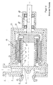
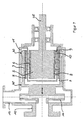
- a pump housing 11 has a coaxially arranged suction nozzle 12 and a radially arranged discharge nozzle 13. Between the suction nozzle 12 and the discharge nozzle 13 to a suction nozzle 12 coaxially arranged pump impeller 14 is provided which is (radially) within the pump only radially mounted, either near the axis by means of a bearing insert 41 held in the pump housing 11 small-caliber sliding bearing 39 ( Figures 5 and 6) or by means of a cup-shaped large-caliber sliding bearing 40 on the inside of the pump housing 11 ( Figures 7 and 8).
- the pump impeller 14 is rotatably driven by a drive shaft 35, which is mounted on the pump housing 11 in particular, wherein a permanent magnet non-contacting radial rotary coupling transmits the rotary drive force to the pump impeller and a partition wall 10 provided on the coupling gap 9 in the form of a known so-called split pot the drive side of the output side separates media.
- the drive shaft 35 is rotatably connected as shown in FIG. 5 and 6 with a cup-shaped drive rotor (outer member 3), while the pump impeller 14 is rotatably connected to an approximately cup-shaped output rotor (inner member 2).
- the pump impeller 14 thus forms together with a magnet (5, 6) carrying magnet rotor, here the output rotor, a structural unit (impeller magnetic rotor unit 19), which may be composed both in one piece and in many parts.
- At the inner circumference. 7 3 of the permanent magnet 5 are arranged distributed over the circumference, wherein the Polauscardi is radial and the polarities of axially adjacent and circumferentially adjacent magnets alternately - as shown in Figure 11 in principle.
- the outer magnets 5 are opposed to inner magnets 6 on the outer circumference 8 of the inner member 2, where they are suitably fixed with radial polarity alignment in the same number and arrangement as on the outer member 3.
- the polarities of axially adjacent magnets and the polarities of magnets adjacent to one another on the circumference are unlike those shown in principle in FIG. 11.
- the magnetic lines of action bridging the gap 9 are indicated as bold radial lines (FIGS. 5 to 8).
- the magnet pairings of the inner and outer members are axially opposite one another exactly when the pump impeller 14 is in its axial desired position. Since the pump impeller is only radially, namely by the inner plain bearing 39, but not axially supported, lead pressure or Saugst dealte the pump impeller to its axial deflection.
- Figure 6 is a deflection in the direction shown on the suction nozzle.
- FIGS. 9 to 16 The various possibilities of constructing the magnetic axial bearing for the pump impeller are explained in more detail with reference to the following FIGS. 9 to 16:
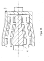
- the rotary radial coupling for a centrifugal pump or the like shown in FIGS. 9 and 10 comprises a driving (or optionally driven) member 2, in this case a hollow shaft which can be coupled to a motor or the like, and a driven (or optionally driving ) Organ 3, here a hollow cylinder with a front end connection for an impeller of a centrifugal pump or the like.
- the coaxially arranged members 2, 3 overlap each other axially. In the region of the axial overlap 4, each member 2, 3 carries, for example, four axially adjacent sets of radially opposite magnets 5a, 5b, 5c, 5d and 6a, 6b, 6c, 6d.
- the magnets 5 are along the inner Circumference 7 of the organ 3 is arranged, while the magnets 6 along the outer periphery 8 of the organ 2 are arranged.
- the magnets 5, 6 alternately radially inwardly and radially outwardly directed north poles, which are shown cross-hatched in the figures.
- the organs 2, 3 carry the same number, in particular equidistant magnets 5, 6, so that they are coupled in pairs by magnetic attraction and torque from the driving member 2 on the driven member 3 is transferable without slip.
- the arrangement of the magnets 6 is illustrated in FIG. 11.
- the illustrated radial magnetic radial coupling also has a noncontact passive, i. unregulated magnetic axial bearing.
- An axial restoring force counteracts due to the pole change in the axial direction of a relative axial deflection of the organs 2, 3.
- the field line profile when deflected in the axial direction is illustrated in FIG. 12.
- the axial restoring force is greater, the stronger the relative axial deflection.
- the organ 2 is thereby axially stored relative to the organ 3, in a stable equilibrium. Axial forces can be absorbed in this way.
- the arrangement shown thus represents a contactless axial bearing.
- the bearing stiffness of the axial bearing and the transferable torque between the organs 2, 3 are in the interaction as follows.
- the axial restoring force and thus the bearing stiffness increases with the number of pole changes in the axial direction per unit length.
- leakage losses also increase, so that the torque that can be transmitted between the organs 2, 3 becomes smaller.
- the transmittable torque thus increases with decreasing number of pole changes in the axial direction and also with increasing length of the magnets 5, 6 in the axial direction.
- the optimum number of axial pole changes per unit length and the optimal length of the magnets 5, 6 in the axial direction is therefore dependent on the respective requirements to determine the torque to be transmitted and the bearing stiffness, for example, empirically.
- a range between 50% and 90% of the transferable without axial pole change in the same geometry, the same magnetic mass and the same magnetic material torque is selected.
- the transmittable torque is about 80% of the torque that can be transmitted without axial pole change.
- the magnets 5, 6 are permanent magnets, but may also be electromagnets on the drive side, without thereby leaving the subject matter of the invention.
- the dimension in the axial, radial and / or circumferential direction can also vary as shown in FIG. 13 by way of example for the axial direction between the sets, so that the axial bearing and torque transmission properties can be optimally adapted to the respective requirements.
- the axial distance between axially adjacent sets of magnets 5, 6 is variable according to the requirements. Due to manufacturing reasons, not shown holding webs between the magnets 5, 6 may be provided so that they are spaced apart as shown in the axial and / or circumferential direction. However, the magnets 5, 6 can also adjoin one another in particular in the axial direction and bonded to the respective organs 2, 3, which may be wholly or partly made of magnetizable material to enhance the magnetic effect, in particular by clamping and / or otherwise fixed be connected with these. In particular, they can be held by a holding and protection device, for example, a sleeve 5 and / or 6 cross-sleeve and protected against liquids, gases or the like.
- the protective device may be formed from molded or pressed molding compound, such as plastic.
- the radial dimension of the magnets 5, 6 is chosen depending on the inner diameter of the organ 3 and the outer diameter of the organ 2 so that between radially opposite magnets 5, 6 a smallest possible gap 9 remains in the radial direction.
- a partition wall 10 shown in dashed lines may extend pot-cylindrical.
- the partition wall - also referred to as a containment shell) can separate a space area which is in contact with liquid or the like and which surrounds the driven element 3 with respect to a dry space area comprising the driving element 2, as in a centrifugal pump.
- the function of the organs 2, 3 can also be reversed, so that the organ 3 drives and the organ 2 is driven.
- the geometric shape is not limited to a hollow cylinder with hollow shaft located therein.
- the organs 2, 3 may also be conical, cf. It can also be provided that the organs 2, 3 conically taper between two cylindrical sections of different diameters, cf. Fig. 15.
- a step tapering portion 10 may be provided, see. Fig. 16.
- Conical, cylindrical, stepped and / or optionally other sections can be combined as desired, for example, to meet geometric specifications by the pump or to the organs 2, 3 connectable components of the pump. It is important to ensure that the axial bearing stiffness is sufficiently high, so that the organs 2, 3 or their magnets 5, 6 do not abut each other in the region of a taper.
Applications Claiming Priority (2)
| Application Number | Priority Date | Filing Date | Title |
|---|---|---|---|
| DE200520020288 DE202005020288U1 (de) | 2005-12-23 | 2005-12-23 | Permanentmagnetische berührungsfreie Radialdrehkupplung |
| DE202006005189U DE202006005189U1 (de) | 2006-03-31 | 2006-03-31 | Kreiselpumpe mit koaxialer Magnetkupplung |
Publications (2)
| Publication Number | Publication Date |
|---|---|
| EP1801420A2 true EP1801420A2 (fr) | 2007-06-27 |
| EP1801420A3 EP1801420A3 (fr) | 2009-10-21 |
Family
ID=37600791
Family Applications (1)
| Application Number | Title | Priority Date | Filing Date |
|---|---|---|---|
| EP06026728A Withdrawn EP1801420A3 (fr) | 2005-12-23 | 2006-12-22 | Pompe centrifuge à accouplement magnétique |
Country Status (2)
| Country | Link |
|---|---|
| EP (1) | EP1801420A3 (fr) |
| DE (1) | DE102006062170A1 (fr) |
Cited By (15)
| Publication number | Priority date | Publication date | Assignee | Title |
|---|---|---|---|---|
| EP2055910A1 (fr) * | 2006-12-27 | 2009-05-06 | Toyota Jidosha Kabushiki Kaisha | Pompe à eau |
| DE202011106968U1 (de) | 2011-10-19 | 2012-02-28 | Bernd Lohse | Magnet-Rotor-System |
| CN101855008B (zh) * | 2007-11-12 | 2013-04-17 | 艾卡工厂有限及两合公司 | 用于分散或均化的转子-定子设备 |
| AT512841A1 (de) * | 2013-08-08 | 2013-11-15 | Avl List Gmbh | Berührungslose Magnetkupplung |
| US20150069872A1 (en) * | 2013-09-06 | 2015-03-12 | Delta Electronics (Shanghai) Co., Ltd. | Cylindrical permanent magnetic coupling device |
| WO2016018766A1 (fr) * | 2014-07-29 | 2016-02-04 | Magnadrive Corporation | Systèmes et procédés d'embrayage magnétique |
| EP3091647A1 (fr) * | 2015-04-28 | 2016-11-09 | PRG Präzisions-Rührer GmbH | Unité d'entraînement d'un agitateur et agitateur |
| EP3306099A1 (fr) * | 2016-12-23 | 2018-04-11 | C.D.R. Pompe S.r.l. | Pompe à entraînement magnétique |
| WO2018185961A1 (fr) * | 2017-04-03 | 2018-10-11 | 株式会社Ihi | Pompe pour carburant de fusée |
| WO2019219884A1 (fr) * | 2018-05-16 | 2019-11-21 | Kardion Gmbh | Couplage magnétique pour transmission de couple sans contact |
| US11368081B2 (en) | 2018-01-24 | 2022-06-21 | Kardion Gmbh | Magnetic coupling element with a magnetic bearing function |
| CN115528883A (zh) * | 2022-11-25 | 2022-12-27 | 福建省福安市力德泵业有限公司 | 一种磁力泵外磁转子 |
| CN115715951A (zh) * | 2022-03-08 | 2023-02-28 | 乐匀生物科技(南通)有限公司 | 一种卫生级干湿两用磁悬浮搅拌机 |
| US11754075B2 (en) | 2018-07-10 | 2023-09-12 | Kardion Gmbh | Impeller for an implantable, vascular support system |
| US11944805B2 (en) | 2020-01-31 | 2024-04-02 | Kardion Gmbh | Pump for delivering a fluid and method of manufacturing a pump |
Families Citing this family (4)
| Publication number | Priority date | Publication date | Assignee | Title |
|---|---|---|---|---|
| JP4681625B2 (ja) | 2008-02-22 | 2011-05-11 | 三菱重工業株式会社 | 血液ポンプおよびポンプユニット |
| DE102009039658B4 (de) * | 2009-09-02 | 2016-08-04 | Ringfeder Power-Transmission Gmbh | Permanentmagnetkupplung für die synchrone Übertragung von Drehbewegungen |
| EP2395635A1 (fr) * | 2010-06-11 | 2011-12-14 | Ringfeder Power-Transmission GmbH | Embrayage à aimants permanents |
| DE102015005736A1 (de) * | 2015-05-07 | 2016-11-10 | Ika-Werke Gmbh & Co. Kg | Magnetkupplung sowie Rührvorrichtung mit Magnetkupplung |
Citations (3)
| Publication number | Priority date | Publication date | Assignee | Title |
|---|---|---|---|---|
| EP0034992A1 (fr) | 1980-02-26 | 1981-09-02 | ANVAR Agence Nationale de Valorisation de la Recherche | Perfectionnements aux coupleurs à aimants permanents |
| DE3807083A1 (de) | 1988-03-04 | 1989-09-14 | Burgmann Dichtungswerk Feodor | Magnetische vorrichtung zur uebertragung von drehkraeften |
| EP0512516A1 (fr) | 1991-05-08 | 1992-11-11 | Koyo Seiko Co., Ltd. | Dispositif d'entraînement magnétique |
Family Cites Families (4)
| Publication number | Priority date | Publication date | Assignee | Title |
|---|---|---|---|---|
| JPH02149796A (ja) * | 1988-11-30 | 1990-06-08 | Hitachi Ltd | マグネットポンプと、その製造法と、マグネットポンプを用いた原子炉設備 |
| WO1996019034A1 (fr) * | 1994-12-12 | 1996-06-20 | Jorge De Armas | Appareil a couplage et levitation electromagnetiques et procede associe a un equipement rotatif |
| DE29518687U1 (de) * | 1995-11-24 | 1996-01-11 | Burgmann Dichtungswerk Feodor | Magnetkupplung |
| JP3742777B2 (ja) * | 2002-03-04 | 2006-02-08 | セイコー化工機株式会社 | 磁気浮上型マグネットポンプ |
-
2006
- 2006-12-22 DE DE102006062170A patent/DE102006062170A1/de not_active Withdrawn
- 2006-12-22 EP EP06026728A patent/EP1801420A3/fr not_active Withdrawn
Patent Citations (3)
| Publication number | Priority date | Publication date | Assignee | Title |
|---|---|---|---|---|
| EP0034992A1 (fr) | 1980-02-26 | 1981-09-02 | ANVAR Agence Nationale de Valorisation de la Recherche | Perfectionnements aux coupleurs à aimants permanents |
| DE3807083A1 (de) | 1988-03-04 | 1989-09-14 | Burgmann Dichtungswerk Feodor | Magnetische vorrichtung zur uebertragung von drehkraeften |
| EP0512516A1 (fr) | 1991-05-08 | 1992-11-11 | Koyo Seiko Co., Ltd. | Dispositif d'entraînement magnétique |
Cited By (22)
| Publication number | Priority date | Publication date | Assignee | Title |
|---|---|---|---|---|
| EP2055910A1 (fr) * | 2006-12-27 | 2009-05-06 | Toyota Jidosha Kabushiki Kaisha | Pompe à eau |
| EP2055910A4 (fr) * | 2006-12-27 | 2010-05-05 | Toyota Motor Co Ltd | Pompe à eau |
| US8079828B2 (en) | 2006-12-27 | 2011-12-20 | Toyota Jidosha Kabushiki Kaisha | Water pump |
| CN101855008B (zh) * | 2007-11-12 | 2013-04-17 | 艾卡工厂有限及两合公司 | 用于分散或均化的转子-定子设备 |
| DE202011106968U1 (de) | 2011-10-19 | 2012-02-28 | Bernd Lohse | Magnet-Rotor-System |
| AT512841A1 (de) * | 2013-08-08 | 2013-11-15 | Avl List Gmbh | Berührungslose Magnetkupplung |
| AT512841B1 (de) * | 2013-08-08 | 2014-05-15 | Avl List Gmbh | Berührungslose Magnetkupplung |
| WO2015018568A2 (fr) | 2013-08-08 | 2015-02-12 | Avl List Gmbh | Accouplement magnétique sans contact |
| US20150069872A1 (en) * | 2013-09-06 | 2015-03-12 | Delta Electronics (Shanghai) Co., Ltd. | Cylindrical permanent magnetic coupling device |
| WO2016018766A1 (fr) * | 2014-07-29 | 2016-02-04 | Magnadrive Corporation | Systèmes et procédés d'embrayage magnétique |
| EP3091647A1 (fr) * | 2015-04-28 | 2016-11-09 | PRG Präzisions-Rührer GmbH | Unité d'entraînement d'un agitateur et agitateur |
| EP3306099A1 (fr) * | 2016-12-23 | 2018-04-11 | C.D.R. Pompe S.r.l. | Pompe à entraînement magnétique |
| IT201600130493A1 (it) * | 2016-12-23 | 2018-06-23 | C D R Pompe S R L | Pompa a trascinamento magnetico |
| WO2018185961A1 (fr) * | 2017-04-03 | 2018-10-11 | 株式会社Ihi | Pompe pour carburant de fusée |
| EP3543517A4 (fr) * | 2017-04-03 | 2020-07-22 | IHI Corporation | Pompe pour carburant de fusée |
| US11368081B2 (en) | 2018-01-24 | 2022-06-21 | Kardion Gmbh | Magnetic coupling element with a magnetic bearing function |
| US11804767B2 (en) | 2018-01-24 | 2023-10-31 | Kardion Gmbh | Magnetic coupling element with a magnetic bearing function |
| WO2019219884A1 (fr) * | 2018-05-16 | 2019-11-21 | Kardion Gmbh | Couplage magnétique pour transmission de couple sans contact |
| US11754075B2 (en) | 2018-07-10 | 2023-09-12 | Kardion Gmbh | Impeller for an implantable, vascular support system |
| US11944805B2 (en) | 2020-01-31 | 2024-04-02 | Kardion Gmbh | Pump for delivering a fluid and method of manufacturing a pump |
| CN115715951A (zh) * | 2022-03-08 | 2023-02-28 | 乐匀生物科技(南通)有限公司 | 一种卫生级干湿两用磁悬浮搅拌机 |
| CN115528883A (zh) * | 2022-11-25 | 2022-12-27 | 福建省福安市力德泵业有限公司 | 一种磁力泵外磁转子 |
Also Published As
| Publication number | Publication date |
|---|---|
| DE102006062170A1 (de) | 2007-06-28 |
| EP1801420A3 (fr) | 2009-10-21 |
Similar Documents
| Publication | Publication Date | Title |
|---|---|---|
| EP1801420A2 (fr) | Pompe centrifuge à accouplement magnétique | |
| EP2002126B1 (fr) | Pompe centrifuge à accouplement magnétique coaxial | |
| DE102010014800B4 (de) | Gekapselte Dauermagnet-Pumpe | |
| EP0900572A1 (fr) | Pompe centrifuge | |
| WO2008119404A1 (fr) | Dispositif de transport de fluides | |
| DE102008031618A1 (de) | Fluiddynamisches Lager | |
| DE102013008795B3 (de) | Pumpenanordnung | |
| DE102011109930A1 (de) | Wälzlager und Vakuumpumpe mit Wälzlager | |
| DE3715484A1 (de) | Magnetischer pumpenantrieb | |
| DE202005020288U1 (de) | Permanentmagnetische berührungsfreie Radialdrehkupplung | |
| EP1727987B1 (fr) | Pompe | |
| EP1979621B1 (fr) | Pompe centrifuge à entraînement magnétique pour des milieux corrosifs | |
| DE10240800B4 (de) | Pumpe für chemisch aggressive Fördermedien | |
| DE3941444C2 (de) | Permanentmagnetantrieb für eine Pumpe, ein Rührwerk oder eine Armatur | |
| EP4217610B1 (fr) | Groupe moteur-pompe | |
| EP2035265B1 (fr) | Pompe à piston pour une installation de frein de véhicule | |
| DE2912938A1 (de) | Fluessigkeitsring-gaspumpe | |
| DE2901638B1 (de) | Kreiselpumpe fuer mit Feststoffen versetzte Fluessigkeiten | |
| DE3831068A1 (de) | Verfahren zur reinigung einer stoffbuchslosen, rotierend arbeitenden foerdereinrichtung fuer fluide | |
| DE102015000634B3 (de) | Rotationssperre, insbesondere für eine Rotationsströmung im Spalttopfbodenbereich einer Magnetkupplungspumpe | |
| DE202006019857U1 (de) | Permanentmagnetische Radialdrehkupplung mit berührungslos wirkender passiver radialer Lagerung für eine Magnetpumpe sowie Magnetpumpe | |
| DE202004013081U1 (de) | Spalttopfpumpe | |
| DE2923175A1 (de) | Rotationspumpe | |
| WO2015018568A2 (fr) | Accouplement magnétique sans contact | |
| DE102022108852A1 (de) | Vorrichtung zum Fördern einer Flüssigkeit |
Legal Events
| Date | Code | Title | Description |
|---|---|---|---|
| PUAI | Public reference made under article 153(3) epc to a published international application that has entered the european phase |
Free format text: ORIGINAL CODE: 0009012 |
|
| AK | Designated contracting states |
Kind code of ref document: A2 Designated state(s): AT BE BG CH CY CZ DE DK EE ES FI FR GB GR HU IE IS IT LI LT LU LV MC NL PL PT RO SE SI SK TR |
|
| AX | Request for extension of the european patent |
Extension state: AL BA HR MK YU |
|
| PUAL | Search report despatched |
Free format text: ORIGINAL CODE: 0009013 |
|
| AK | Designated contracting states |
Kind code of ref document: A3 Designated state(s): AT BE BG CH CY CZ DE DK EE ES FI FR GB GR HU IE IS IT LI LT LU LV MC NL PL PT RO SE SI SK TR |
|
| AX | Request for extension of the european patent |
Extension state: AL BA HR MK RS |
|
| RIC1 | Information provided on ipc code assigned before grant |
Ipc: F04D 29/047 20060101ALI20090916BHEP Ipc: F04D 29/048 20060101ALI20090916BHEP Ipc: F04D 29/04 20060101ALI20090916BHEP Ipc: F04D 13/02 20060101AFI20070117BHEP |
|
| 17P | Request for examination filed |
Effective date: 20100421 |
|
| AKX | Designation fees paid |
Designated state(s): AT BE BG CH CY CZ DE DK EE ES FI FR GB GR HU IE IS IT LI LT LU LV MC NL PL PT RO SE SI SK TR |
|
| 17Q | First examination report despatched |
Effective date: 20100610 |
|
| GRAP | Despatch of communication of intention to grant a patent |
Free format text: ORIGINAL CODE: EPIDOSNIGR1 |
|
| STAA | Information on the status of an ep patent application or granted ep patent |
Free format text: STATUS: THE APPLICATION IS DEEMED TO BE WITHDRAWN |
|
| 18D | Application deemed to be withdrawn |
Effective date: 20130702 |