EP2002109B1 - Delivery unit - Google Patents
Delivery unit Download PDFInfo
- Publication number
- EP2002109B1 EP2002109B1 EP08708464A EP08708464A EP2002109B1 EP 2002109 B1 EP2002109 B1 EP 2002109B1 EP 08708464 A EP08708464 A EP 08708464A EP 08708464 A EP08708464 A EP 08708464A EP 2002109 B1 EP2002109 B1 EP 2002109B1
- Authority
- EP
- European Patent Office
- Prior art keywords
- supporting elements
- delivery unit
- fuel
- swirl pot
- flange
- Prior art date
- Legal status (The legal status is an assumption and is not a legal conclusion. Google has not performed a legal analysis and makes no representation as to the accuracy of the status listed.)
- Expired - Fee Related
Links
Images
Classifications
-
- F—MECHANICAL ENGINEERING; LIGHTING; HEATING; WEAPONS; BLASTING
- F02—COMBUSTION ENGINES; HOT-GAS OR COMBUSTION-PRODUCT ENGINE PLANTS
- F02M—SUPPLYING COMBUSTION ENGINES IN GENERAL WITH COMBUSTIBLE MIXTURES OR CONSTITUENTS THEREOF
- F02M37/00—Apparatus or systems for feeding liquid fuel from storage containers to carburettors or fuel-injection apparatus; Arrangements for purifying liquid fuel specially adapted for, or arranged on, internal-combustion engines
- F02M37/04—Feeding by means of driven pumps
- F02M37/08—Feeding by means of driven pumps electrically driven
- F02M37/10—Feeding by means of driven pumps electrically driven submerged in fuel, e.g. in reservoir
- F02M37/103—Mounting pumps on fuel tanks
-
- B—PERFORMING OPERATIONS; TRANSPORTING
- B60—VEHICLES IN GENERAL
- B60K—ARRANGEMENT OR MOUNTING OF PROPULSION UNITS OR OF TRANSMISSIONS IN VEHICLES; ARRANGEMENT OR MOUNTING OF PLURAL DIVERSE PRIME-MOVERS IN VEHICLES; AUXILIARY DRIVES FOR VEHICLES; INSTRUMENTATION OR DASHBOARDS FOR VEHICLES; ARRANGEMENTS IN CONNECTION WITH COOLING, AIR INTAKE, GAS EXHAUST OR FUEL SUPPLY OF PROPULSION UNITS IN VEHICLES
- B60K15/00—Arrangement in connection with fuel supply of combustion engines or other fuel consuming energy converters, e.g. fuel cells; Mounting or construction of fuel tanks
- B60K15/03—Fuel tanks
- B60K15/077—Fuel tanks with means modifying or controlling distribution or motion of fuel, e.g. to prevent noise, surge, splash or fuel starvation
-
- F—MECHANICAL ENGINEERING; LIGHTING; HEATING; WEAPONS; BLASTING
- F02—COMBUSTION ENGINES; HOT-GAS OR COMBUSTION-PRODUCT ENGINE PLANTS
- F02M—SUPPLYING COMBUSTION ENGINES IN GENERAL WITH COMBUSTIBLE MIXTURES OR CONSTITUENTS THEREOF
- F02M37/00—Apparatus or systems for feeding liquid fuel from storage containers to carburettors or fuel-injection apparatus; Arrangements for purifying liquid fuel specially adapted for, or arranged on, internal-combustion engines
- F02M37/04—Feeding by means of driven pumps
- F02M37/08—Feeding by means of driven pumps electrically driven
- F02M37/10—Feeding by means of driven pumps electrically driven submerged in fuel, e.g. in reservoir
- F02M37/106—Feeding by means of driven pumps electrically driven submerged in fuel, e.g. in reservoir the pump being installed in a sub-tank
Definitions
- the invention relates to a delivery unit for conveying fuel from a fuel tank to an internal combustion engine of a motor vehicle with a fuel pump, which is arranged in a swirl pot and a flange which closes an opening of the fuel tank, wherein the swirl pot with the flange via at least two support elements connected to the swirl pot.
- Such conveyor units have long been known and thus state of the art.
- the support elements are pressed by means of press fit in receiving bushes in the flange.
- the swirl pot has at its periphery corresponding guides in which the support elements are guided longitudinally displaceable.
- the supporting elements surrounding coil springs which are supported at one end on the respective support member or on the flange and the other end of the swirl pot, cause the swirl pot is biased against the bottom of the fuel tank. Due to specified safety regulations, metal parts with a capacity greater than 3 pF must be protected against static charges. This means that the metal pipes must be earthed, which increases the cost of the conveyor unit.
- a conveyor unit which has a flange and a swirl pot.
- the swirl pot has guides in which connecting elements are arranged. In these fasteners engage metallic support elements.
- This type of support is characterized by a complex structure, which requires additional installation costs in addition to the increased production costs.
- the present invention is therefore based on the object to provide a conveyor unit with little effort.
- the object is achieved in that the support elements are pressed into sockets of the flange and consist of a fuel-resistant plastic, wherein the support elements are connected directly to the surge pot.
- the plastic for the support elements contains admixtures of carbon in the form of carbon black or nanotubes.
- baffle pot and in particular the guides for the support elements are also made of plastic, undesired noise may occur during movement of the support elements in the guides. Such noise is avoided when the plastic for the support elements contains admixtures of chalk.
- the attachment of the support elements is particularly simple when the support elements at its end facing the swirl pot at least one directed radially outward Have latching hooks.
- the at least one latching hook is reversibly deformed until it has passed the guide. Subsequently, it moves into its initial position, whereby the respective support element is secured against loosening from the guide. In this way, the support elements are particularly easy to assemble.
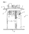
- FIG. 1 shows a conveyor unit 1 for use in a fuel tank 2 of a motor vehicle.
- the feed unit 1 consists of a flange 3 and a swirl pot 4.
- the flange 3 is designed so that it closes an opening 5 of the fuel tank 2, through which the feed unit 1 is inserted into the fuel tank 2.
- a fuel pump not shown, is arranged, which promotes fuel from the swirl pot 4 through the flange 3 to an internal combustion engine, not shown, of the motor vehicle.
- guides 13 are arranged, in each of which a support element 6 engages.
- Each support element 6 is surrounded by a helical spring 7.
- the coil springs 7 are supported on the flange 3 and on the guides 5 and cause in this way a bias of the baffle 4 against the bottom 8 of the fuel tank. 2
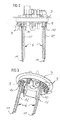
- FIGS. 2 and 3 show the flange 3 with the support elements 6.
- the support elements 6 To attach the support elements 6 has the flange bushes 9, in which the support elements 6 are pressed.
- the support elements 6 each have a collar 10 in the upper region, which is the insertion depth of the support elements 6 limited. At the same time, this ensures that each support element 6 is pressed in the same depth and thus the swirl pot is biased by the coil springs 7 against all latching hooks 11 at the lower end of the support elements 6 before the conveyor unit 1 is mounted in the fuel tank 2.
- the support elements 6 are made of polyamide. To avoid electrostatic charges carbon is added in the form of soot.
- the support elements 6 For mechanical reinforcement, the support elements 6 have axially extending webs 12. In addition, the webs 11 form a good guide for the coil springs.
Abstract
Description
Gegenstand der Erfindung ist eine Fördereinheit zum Fördern von Kraftstoff aus einem Kraftstoffbehälter zu einer Brennkraftmaschine eines Kraftfahrzeugs mit einer Kraftstoffpumpe, welche in einem Schwalltopf angeordnet ist und einem Flansch, welcher eine Öffnung des Kraftstoffbehälter verschließt, wobei der Schwalltopf mit dem Flansch über mindestens zwei Abstützelemente mit dem Schwalltopf verbunden ist.The invention relates to a delivery unit for conveying fuel from a fuel tank to an internal combustion engine of a motor vehicle with a fuel pump, which is arranged in a swirl pot and a flange which closes an opening of the fuel tank, wherein the swirl pot with the flange via at least two support elements connected to the swirl pot.
Derartige Fördereinheiten sind seit langem bekannt und somit Stand der Technik. Dazu ist es bekannt, die Abstützelemente als Metallrohre auszubilden. Die Abstützelemente werden mittels Presspassung in Aufnahmebuchsen im Flansch eingepresst. Der Schwalltopf besitzt an seinem Umfang entsprechende Führungen, in denen die Abstützelemente längsverschieblich geführt sind. Die Abstützelemente umgebende Spiralfedern, welche sich mit einem Ende am jeweiligen Abstützelement oder am Flansch und mit dem anderen Ende am Schwalltopf abstützen, bewirken, dass der Schwalltopf gegen den Boden des Kraftstoffbehälters vorgespannt wird. Aufgrund vorgegebener Sicherheitsbestimmungen müssen Metallteile mit einer Kapazität größer als 3 pF gegen statische Aufladungen abgesichert sein. Das bedeutet, dass die Metallrohre geerdet sein müssen, wodurch der Aufwand für die Fördereinheit steigt.Such conveyor units have long been known and thus state of the art. For this purpose it is known to form the support elements as metal pipes. The support elements are pressed by means of press fit in receiving bushes in the flange. The swirl pot has at its periphery corresponding guides in which the support elements are guided longitudinally displaceable. The supporting elements surrounding coil springs, which are supported at one end on the respective support member or on the flange and the other end of the swirl pot, cause the swirl pot is biased against the bottom of the fuel tank. Due to specified safety regulations, metal parts with a capacity greater than 3 pF must be protected against static charges. This means that the metal pipes must be earthed, which increases the cost of the conveyor unit.
Aus der
Der vorliegenden Erfindung liegt daher die Aufgabe zugrunde, eine Fördereinheit mit geringem Aufwand vorzusehen.The present invention is therefore based on the object to provide a conveyor unit with little effort.
Gelöst wird die Aufgabe dadurch, dass die Abstützelemente in Buchsen des Flansches eingepresst sind und aus einem kraftstoffbeständigen Kunststoff bestehen, wobei die Abstützelemente direkt mit dem Schwalltopf verbunden sind.The object is achieved in that the support elements are pressed into sockets of the flange and consist of a fuel-resistant plastic, wherein the support elements are connected directly to the surge pot.
Durch die Wahl eines kraftstoffbeständigen Kunststoffs als Material für die Abstützelemente besitzen diese eine Kapazität kleiner als 3 pF. Somit müssen diese Bauteile gemäß den vorgegebenen Sicherheitsbestimmungen nicht zusätzlich gegen statische Aufladungen gesichert sein. Eine Erdung der Abstützelemente kann daher entfallen, wodurch sich der Aufwand für die Fördereinheit verringert.By choosing a fuel-resistant plastic as the material for the support elements, they have a capacity of less than 3 pF. Thus, these components according to the safety regulations are not additionally secured against static charges. A grounding of the support elements can therefore be omitted, thereby reducing the cost of the delivery unit.
Für den Einsatz in kraftstoffhaltigen Umgebungen haben sich als Kunststoffe Polyoxymethylen oder Polyamid bewährt, die sich darüber hinaus durch eine gute Verarbeitung insbesondere mittels Spritzgießens auszeichnen.For use in fuel-containing environments have proven to be polyoxymethylene or polyamide as plastics, which are also characterized by good processing in particular by injection molding.
Zur weiteren Erhöhung der Sicherheit gegen elektrostatische Aufladungen, bzw. deren gefahrlose Ableitung ist es vorteilhaft, wenn der Kunststoff für die Abstützelemente Beimischungen von Kohlenstoff in Form von Ruß oder Nanotubes enthält.To further increase the safety against electrostatic charges, or their safe dissipation, it is advantageous if the plastic for the support elements contains admixtures of carbon in the form of carbon black or nanotubes.
Sofern der Schwalltopf und insbesondere die Führungen für die Abstützelemente ebenfalls aus Kunststoff bestehen, kann es bei einer Bewegung der Abstützelemente in den Führungen zu einer unerwünschten Geräuschentwicklung kommen. Eine derartige Geräuschentwicklung wird vermieden, wenn der Kunststoff für die Abstützelemente Beimischungen von Kreide enthält.If the baffle pot and in particular the guides for the support elements are also made of plastic, undesired noise may occur during movement of the support elements in the guides. Such noise is avoided when the plastic for the support elements contains admixtures of chalk.
Um eine ausreichende Stabilität der Abstützelemente bei geringen Querschnittsabmessungen zu erhalten, hat es sich als vorteilhaft herausgestellt die Abstützelemente mit einer entlang ihrer Längsachse verlaufende Profilierung zu versehen.In order to obtain a sufficient stability of the support elements with small cross-sectional dimensions, it has proven to be advantageous to provide the support elements with a profiling extending along their longitudinal axis.
Als Profile sind die unterschiedlichsten Formen denkbar. Neben Hohlprofilen haben sich aber auch Vollprofile bewährt. Ein geringer Materialeinsatz bei ausreichender Festigkeit wird gemäß einer vorteilhaften Ausgestaltung mit Abstützelementen erreicht, welche eine als Stege ausgebildete Profilierung aufweisen.As profiles the most different forms are conceivable. In addition to hollow sections but also solid profiles have proven. A low material usage with sufficient strength is achieved according to an advantageous embodiment with supporting elements which have a profile formed as webs.
Die Befestigung der Abstützelemente gestaltet sich besonders einfach, wenn die Abstützelemente an ihrem dem Schwalltopf zugewandten Ende zumindest einen nach radial außen gerichteten Rasthaken aufweisen. Beim ersten Einführen der Abstützelemente in die Führungen des Schwalltopfes wird der zumindest eine Rasthaken reversibel verformt, bis er die Führung passiert hat. Anschließend bewegt er sich in seine Ausgangslage, wodurch das jeweilige Abstützelement gegen ein Lösen aus der Führung gesichert ist. Auf diese Weise lassen sich die Abstützelemente besonders einfach montieren.The attachment of the support elements is particularly simple when the support elements at its end facing the swirl pot at least one directed radially outward Have latching hooks. During the first insertion of the support elements in the guides of the swirl pot, the at least one latching hook is reversibly deformed until it has passed the guide. Subsequently, it moves into its initial position, whereby the respective support element is secured against loosening from the guide. In this way, the support elements are particularly easy to assemble.
An einem Ausführungsbeispiel wird die Erfindung näher erläutert. Dabei zeigen
- Figur 1:
- eine erfindungsgemäße Fördereinheit und
Figur 2, 3:- den Flansch der Fördereinheit gemäß
Figur 1 .
- FIG. 1:
- a conveyor unit according to the invention and
- 2, 3:
- the flange of the liquid end according to
FIG. 1 ,
Die
Claims (7)
- Delivery unit for delivering fuel from a fuel tank (2) to an internal combustion engine of a motor vehicle, with a fuel pump which is arranged in a swirl pot (4), and a flange (3) which closes an opening (5) of the fuel tank, wherein the swirl pot is connected to the flange via at least two supporting elements (6), and wherein the supporting elements (6) are pressed into bushings (9) of the flange, characterized in that the supporting elements (6) consist of a fuel-resistant plastic material, the supporting elements (6) being connected directly to the swirl pot.
- Delivery unit according to Claim 1, characterized in that the supporting elements (6) consist of polyoxymethylene or polyamide.
- Delivery unit according to Claims 1 and 2, characterized in that the supporting elements (6) contain admixtures of carbon in the form of soot or nanotubes.
- Delivery unit according to at least one of the preceding Claims 1 to 3, characterized in that the supporting elements (6) consist of a chalk-filled plastic material.
- Delivery unit according to at least one of the preceding Claims 1 to 4, characterized in that the supporting elements (6) have a profiling running along their longitudinal axis.
- Delivery unit according to Claim 5, characterized in that the supporting elements (6) have a profiling designed as webs.
- Delivery unit according to at least one of the preceding Claims 1 to 6, characterized in that the supporting elements (6), at their end facing the swirl pot, have at least one radially outwardly directed latching hook.
Applications Claiming Priority (3)
| Application Number | Priority Date | Filing Date | Title |
|---|---|---|---|
| DE102007007597 | 2007-02-13 | ||
| DE102008005358A DE102008005358A1 (en) | 2007-02-13 | 2008-01-21 | delivery unit |
| PCT/EP2008/051149 WO2008098840A1 (en) | 2007-02-13 | 2008-01-30 | Delivery unit |
Publications (2)
| Publication Number | Publication Date |
|---|---|
| EP2002109A1 EP2002109A1 (en) | 2008-12-17 |
| EP2002109B1 true EP2002109B1 (en) | 2011-03-16 |
Family
ID=39597756
Family Applications (1)
| Application Number | Title | Priority Date | Filing Date |
|---|---|---|---|
| EP08708464A Expired - Fee Related EP2002109B1 (en) | 2007-02-13 | 2008-01-30 | Delivery unit |
Country Status (9)
| Country | Link |
|---|---|
| US (1) | US7819108B2 (en) |
| EP (1) | EP2002109B1 (en) |
| KR (1) | KR101097552B1 (en) |
| CN (1) | CN101542102B (en) |
| BR (1) | BRPI0803087A2 (en) |
| DE (2) | DE102008005358A1 (en) |
| ES (1) | ES2362555T3 (en) |
| RU (1) | RU2410563C2 (en) |
| WO (1) | WO2008098840A1 (en) |
Families Citing this family (6)
| Publication number | Priority date | Publication date | Assignee | Title |
|---|---|---|---|---|
| KR101321937B1 (en) * | 2012-03-13 | 2013-10-28 | 현담산업 주식회사 | Fuel pump module |
| DE102013220885B4 (en) | 2013-10-15 | 2019-05-09 | Continental Automotive Gmbh | Feed unit and method of manufacture |
| US9539893B2 (en) * | 2014-09-29 | 2017-01-10 | Spectra Premium Industries Inc. | Fuel delivery module for low-profile fuel tank |
| JP6695707B2 (en) * | 2016-02-19 | 2020-05-20 | 愛三工業株式会社 | Fuel supply device |
| KR20170112333A (en) * | 2016-03-31 | 2017-10-12 | 주식회사 케이엠에프 | Fuel pump filter apparatus and method with electro conductive |
| JP6992669B2 (en) | 2018-04-27 | 2022-01-13 | 株式会社デンソー | Fuel supply device |
Family Cites Families (24)
| Publication number | Priority date | Publication date | Assignee | Title |
|---|---|---|---|---|
| US5482444A (en) * | 1994-09-06 | 1996-01-09 | General Motors Corporation | Vibration isolating mounting for an electric fuel pump |
| JP3640001B2 (en) | 1996-04-01 | 2005-04-20 | 株式会社デンソー | Fuel supply device |
| WO1998040620A1 (en) * | 1997-03-11 | 1998-09-17 | Aisan Kogyo Kabushiki Kaisha | In-tank fuel filter improved to resist electrification |
| DE19843019C1 (en) * | 1998-09-19 | 2000-03-09 | Bosch Gmbh Robert | Fuel feed device for automobile engine fuel injection system has fuel filter housing and fuel tank provided with earth connection via electrically conductive pipe connections |
| DE19915258C1 (en) * | 1999-04-03 | 2000-12-07 | Bosch Gmbh Robert | Housing for a feed pump driven by an electric motor |
| AT5218U1 (en) * | 1999-09-27 | 2002-04-25 | Tesma Motoren Getriebetechnik | FUEL TANK |
| US6216671B1 (en) * | 1999-11-22 | 2001-04-17 | Delphi Technologies, Inc. | Modular fuel reservoir for motor vehicle |
| DE29922474U1 (en) * | 1999-12-22 | 2001-05-03 | Bosch Gmbh Robert | Fuel supply device for an internal combustion engine of a motor vehicle |
| JP2003172218A (en) * | 2001-12-06 | 2003-06-20 | Nissan Motor Co Ltd | Fuel feeding module attachment structure for fuel tank |
| JP2003286925A (en) * | 2002-03-27 | 2003-10-10 | Aisan Ind Co Ltd | Fuel feed device |
| JP3911434B2 (en) * | 2002-04-03 | 2007-05-09 | 愛三工業株式会社 | Reserve container unit |
| JP2003293875A (en) * | 2002-04-03 | 2003-10-15 | Aisan Ind Co Ltd | Reserve container unit |
| JP4243845B2 (en) | 2002-11-28 | 2009-03-25 | 株式会社デンソー | Fuel supply device |
| US6890190B1 (en) * | 2003-02-27 | 2005-05-10 | Siemens Vdo Automotive Corporation | Steel fuel flange with plastic strut mounts and grounded struts |
| US7074058B2 (en) * | 2003-02-27 | 2006-07-11 | Siemens Vdo Automotive Corporation | Steel fuel flange with plastic strut mounts |
| JP2004275839A (en) | 2003-03-13 | 2004-10-07 | Tosoh Corp | Porous material, production method therefor, and its application |
| JP3891350B2 (en) * | 2003-03-24 | 2007-03-14 | 株式会社デンソー | Fuel supply device |
| DE10356061B4 (en) * | 2003-12-01 | 2009-04-02 | Continental Automotive Gmbh | Device for holding a fuel pump in a fuel tank |
| FR2875858B1 (en) * | 2004-09-28 | 2010-10-22 | Marwal Systems | COMPOUND ASSEMBLY OF A PICKUP MODULE AND AN ACCESSORY INSERABLE IN A FUEL TANK OF A MOTOR VEHICLE |
| US7185682B2 (en) * | 2004-12-22 | 2007-03-06 | Visteon Global Technologies, Inc. | Fuel flange assembly for a vehicle fuel system |
| JP4269340B2 (en) * | 2004-12-27 | 2009-05-27 | 株式会社デンソー | Fuel supply device |
| US7527042B2 (en) * | 2005-04-05 | 2009-05-05 | Ti Group Automotive Systems, Llc | Electrostatic charge control for in-tank fuel module components |
| JP4356897B2 (en) | 2005-06-07 | 2009-11-04 | 株式会社デンソー | Fuel supply device |
| US7398769B2 (en) * | 2006-05-22 | 2008-07-15 | Continental Automotive Systems Us, Inc. | Electrostatic discharge solution for grounding struts and spring in fuel supply unit |
-
2008
- 2008-01-21 DE DE102008005358A patent/DE102008005358A1/en not_active Withdrawn
- 2008-01-30 KR KR1020087027113A patent/KR101097552B1/en not_active IP Right Cessation
- 2008-01-30 RU RU2008144579/06A patent/RU2410563C2/en not_active IP Right Cessation
- 2008-01-30 EP EP08708464A patent/EP2002109B1/en not_active Expired - Fee Related
- 2008-01-30 ES ES08708464T patent/ES2362555T3/en active Active
- 2008-01-30 BR BRPI0803087-1A patent/BRPI0803087A2/en not_active IP Right Cessation
- 2008-01-30 US US12/300,443 patent/US7819108B2/en not_active Expired - Fee Related
- 2008-01-30 DE DE502008002855T patent/DE502008002855D1/en active Active
- 2008-01-30 CN CN2008800002156A patent/CN101542102B/en not_active Expired - Fee Related
- 2008-01-30 WO PCT/EP2008/051149 patent/WO2008098840A1/en active Application Filing
Also Published As
| Publication number | Publication date |
|---|---|
| RU2008144579A (en) | 2010-05-20 |
| CN101542102A (en) | 2009-09-23 |
| US7819108B2 (en) | 2010-10-26 |
| ES2362555T3 (en) | 2011-07-07 |
| WO2008098840A1 (en) | 2008-08-21 |
| US20090165753A1 (en) | 2009-07-02 |
| EP2002109A1 (en) | 2008-12-17 |
| RU2410563C2 (en) | 2011-01-27 |
| BRPI0803087A2 (en) | 2011-08-30 |
| KR20090026126A (en) | 2009-03-11 |
| DE102008005358A1 (en) | 2008-08-14 |
| KR101097552B1 (en) | 2011-12-22 |
| DE502008002855D1 (en) | 2011-04-28 |
| CN101542102B (en) | 2012-07-04 |
Similar Documents
| Publication | Publication Date | Title |
|---|---|---|
| EP1971793B1 (en) | Vibration damper comprising a protection against stones | |
| EP2002109B1 (en) | Delivery unit | |
| EP1835144A2 (en) | Connection for a tube-shaped air guide element to a turbo charger | |
| DE102011056782A1 (en) | INTAKE MANIFOLD MODULE FOR PREVENTING FUEL LEAKAGE OF A VEHICLE AND MANUFACTURING METHOD THEREOF | |
| DE102010024903A1 (en) | Apparatus for resiliently supporting an engine and method of making the same | |
| DE102016200307A1 (en) | Spring plate for a vibration damper | |
| DE102009012946A1 (en) | Valve device for use as positive or negative pressure relief valve in e.g. fuel filter in motor vehicle, has complementary circular valve seat, translationally adjustable valve piston, valve disk and guiding element that are made of plastic | |
| WO2004091983A1 (en) | Deflecting device for a safety belt | |
| EP1934464B1 (en) | Feed unit | |
| EP2122153B1 (en) | Pump unit | |
| DE102012222878A1 (en) | Working cylinder for motor vehicle, has scraper ring that is integrated in stop ring | |
| DE19534411B4 (en) | Device for receiving a fuel assembly within a fuel tank | |
| DE102009020658A1 (en) | Coupling device for steering shaft of vehicle, has outer shaft enclosing inner shaft along axial direction in sections, and damping element molded into inner shaft and formed in external polygon and/or hexagon head shape | |
| DE102019217202A1 (en) | High pressure fuel pump for a fuel system of an internal combustion engine | |
| DE102007032057A1 (en) | Prefilter for a fuel delivery unit | |
| EP1712397B1 (en) | Device for supplying fuel | |
| DE19933046A1 (en) | Feed unit inside fuel tank, in which holding part has pump holding element and receiving part with at least one spring element | |
| DE10335045A1 (en) | delivery unit | |
| EP1988323B1 (en) | Fuel pump for installation inside a fuel container with an adapter | |
| DE102008009572A1 (en) | Bracket arrangement for vehicle seating, has two seating elements and bracket with bearing bolt, where two seating elements are arranged in area of bearing surface for decreasing friction of coating | |
| DE10339563A1 (en) | Belt guide for motor vehicle safety belt with displacement body has adapter with displacement body for limiting guide gap width and opening for attachment bolt; adapter is attached to edge of guide element | |
| DE102015215092A1 (en) | High-pressure fuel pump | |
| EP2886880B1 (en) | Furniture | |
| DE102013011409A1 (en) | Modular system for a plurality of Bauvaraianten a fuel delivery device of an internal combustion engine | |
| WO2009065751A1 (en) | Fuel pump |
Legal Events
| Date | Code | Title | Description |
|---|---|---|---|
| PUAI | Public reference made under article 153(3) epc to a published international application that has entered the european phase |
Free format text: ORIGINAL CODE: 0009012 |
|
| 17P | Request for examination filed |
Effective date: 20081007 |
|
| AK | Designated contracting states |
Kind code of ref document: A1 Designated state(s): AT BE BG CH CY CZ DE DK EE ES FI FR GB GR HR HU IE IS IT LI LT LU LV MC MT NL NO PL PT RO SE SI SK TR |
|
| AX | Request for extension of the european patent |
Extension state: AL BA MK RS |
|
| 17Q | First examination report despatched |
Effective date: 20090922 |
|
| RBV | Designated contracting states (corrected) |
Designated state(s): DE ES FR GB IT |
|
| GRAP | Despatch of communication of intention to grant a patent |
Free format text: ORIGINAL CODE: EPIDOSNIGR1 |
|
| DAX | Request for extension of the european patent (deleted) | ||
| GRAS | Grant fee paid |
Free format text: ORIGINAL CODE: EPIDOSNIGR3 |
|
| GRAA | (expected) grant |
Free format text: ORIGINAL CODE: 0009210 |
|
| AK | Designated contracting states |
Kind code of ref document: B1 Designated state(s): DE ES FR GB IT |
|
| REG | Reference to a national code |
Ref country code: GB Ref legal event code: FG4D Free format text: NOT ENGLISH |
|
| REF | Corresponds to: |
Ref document number: 502008002855 Country of ref document: DE Date of ref document: 20110428 Kind code of ref document: P |
|
| REG | Reference to a national code |
Ref country code: DE Ref legal event code: R096 Ref document number: 502008002855 Country of ref document: DE Effective date: 20110428 |
|
| REG | Reference to a national code |
Ref country code: ES Ref legal event code: FG2A Ref document number: 2362555 Country of ref document: ES Kind code of ref document: T3 Effective date: 20110707 |
|
| PLBE | No opposition filed within time limit |
Free format text: ORIGINAL CODE: 0009261 |
|
| STAA | Information on the status of an ep patent application or granted ep patent |
Free format text: STATUS: NO OPPOSITION FILED WITHIN TIME LIMIT |
|
| 26N | No opposition filed |
Effective date: 20111219 |
|
| REG | Reference to a national code |
Ref country code: DE Ref legal event code: R097 Ref document number: 502008002855 Country of ref document: DE Effective date: 20111219 |
|
| PGFP | Annual fee paid to national office [announced via postgrant information from national office to epo] |
Ref country code: IT Payment date: 20120123 Year of fee payment: 5 |
|
| PGFP | Annual fee paid to national office [announced via postgrant information from national office to epo] |
Ref country code: FR Payment date: 20130213 Year of fee payment: 6 Ref country code: ES Payment date: 20130128 Year of fee payment: 6 Ref country code: GB Payment date: 20130122 Year of fee payment: 6 Ref country code: DE Payment date: 20130131 Year of fee payment: 6 |
|
| REG | Reference to a national code |
Ref country code: DE Ref legal event code: R119 Ref document number: 502008002855 Country of ref document: DE |
|
| GBPC | Gb: european patent ceased through non-payment of renewal fee |
Effective date: 20140130 |
|
| REG | Reference to a national code |
Ref country code: DE Ref legal event code: R119 Ref document number: 502008002855 Country of ref document: DE Effective date: 20140801 |
|
| PG25 | Lapsed in a contracting state [announced via postgrant information from national office to epo] |
Ref country code: DE Free format text: LAPSE BECAUSE OF NON-PAYMENT OF DUE FEES Effective date: 20140801 |
|
| REG | Reference to a national code |
Ref country code: FR Ref legal event code: ST Effective date: 20140930 |
|
| PG25 | Lapsed in a contracting state [announced via postgrant information from national office to epo] |
Ref country code: FR Free format text: LAPSE BECAUSE OF NON-PAYMENT OF DUE FEES Effective date: 20140131 Ref country code: GB Free format text: LAPSE BECAUSE OF NON-PAYMENT OF DUE FEES Effective date: 20140130 |
|
| REG | Reference to a national code |
Ref country code: ES Ref legal event code: FD2A Effective date: 20151002 |
|
| PG25 | Lapsed in a contracting state [announced via postgrant information from national office to epo] |
Ref country code: ES Free format text: LAPSE BECAUSE OF NON-PAYMENT OF DUE FEES Effective date: 20140131 |
|
| PG25 | Lapsed in a contracting state [announced via postgrant information from national office to epo] |
Ref country code: IT Free format text: LAPSE BECAUSE OF NON-PAYMENT OF DUE FEES Effective date: 20140130 |