EP2002066B1 - Befestigungseinrichtung für bauelemente des trockenbaus - Google Patents
Befestigungseinrichtung für bauelemente des trockenbaus Download PDFInfo
- Publication number
- EP2002066B1 EP2002066B1 EP06828933A EP06828933A EP2002066B1 EP 2002066 B1 EP2002066 B1 EP 2002066B1 EP 06828933 A EP06828933 A EP 06828933A EP 06828933 A EP06828933 A EP 06828933A EP 2002066 B1 EP2002066 B1 EP 2002066B1
- Authority
- EP
- European Patent Office
- Prior art keywords
- fastening
- fastening device
- fastening element
- section
- legs
- Prior art date
- Legal status (The legal status is an assumption and is not a legal conclusion. Google has not performed a legal analysis and makes no representation as to the accuracy of the status listed.)
- Active
Links
- 238000010276 construction Methods 0.000 title claims abstract description 7
- 238000013016 damping Methods 0.000 claims abstract description 19
- 239000002184 metal Substances 0.000 claims abstract description 7
- 239000011324 bead Substances 0.000 claims description 5
- 239000000463 material Substances 0.000 claims description 5
- 230000001413 cellular effect Effects 0.000 claims description 4
- 229920001971 elastomer Polymers 0.000 claims description 4
- 238000009434 installation Methods 0.000 claims description 4
- 239000004793 Polystyrene Substances 0.000 claims description 3
- 239000006260 foam Substances 0.000 claims description 3
- 229920002223 polystyrene Polymers 0.000 claims description 3
- 239000000758 substrate Substances 0.000 description 3
- 230000005540 biological transmission Effects 0.000 description 2
- 229910000831 Steel Inorganic materials 0.000 description 1
- 238000005553 drilling Methods 0.000 description 1
- 239000000806 elastomer Substances 0.000 description 1
- 238000009413 insulation Methods 0.000 description 1
- 230000003014 reinforcing effect Effects 0.000 description 1
- 239000010959 steel Substances 0.000 description 1
Images


Classifications
-
- E—FIXED CONSTRUCTIONS
- E04—BUILDING
- E04B—GENERAL BUILDING CONSTRUCTIONS; WALLS, e.g. PARTITIONS; ROOFS; FLOORS; CEILINGS; INSULATION OR OTHER PROTECTION OF BUILDINGS
- E04B9/00—Ceilings; Construction of ceilings, e.g. false ceilings; Ceiling construction with regard to insulation
- E04B9/18—Means for suspending the supporting construction
Definitions
- the present invention relates to a fastening device for components of dry construction, in particular for C ceiling profiles, comprising a first fastening element with a U-shaped bent sheet metal profile having a bottom portion and two mounting legs,
- a known fastener is the Sparab vonr, which consists of a U-shaped bent sheet metal profile and having a bottom portion and two attached mounting leg With such a direct hanger example C ceiling profiles can be mounted at the desired height to a ceiling.
- a fastening device which is composed of two fastening elements, wherein an elastic damping element is arranged between the elements.
- Object of the present invention is a fastening device for components of drywall specify which allows a reduction of the sound transmission and is easy to produce.
- This object is achieved in a fastening device mentioned above by recesses in the support portion through which extend the mounting legs of the first fastener.
- the elastic damping element consists of a cellular material, in particular of foam.
- damping element consists wholly or partly of rubber and / or polystyrene.
- the height of the elastic damping element before installation is between 2 and 8 mm, in particular between 5 and 8 mm. After installation, the damping element may be deformed by the forces occurring and then have a lower height.
- the second fastening element is formed by a U-shaped, a U-bottom and two U-legs having sheet, wherein the U-bottom forms the support portion.
- the determination on a substrate is particularly simple when each of the U-legs of the second fastener one of the connecting portions is arranged.
- the stability of the fastening device is improved by the fact that the second fastening element has at least one stiffening bead in the region of the support section.
- the first fastening element has the form of a direct suspender.
- the figures show embodiments of the fastening device according to the invention, which are suitable for components of the drywall.
- the fastening device comprises a first fastening element 1 and a second fastening element 2.
- the first fastener 1 has a U-shaped bent sheet metal profile with a bottom portion 3 and two provided on this fastening legs 4, 4 '.
- the first fastener has the form of a direct suspender. In which an elongated, approximately rectangular shape having bottom portion 3, two extending in the longitudinal direction downwardly facing stiffening beads 5 are formed to increase its stability. Along the central axis, the bottom portion has an elongated opening 6.
- the mounting legs 4, 4 ' are each provided with a plurality of holes 7, which are arranged distributed on the mounting legs 4, 4' over the height thereof.
- the fastening device furthermore has the second fastening element 2 designed as a separate component, which has a connecting section 9 on both sides.
- These connecting portions 9 are each provided with a bore 10 to be fixed to a substrate with a fastener such as a screw (not shown).
- the second fastening element 2 has a support section 11, which supports the bottom section 3 of the first fastening element 1.
- the second fastening element 2 is formed by a U-bottom 12 and two U-legs 13 having sheet metal.
- the U-bottom 12 forms the support portion 11 on the U-legs 13 of the second fastener 2 each one of the connecting portions 9 is folded.
- Fig. 4 clearly shows the arrangement of one of these recesses 14, which has an elongated shape.
- an identically formed recess 14 is provided, which in the illustration in Fig. 4 is covered by the U-leg 13 and the connecting portion 9.
- the recesses 14 are formed and adapted to the first fastening element 1, that the fastening legs 4, 4 'can extend through the recesses 14.
- the second fastening element 2 in the region of the support portion 11 have stiffening beads.
- an elastic damping element 15 is arranged between the support portion 11 of the second fastening element 2 and the bottom portion 3 of the first fastening element 1.
- This consists in the illustrated embodiment of a cellular material such as foam, which has elastic and damping properties.
- the damping element 15 may also consist of a non-cellular material with elastic damping properties.
- a material for the damping element is particularly preferably elastomer, for example rubber, or polystyrene into consideration.
- the first and second fastening element 1, 2 are preferably made of galvanized sheet steel.
- the fastening device according to the invention is intended for components of drywall.
- C ceiling profiles can thus be set in a simple and reliable manner to a substrate.
- the two-part construction of the fastening device with intermediate damping element allows an effective reduction of sound transmission. Nevertheless, the fastening device is easy to use and can be installed in a time-saving manner.
Landscapes
- Engineering & Computer Science (AREA)
- Architecture (AREA)
- Physics & Mathematics (AREA)
- Electromagnetism (AREA)
- Civil Engineering (AREA)
- Structural Engineering (AREA)
- Building Environments (AREA)
- Joining Of Building Structures In Genera (AREA)
- Vibration Prevention Devices (AREA)
- Conveying And Assembling Of Building Elements In Situ (AREA)
- Rod-Shaped Construction Members (AREA)
- Buildings Adapted To Withstand Abnormal External Influences (AREA)
- Connection Of Plates (AREA)
Description
- Die vorliegende Erfindung betrifft eine Befestigungseinrichtung für Bauelemente des Trockenbaus, insbesondere für C-Deckenprofile, umfassend ein erstes Befestigungselement mit einem U-förmig gebogenen Blechprofil, das einen Bodenabschnitt und zwei Befestigungsschenkel aufweist,
- Zur Befestigung von Bauelementen werden im Trockenbau verschiedene Befestigungselemente verwendet. Ein bekanntes Befestigungselement ist der Direktabhänger, welcher aus einem U-förmig gebogenen Blechprofil besteht und einen Bodenabschnitt und zwei daran befestigte Befestigungsschenkel aufweist Mit einem solchen Direktabhänger können beispielsweise C-Deckenprofile in der gewünschten Höhe an einer Decke befestigt werden.
- Nachteilig ist bei einem solchen Direktabhänger, dass in einigen Anwendungsfällen durch die Konstruktion Schall in einem größeren Umfang als gewünscht übertragen wird.
- Aus der
GB 2 332 004 A - Aufgabe der vorliegenden Erfindung ist es, eine Befestigungseinrichtung für Bauelemente des Trockenbaus anzugeben, welche eine Reduzierung der Schallübertragung ermöglicht und einfach herstellbar ist.
- Diese Aufgabe wird bei einer eingangs genannten Befestigungseinrichtung gelöst durch Ausnehmungen in dem Stützabschnitt, durch die sich die Befestigungsschenkel des ersten Befestigungselements erstrecken.
- Mit dieser Gestaltung kann eine erheblich verbesserte Schalldämmung erreicht werden. Schwingungen werden in einem erheblichen Umfang isoliert und nicht durch die Befestigungseinrichtung auf den Untergrund übertragen.
- Eine besonders gute Schalldämmung kann dann erreicht werden, wenn das elastische Dämpfungselement aus einem zelligen Material, insbesondere aus Schaumstoff besteht.
- Dies gilt auch dann, wenn das Dämpfungselement ganz oder teilweise aus Gummi und/ oder Polystyrol besteht.
- Es hat sich bewährt, wenn die Höhe des elastischen Dämpfungselements vor dem Einbau zwischen 2 und 8 mm, insbesondere zwischen 5 und 8 mm liegt. Nach Einbau kann das Dämpfungselement durch die auftretenden Kräfte verformt sein und dann eine geringere Höhe aufweisen.
- Gemäß einer besonders vorteilhaften Ausgestaltung ist das zweite Befestigungselement von einem U-förmigen, einen U-Boden und zwei U-Schenkel aufweisenden Blech gebildet, wobei der U-Boden den Stützabschnitt bildet.
- Die Festlegung an einem Untergrund ist dann besonders einfach, wenn an den U-Schenkeln des zweiten Befestigungselements jeweils einer der Verbindungsabschnitte angeordnet ist.
- Die Stabilität der Befestigungseinrichtung wird dadurch verbessert, dass das zweite Befestigungselement im Bereich des Stützabschnitts wenigstens eine Versteifungssicke aufweist.
- In vorteilhafter Weise hat das erste Befestigungselement die Form eines Direktabhängers.
- Weitere Ziele, Merkmale, Vorteile und Anwendungsmöglichkeiten der vorliegenden Erfindung ergeben sich aus der nachfolgenden Beschreibung von Ausführungsbeispielen anhand der Zeichnungen. Dabei bilden alle beschriebenen und/oder bildlich dargestellten Merkmale für sich oder in beliebiger Kombination den Gegenstand der Erfindung, auch unabhängig von der Zusammenfassung in einzelnen Ansprüchen oder deren Rückbeziehung.
- Es zeigen:
- Figur 1:
- eine perspektivische Darstellung einer erfindungsgemäßen Befestigungseinrichtung nach einer ersten Ausführungsform;
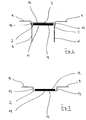
- Figur 2:
- eine Seitenansicht einer Befestigungseinrichtung nach einer zweiten Ausführungsform;
- Figur 3:
- eine Seitenansicht des zweiten Befestigungselements aus
Figur 2 ; - Figur 4:
- eine perspektivische Darstellung des zweiten Befestigungselements aus
Figur 2 mit abgenommenen Dämpfungselement; - Figur 5:
- eine perspektivische Darstellung eines ersten Befestigungselements;
- Die Figuren zeigen Ausführungsformen der erfindungsgemäßen Befestigungseinrichtung, welche für Bauelemente des Trockenbaus geeignet sind. Die Befestigungseinrichtung umfasst ein erstes Befestigungselement 1 und ein zweites Befestigungselement 2.
- Das erste Befestigungselement 1 weist ein U-förmig gebogenes Blechprofil mit einem Bodenabschnitt 3 und zwei an diesem vorgesehenen Befestigungsschenkeln 4, 4' auf. Das erste Befestigungselement hat dabei die Form eines Direktabhängers. In dem eine längliche, in etwa rechteckige Form aufweisenden Bodenabschnitt 3 sind zur Erhöhung von dessen Stabilität zwei sich in Längsrichtung erstreckende nach unten weisende Versteifungssicken 5 ausgeformt. Entlang der Mittelachse weist der Bodenabschnitt eine längliche Öffnung 6 auf.
- Die Befestigungsschenkel 4, 4' sind jeweils mit einer Vielzahl von Löchern 7 versehen, welche an den Befestigungsschenkeln 4, 4' über deren Höhe verteilt angeordnet sind.
- In den
Fig. 1 und5 ist gut erkennbar, dass die Befestigungsschenkel 4, 4' darüber hinaus an ihren äußeren Kanten eine Reihe von V-förmigen Einschnitten 8 aufweisen. - Die Befestigungseinrichtung weist darüber hinaus das als separates Bauteil ausgebildete zweite Befestigungselement 2 auf, das beidseitig jeweils einen Verbindungsabschnitt 9 hat. Diese Verbindungsabschnitte 9 sind jeweils mit einer Bohrung 10 versehen, um mit einem Befestigungselement, wie einer Schraube (nicht dargestellt) an einem Untergrund festgelegt zu werden.
- Zwischen den Verbindungsabschnitten 9 weist das zweite Befestigungselement 2 einen Stützabschnitt 11 auf, welcher den Bodenabschnitt 3 des ersten Befestigungselements 1 trägt.
- Wie in den Figuren gut erkennbar ist, wird das zweite Befestigungselement 2 von einem einen U-Boden 12 und zwei U-Schenkel 13 aufweisenden Blech gebildet. Dabei bildet der U-Boden 12 den Stützabschnitt 11. An den U-Schenkeln 13 des zweiten Befestigungselements 2 ist jeweils einer der Verbindungsabschnitte 9 abgekantet.
- In dem Stützabschnitt 11 sind zwei Ausnehmungen 14 ausgebildet.
Fig. 4 zeigt deutlich die Anordnung einer dieser Ausnehmungen 14, welche eine längliche Form hat. An der gegenüberliegenden Seite des Stützabschnitts 11 ist eine identisch ausgebildete Ausnehmung 14 vorgesehen, welche bei der Darstellung inFig. 4 durch den U-Schenkel 13 bzw. den Verbindungsabschnitt 9 verdeckt wird. - Die Ausnehmungen 14 sind derart ausgebildet und an das erste Befestigungselement 1 angepasst, dass sich die Befestigungsschenkel 4, 4' durch die Ausnehmungen 14 erstrecken können.
- Anders als dargestellt, kann das zweite Befestigungselement 2 im Bereich des Stützabschnitts 11 Versteifungssicken aufweisen. Zwischen dem Stützabschnitt 11 des zweiten Befestigungselements 2 und dem Bodenabschnitt 3 des ersten Befestigungselements 1 ist ein elastisches Dämpfungselement 15 angeordnet. Dieses besteht bei der dargestellten Ausführungsform aus einem zelligen Material wie Schaumstoff, welches elastische und Dämpfungseigenschaften aufweist. Das Dämpfungselement 15 kann aber auch aus einem nichtzelligen Material mit elastischen dämpfenden Eigenschaften bestehen. Als Material für das Dämpfungselement kommt dabei besonders bevorzugt Elastomer, z.B. Gummi, oder auch Polystyrol in Betracht.
- Es hat sich weiterhin bewährt, wenn das elastische Dämpfungselement vor dem Einbau zwischen 2 und 8 mm, insbesondere zwischen 5 und 8 mm hoch ist.
- Das erste und zweite Befestigungselement 1, 2 bestehen vorzugsweise aus verzinktem Stahlblech.
- Die erfindungsgemäße Befestigungseinrichtung ist für Bauelemente des Trockenbaus bestimmt. Insbesondere C-Deckenprofile können damit auf einfache und zuverlässige Weise an einem Untergrund festgelegt werden. Der zweiteilige Aufbau der Befestigungseinrichtung mit dazwischenliegendem Dämpfungselement ermöglicht dabei eine wirksame Reduktion der Schallübertragung. Dennoch ist die Befestigungseinrichtung einfach in der Handhabung und kann zeitsparend montiert werden.
-
- 1
- erstes Befestigungselement
- 2
- zweites Befestigungselement
- 3
- Bodenabschnitt
- 4, 4'
- Befestigungsschenkel
- 5
- Versteifungssicke
- 6
- Öffnung
- 7
- Loch
- 8
- V-förmige Einschnitte
- 9
- Verbindungsabschnitt
- 10
- Bohrung
- 11
- Stützabschnitt
- 12
- U-Boden
- 13
- U-Schenkel
- 14
- Ausnehmung
- 15
- elastisches Dämpfungselement
Claims (8)
- Befestigungseinrichtung für Bauelemente des Trockenbaus, insbesondere für C-Deckenprofile, umfassend ein erstes Befestigungselement (1) mit einem U-förmig gebogenen Blechprofil, das einen Bodenabschnitt (3) und zwei Befestigungsschenkel (4, 4') aufweist und ein zweites Befestigungselement (2), welches wenigstens einen Verbindungsabschnitt (9) zur Festlegung an einem Untergrund aufweist, wobei das zweite Befestigungselement (2) einen Stützabschnitt (11) für den Bodenabschnitt (3) des ersten Befestigungselements (1) aufweist, und wobei zwischen Stützabschnitt (11) und Bodenabschnitt (3) ein elastisches Dämpfungselement (15) angeordnet ist, dadurch gekennzeichnet, dass der Stützabschnitt (11) Ausnehmungen aufweist, durch die sich die Befestigungsschenkel (4, 4') des ersten Befestigungselements (1) erstrecken.
- Befestigungseinrichtung nach Anspruch 1, dadurch gekennzeichnet, dass das elastische Dämpfungselement (15) aus einem zelligen Material, insbesondere Schaumstoff besteht.
- Befestigungseinrichtung nach Anspruch 1 oder 2, dadurch gekennzeichnet, dass das Dämpfungselement (15) ganz oder teilweise aus Gummi und/oder Polystyrol besteht.
- Befestigungseinrichtung nach einem der Ansprüche 1 bis 3, dadurch gekennzeichnet, dass die Höhe des elastischen Dämpfungselements (15) vor dem Einbau zwischen 2 und 8 mm, insbesondere zwischen 5 und 8 mm liegt.
- Befestigungseinrichtung nach einem der Ansprüche 1 bis 4, dadurch gekennzeichnet, dass das zweite Befestigungselement (2) von einem U-förmigen, einen U-Boden (12) und zwei U-Schenkel (13) aufweisenden Blech gebildet ist, wobei der U-Boden (12) den Stützabschnitt (11) bildet.
- Befestigungseinrichtung nach Anspruch 5, dadurch gekennzeichnet, dass an den U-Schenkeln (13) des zweiten Befestigungselements (2) jeweils einer der Verbindungsabschnitte (9) angeordnet ist.
- Befestigungseinrichtung nach einem der Ansprüche 1 bis 6, dadurch gekennzeichnet, dass das zweite Befestigungselement (2) im Bereich des Stützabschnitts (11) wenigstens eine Versteifungssicke aufweist.
- Befestigungseinrichtung nach einem der Ansprüche 1 bis 7, dadurch gekennzeichnet, dass das erste Befestigungselement (1) die Form eines Direktabhängers aufweist.
Priority Applications (2)
| Application Number | Priority Date | Filing Date | Title |
|---|---|---|---|
| SI200631183T SI2002066T1 (sl) | 2006-04-05 | 2006-11-07 | Priprava za pritrjevanje gradbenih konstrukcijskih elementov |
| PL06828933T PL2002066T3 (pl) | 2006-04-05 | 2006-11-07 | Urządzenie mocujące dla elementów budowlanych suchej zabudowy |
Applications Claiming Priority (2)
| Application Number | Priority Date | Filing Date | Title |
|---|---|---|---|
| DE202006005678U DE202006005678U1 (de) | 2006-04-05 | 2006-04-05 | Befestigungseinrichtung für Bauelemente des Trockenbaus |
| PCT/EP2006/010637 WO2007112773A1 (de) | 2006-04-05 | 2006-11-07 | Befestigungseinrichtung für bauelemente des trockenbaus |
Publications (2)
| Publication Number | Publication Date |
|---|---|
| EP2002066A1 EP2002066A1 (de) | 2008-12-17 |
| EP2002066B1 true EP2002066B1 (de) | 2011-09-14 |
Family
ID=36643708
Family Applications (1)
| Application Number | Title | Priority Date | Filing Date |
|---|---|---|---|
| EP06828933A Active EP2002066B1 (de) | 2006-04-05 | 2006-11-07 | Befestigungseinrichtung für bauelemente des trockenbaus |
Country Status (10)
| Country | Link |
|---|---|
| EP (1) | EP2002066B1 (de) |
| AT (1) | ATE524623T1 (de) |
| DE (1) | DE202006005678U1 (de) |
| DK (1) | DK2002066T3 (de) |
| ES (1) | ES2372615T3 (de) |
| HR (1) | HRP20110871T1 (de) |
| PL (1) | PL2002066T3 (de) |
| RS (1) | RS52052B (de) |
| SI (1) | SI2002066T1 (de) |
| WO (1) | WO2007112773A1 (de) |
Families Citing this family (3)
| Publication number | Priority date | Publication date | Assignee | Title |
|---|---|---|---|---|
| DE202006009764U1 (de) | 2006-06-20 | 2006-09-21 | Richter-System Gmbh & Co. Kg | Verbindungselement für C-Profile mit Ausgleichsmittel und Anordnung |
| ES2611972A1 (es) * | 2015-11-10 | 2017-05-11 | Maiztarkoetxea S.L. | Dispositivo de suspensión anti-vibratoria de paneles de pared y techo |
| DE102018132181A1 (de) * | 2018-12-13 | 2020-06-18 | Protektorwerk Florenz Maisch Gmbh & Co. Kg | Profil |
Family Cites Families (5)
| Publication number | Priority date | Publication date | Assignee | Title |
|---|---|---|---|---|
| FR1001774A (fr) * | 1949-12-02 | 1952-02-27 | Dispositif de suspension isolant et anti-vibratile pour plafonds suspendus, utilisé dans l'industrie du bâtiment | |
| FR2711695B1 (fr) * | 1993-10-21 | 1995-12-22 | Knauf Cie Platres | Suspente pour profilé de grande portée, notamment pour la réalisation de faux-plafonds. |
| GB2314351B (en) * | 1996-05-15 | 2000-12-13 | Instafibre Ltd | Supports for floor, wall or ceiling claddings |
| GB2332004B (en) * | 1997-12-02 | 2002-04-10 | Instafibre Ltd | Resilient support system for walls |
| BE1016313A3 (nl) * | 2004-11-10 | 2006-07-04 | Composite Damping Material Nv | Montage-element voor plafond-, wand- en vloerplaten. |
-
2006
- 2006-04-05 DE DE202006005678U patent/DE202006005678U1/de not_active Expired - Lifetime
- 2006-11-07 EP EP06828933A patent/EP2002066B1/de active Active
- 2006-11-07 RS RS20110555A patent/RS52052B/en unknown
- 2006-11-07 SI SI200631183T patent/SI2002066T1/sl unknown
- 2006-11-07 PL PL06828933T patent/PL2002066T3/pl unknown
- 2006-11-07 AT AT06828933T patent/ATE524623T1/de active
- 2006-11-07 DK DK06828933.9T patent/DK2002066T3/da active
- 2006-11-07 WO PCT/EP2006/010637 patent/WO2007112773A1/de active Application Filing
- 2006-11-07 ES ES06828933T patent/ES2372615T3/es active Active
-
2011
- 2011-11-22 HR HR20110871T patent/HRP20110871T1/hr unknown
Also Published As
| Publication number | Publication date |
|---|---|
| DK2002066T3 (da) | 2011-12-19 |
| PL2002066T3 (pl) | 2012-02-29 |
| WO2007112773A1 (de) | 2007-10-11 |
| DE202006005678U1 (de) | 2006-06-14 |
| ES2372615T3 (es) | 2012-01-24 |
| SI2002066T1 (sl) | 2012-01-31 |
| HRP20110871T1 (hr) | 2011-12-31 |
| ATE524623T1 (de) | 2011-09-15 |
| RS52052B (en) | 2012-04-30 |
| EP2002066A1 (de) | 2008-12-17 |
Similar Documents
| Publication | Publication Date | Title |
|---|---|---|
| DE102008009608A1 (de) | Einrichtung mit einem Flächenelement und einer Klemmeinrichtung | |
| EP1288387B1 (de) | Profilierte Montageschiene | |
| DE102005016175A1 (de) | C-Profil | |
| EP2022902A2 (de) | Winkelverbinder | |
| EP1866492B1 (de) | C-profil und trennwand mit c-profil | |
| EP2035635B1 (de) | Verbindungselement für c-profile mit ausgleichsmittel und anordnung | |
| EP2002066B1 (de) | Befestigungseinrichtung für bauelemente des trockenbaus | |
| EP2024582B1 (de) | Profil aus Blech für den Trockenbau | |
| EP2333215B1 (de) | Führungselement für eine Schiebetür, insbesondere eine Ganzglasschiebetür | |
| DE202019101409U1 (de) | Profilsystem zur Bildung eines Untertragrahmens für die Aufnahme von Bodenbelägen und Anschlusselement | |
| EP3772443B1 (de) | Schienenfahrzeug mit mindestens einem fussbodenaufbau | |
| DE202008008405U1 (de) | Verbindungsbeschlag | |
| AT524008A1 (de) | Winkelverbinder | |
| DE102018005072A1 (de) | Befestigungselement zur Montage einer Fassadenpaneele | |
| DE102018107020A1 (de) | Haltesystem für eine Kabeltrasse | |
| DE102009006848B4 (de) | Radiallager | |
| DE202019103489U1 (de) | Tragschiene für ein Traggitter einer abgehängten Decke | |
| DE202008013470U1 (de) | Aufnahmeleiste für ein Flächenelement | |
| DE102020131596A1 (de) | Ankerschiene | |
| DE202022101269U1 (de) | Befestigungssystem und Abdeckeinheit | |
| DE202012103814U1 (de) | Wandanker | |
| DE202019107234U1 (de) | Haltekörper zur Ausbildung einer Tragschiene für ein Tragegitter einer abgehängten Decke bzw. Tragschiene mit Haltekörper | |
| DE202011050906U1 (de) | Wand- oder Deckenverkleidung, umfassend zumindest zwei Paneele | |
| EP2241697A2 (de) | Deckenabhänger | |
| DE102017122961A1 (de) | Montageschiene |
Legal Events
| Date | Code | Title | Description |
|---|---|---|---|
| PUAI | Public reference made under article 153(3) epc to a published international application that has entered the european phase |
Free format text: ORIGINAL CODE: 0009012 |
|
| 17P | Request for examination filed |
Effective date: 20081013 |
|
| AK | Designated contracting states |
Kind code of ref document: A1 Designated state(s): AT BE BG CH CY CZ DE DK EE ES FI FR GB GR HU IE IS IT LI LT LU LV MC NL PL PT RO SE SI SK TR |
|
| AX | Request for extension of the european patent |
Extension state: AL BA HR MK RS |
|
| 17Q | First examination report despatched |
Effective date: 20100325 |
|
| GRAP | Despatch of communication of intention to grant a patent |
Free format text: ORIGINAL CODE: EPIDOSNIGR1 |
|
| RTI1 | Title (correction) |
Free format text: FASTENING DEVICE FOR STRUCTURAL CONSTRUCTION UNITS |
|
| GRAS | Grant fee paid |
Free format text: ORIGINAL CODE: EPIDOSNIGR3 |
|
| GRAA | (expected) grant |
Free format text: ORIGINAL CODE: 0009210 |
|
| AK | Designated contracting states |
Kind code of ref document: B1 Designated state(s): AT BE BG CH CY CZ DE DK EE ES FI FR GB GR HU IE IS IT LI LT LU LV MC NL PL PT RO SE SI SK TR |
|
| AX | Request for extension of the european patent |
Extension state: AL BA HR MK RS |
|
| REG | Reference to a national code |
Ref country code: GB Ref legal event code: FG4D Free format text: NOT ENGLISH |
|
| REG | Reference to a national code |
Ref country code: CH Ref legal event code: EP |
|
| REG | Reference to a national code |
Ref country code: IE Ref legal event code: FG4D Free format text: LANGUAGE OF EP DOCUMENT: GERMAN |
|
| REG | Reference to a national code |
Ref country code: DE Ref legal event code: R096 Ref document number: 502006010196 Country of ref document: DE Effective date: 20111110 |
|
| REG | Reference to a national code |
Ref country code: HR Ref legal event code: TUEP Ref document number: P20110871 Country of ref document: HR |
|
| REG | Reference to a national code |
Ref country code: RO Ref legal event code: EPE |
|
| REG | Reference to a national code |
Ref country code: NL Ref legal event code: T3 |
|
| REG | Reference to a national code |
Ref country code: DK Ref legal event code: T3 |
|
| REG | Reference to a national code |
Ref country code: HR Ref legal event code: T1PR Ref document number: P20110871 Country of ref document: HR |
|
| REG | Reference to a national code |
Ref country code: ES Ref legal event code: FG2A Ref document number: 2372615 Country of ref document: ES Kind code of ref document: T3 Effective date: 20120124 |
|
| PG25 | Lapsed in a contracting state [announced via postgrant information from national office to epo] |
Ref country code: SE Free format text: LAPSE BECAUSE OF FAILURE TO SUBMIT A TRANSLATION OF THE DESCRIPTION OR TO PAY THE FEE WITHIN THE PRESCRIBED TIME-LIMIT Effective date: 20110914 Ref country code: FI Free format text: LAPSE BECAUSE OF FAILURE TO SUBMIT A TRANSLATION OF THE DESCRIPTION OR TO PAY THE FEE WITHIN THE PRESCRIBED TIME-LIMIT Effective date: 20110914 Ref country code: LT Free format text: LAPSE BECAUSE OF FAILURE TO SUBMIT A TRANSLATION OF THE DESCRIPTION OR TO PAY THE FEE WITHIN THE PRESCRIBED TIME-LIMIT Effective date: 20110914 |
|
| PGFP | Annual fee paid to national office [announced via postgrant information from national office to epo] |
Ref country code: CH Payment date: 20111124 Year of fee payment: 6 |
|
| LTIE | Lt: invalidation of european patent or patent extension |
Effective date: 20110914 |
|
| PG25 | Lapsed in a contracting state [announced via postgrant information from national office to epo] |
Ref country code: LV Free format text: LAPSE BECAUSE OF FAILURE TO SUBMIT A TRANSLATION OF THE DESCRIPTION OR TO PAY THE FEE WITHIN THE PRESCRIBED TIME-LIMIT Effective date: 20110914 Ref country code: CY Free format text: LAPSE BECAUSE OF FAILURE TO SUBMIT A TRANSLATION OF THE DESCRIPTION OR TO PAY THE FEE WITHIN THE PRESCRIBED TIME-LIMIT Effective date: 20110914 |
|
| REG | Reference to a national code |
Ref country code: PL Ref legal event code: T3 |
|
| REG | Reference to a national code |
Ref country code: SK Ref legal event code: T3 Ref document number: E 10760 Country of ref document: SK |
|
| REG | Reference to a national code |
Ref country code: GR Ref legal event code: EP Ref document number: 20110402929 Country of ref document: GR Effective date: 20120206 |
|
| PGFP | Annual fee paid to national office [announced via postgrant information from national office to epo] |
Ref country code: BE Payment date: 20111122 Year of fee payment: 6 |
|
| REG | Reference to a national code |
Ref country code: IE Ref legal event code: FD4D |
|
| PG25 | Lapsed in a contracting state [announced via postgrant information from national office to epo] |
Ref country code: IE Free format text: LAPSE BECAUSE OF FAILURE TO SUBMIT A TRANSLATION OF THE DESCRIPTION OR TO PAY THE FEE WITHIN THE PRESCRIBED TIME-LIMIT Effective date: 20110914 Ref country code: IS Free format text: LAPSE BECAUSE OF FAILURE TO SUBMIT A TRANSLATION OF THE DESCRIPTION OR TO PAY THE FEE WITHIN THE PRESCRIBED TIME-LIMIT Effective date: 20120114 |
|
| PG25 | Lapsed in a contracting state [announced via postgrant information from national office to epo] |
Ref country code: PT Free format text: LAPSE BECAUSE OF FAILURE TO SUBMIT A TRANSLATION OF THE DESCRIPTION OR TO PAY THE FEE WITHIN THE PRESCRIBED TIME-LIMIT Effective date: 20120116 Ref country code: EE Free format text: LAPSE BECAUSE OF FAILURE TO SUBMIT A TRANSLATION OF THE DESCRIPTION OR TO PAY THE FEE WITHIN THE PRESCRIBED TIME-LIMIT Effective date: 20110914 |
|
| PGFP | Annual fee paid to national office [announced via postgrant information from national office to epo] |
Ref country code: BG Payment date: 20111124 Year of fee payment: 6 |
|
| PG25 | Lapsed in a contracting state [announced via postgrant information from national office to epo] |
Ref country code: MC Free format text: LAPSE BECAUSE OF NON-PAYMENT OF DUE FEES Effective date: 20111130 |
|
| PLBE | No opposition filed within time limit |
Free format text: ORIGINAL CODE: 0009261 |
|
| STAA | Information on the status of an ep patent application or granted ep patent |
Free format text: STATUS: NO OPPOSITION FILED WITHIN TIME LIMIT |
|
| REG | Reference to a national code |
Ref country code: HU Ref legal event code: AG4A Ref document number: E013146 Country of ref document: HU |
|
| PGFP | Annual fee paid to national office [announced via postgrant information from national office to epo] |
Ref country code: HU Payment date: 20111105 Year of fee payment: 6 |
|
| 26N | No opposition filed |
Effective date: 20120615 |
|
| REG | Reference to a national code |
Ref country code: DE Ref legal event code: R082 Ref document number: 502006010196 Country of ref document: DE Representative=s name: REISER & PARTNER PATENTANWAELTE, DE Ref country code: DE Ref legal event code: R082 Ref document number: 502006010196 Country of ref document: DE Representative=s name: REISER & PARTNER PATENTANWAELTE MBB, DE |
|
| REG | Reference to a national code |
Ref country code: DE Ref legal event code: R097 Ref document number: 502006010196 Country of ref document: DE Effective date: 20120615 |
|
| BERE | Be: lapsed |
Owner name: RICHTER-SYSTEM G.M.B.H. & CO. KG Effective date: 20121130 |
|
| PG25 | Lapsed in a contracting state [announced via postgrant information from national office to epo] |
Ref country code: LU Free format text: LAPSE BECAUSE OF NON-PAYMENT OF DUE FEES Effective date: 20111107 |
|
| REG | Reference to a national code |
Ref country code: CH Ref legal event code: PL |
|
| GBPC | Gb: european patent ceased through non-payment of renewal fee |
Effective date: 20121107 |
|
| PG25 | Lapsed in a contracting state [announced via postgrant information from national office to epo] |
Ref country code: LI Free format text: LAPSE BECAUSE OF NON-PAYMENT OF DUE FEES Effective date: 20121130 Ref country code: CH Free format text: LAPSE BECAUSE OF NON-PAYMENT OF DUE FEES Effective date: 20121130 |
|
| PG25 | Lapsed in a contracting state [announced via postgrant information from national office to epo] |
Ref country code: BE Free format text: LAPSE BECAUSE OF NON-PAYMENT OF DUE FEES Effective date: 20121130 Ref country code: HU Free format text: LAPSE BECAUSE OF NON-PAYMENT OF DUE FEES Effective date: 20121108 |
|
| PG25 | Lapsed in a contracting state [announced via postgrant information from national office to epo] |
Ref country code: GB Free format text: LAPSE BECAUSE OF NON-PAYMENT OF DUE FEES Effective date: 20121107 |
|
| PG25 | Lapsed in a contracting state [announced via postgrant information from national office to epo] |
Ref country code: BG Free format text: LAPSE BECAUSE OF NON-PAYMENT OF DUE FEES Effective date: 20121130 |
|
| REG | Reference to a national code |
Ref country code: HR Ref legal event code: ODRP Ref document number: P20110871 Country of ref document: HR Payment date: 20141030 Year of fee payment: 9 |
|
| PGFP | Annual fee paid to national office [announced via postgrant information from national office to epo] |
Ref country code: DK Payment date: 20141124 Year of fee payment: 9 |
|
| PGFP | Annual fee paid to national office [announced via postgrant information from national office to epo] |
Ref country code: SK Payment date: 20141104 Year of fee payment: 9 Ref country code: RO Payment date: 20141105 Year of fee payment: 9 Ref country code: CZ Payment date: 20141031 Year of fee payment: 9 Ref country code: ES Payment date: 20141120 Year of fee payment: 9 |
|
| PGFP | Annual fee paid to national office [announced via postgrant information from national office to epo] |
Ref country code: AT Payment date: 20141119 Year of fee payment: 9 Ref country code: NL Payment date: 20141120 Year of fee payment: 9 Ref country code: PL Payment date: 20141104 Year of fee payment: 9 Ref country code: SI Payment date: 20141029 Year of fee payment: 9 Ref country code: FR Payment date: 20141118 Year of fee payment: 9 |
|
| REG | Reference to a national code |
Ref country code: HR Ref legal event code: PBON Ref document number: P20110871 Country of ref document: HR Effective date: 20151107 |
|
| REG | Reference to a national code |
Ref country code: DK Ref legal event code: EBP Effective date: 20151130 |
|
| REG | Reference to a national code |
Ref country code: AT Ref legal event code: MM01 Ref document number: 524623 Country of ref document: AT Kind code of ref document: T Effective date: 20151107 |
|
| PG25 | Lapsed in a contracting state [announced via postgrant information from national office to epo] |
Ref country code: CZ Free format text: LAPSE BECAUSE OF NON-PAYMENT OF DUE FEES Effective date: 20151107 |
|
| REG | Reference to a national code |
Ref country code: SK Ref legal event code: MM4A Ref document number: E 10760 Country of ref document: SK Effective date: 20151107 |
|
| REG | Reference to a national code |
Ref country code: NL Ref legal event code: MM Effective date: 20151201 |
|
| REG | Reference to a national code |
Ref country code: FR Ref legal event code: ST Effective date: 20160729 |
|
| PG25 | Lapsed in a contracting state [announced via postgrant information from national office to epo] |
Ref country code: AT Free format text: LAPSE BECAUSE OF NON-PAYMENT OF DUE FEES Effective date: 20151107 Ref country code: SK Free format text: LAPSE BECAUSE OF NON-PAYMENT OF DUE FEES Effective date: 20151107 Ref country code: RO Free format text: LAPSE BECAUSE OF NON-PAYMENT OF DUE FEES Effective date: 20151107 Ref country code: SI Free format text: LAPSE BECAUSE OF NON-PAYMENT OF DUE FEES Effective date: 20151108 |
|
| REG | Reference to a national code |
Ref country code: SI Ref legal event code: KO00 Effective date: 20160714 |
|
| PG25 | Lapsed in a contracting state [announced via postgrant information from national office to epo] |
Ref country code: NL Free format text: LAPSE BECAUSE OF NON-PAYMENT OF DUE FEES Effective date: 20151201 |
|
| PG25 | Lapsed in a contracting state [announced via postgrant information from national office to epo] |
Ref country code: DK Free format text: LAPSE BECAUSE OF NON-PAYMENT OF DUE FEES Effective date: 20151130 |
|
| PG25 | Lapsed in a contracting state [announced via postgrant information from national office to epo] |
Ref country code: FR Free format text: LAPSE BECAUSE OF NON-PAYMENT OF DUE FEES Effective date: 20151130 |
|
| PG25 | Lapsed in a contracting state [announced via postgrant information from national office to epo] |
Ref country code: PL Free format text: LAPSE BECAUSE OF NON-PAYMENT OF DUE FEES Effective date: 20151107 |
|
| PG25 | Lapsed in a contracting state [announced via postgrant information from national office to epo] |
Ref country code: ES Free format text: LAPSE BECAUSE OF NON-PAYMENT OF DUE FEES Effective date: 20151108 |
|
| REG | Reference to a national code |
Ref country code: ES Ref legal event code: FD2A Effective date: 20180705 |
|
| P01 | Opt-out of the competence of the unified patent court (upc) registered |
Effective date: 20230822 |
|
| PGFP | Annual fee paid to national office [announced via postgrant information from national office to epo] |
Ref country code: GR Payment date: 20231129 Year of fee payment: 18 |
|
| PGFP | Annual fee paid to national office [announced via postgrant information from national office to epo] |
Ref country code: TR Payment date: 20231025 Year of fee payment: 18 Ref country code: IT Payment date: 20231122 Year of fee payment: 18 Ref country code: DE Payment date: 20231129 Year of fee payment: 18 |