EP2000782B1 - Fotoelektrischer Kodierer - Google Patents
Fotoelektrischer Kodierer Download PDFInfo
- Publication number
- EP2000782B1 EP2000782B1 EP08156987.3A EP08156987A EP2000782B1 EP 2000782 B1 EP2000782 B1 EP 2000782B1 EP 08156987 A EP08156987 A EP 08156987A EP 2000782 B1 EP2000782 B1 EP 2000782B1
- Authority
- EP
- European Patent Office
- Prior art keywords
- protective material
- transparent protective
- photoelectric encoder
- scale
- grating
- Prior art date
- Legal status (The legal status is an assumption and is not a legal conclusion. Google has not performed a legal analysis and makes no representation as to the accuracy of the status listed.)
- Active
Links
Images
Classifications
-
- G—PHYSICS
- G01—MEASURING; TESTING
- G01D—MEASURING NOT SPECIALLY ADAPTED FOR A SPECIFIC VARIABLE; ARRANGEMENTS FOR MEASURING TWO OR MORE VARIABLES NOT COVERED IN A SINGLE OTHER SUBCLASS; TARIFF METERING APPARATUS; MEASURING OR TESTING NOT OTHERWISE PROVIDED FOR
- G01D5/00—Mechanical means for transferring the output of a sensing member; Means for converting the output of a sensing member to another variable where the form or nature of the sensing member does not constrain the means for converting; Transducers not specially adapted for a specific variable
- G01D5/26—Mechanical means for transferring the output of a sensing member; Means for converting the output of a sensing member to another variable where the form or nature of the sensing member does not constrain the means for converting; Transducers not specially adapted for a specific variable characterised by optical transfer means, i.e. using infrared, visible, or ultraviolet light
- G01D5/32—Mechanical means for transferring the output of a sensing member; Means for converting the output of a sensing member to another variable where the form or nature of the sensing member does not constrain the means for converting; Transducers not specially adapted for a specific variable characterised by optical transfer means, i.e. using infrared, visible, or ultraviolet light with attenuation or whole or partial obturation of beams of light
- G01D5/34—Mechanical means for transferring the output of a sensing member; Means for converting the output of a sensing member to another variable where the form or nature of the sensing member does not constrain the means for converting; Transducers not specially adapted for a specific variable characterised by optical transfer means, i.e. using infrared, visible, or ultraviolet light with attenuation or whole or partial obturation of beams of light the beams of light being detected by photocells
- G01D5/347—Mechanical means for transferring the output of a sensing member; Means for converting the output of a sensing member to another variable where the form or nature of the sensing member does not constrain the means for converting; Transducers not specially adapted for a specific variable characterised by optical transfer means, i.e. using infrared, visible, or ultraviolet light with attenuation or whole or partial obturation of beams of light the beams of light being detected by photocells using displacement encoding scales
Definitions
- the present invention relates to a photoelectric encoder and in particular to a photoelectric encoder capable of improving reliability for scale dirt, stabilizing the signal strength, and improving the signal detection efficiency, suited for use as a photoelectric encoder including a scale having an optical grating and an image forming optical system which can move relatively to the scale, adapted to detect relative displacement of the scale using interference of light.
- a photoelectric encoder of grating interference type for detecting relative displacement of a scale using interference of light is known as described in patent documents 1 to 3.
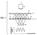
- the photoelectric encoder of grating interference type is of transmission type, light projected onto an index scale 12 from a light source 10 and diffracted on a grating 13 is again diffracted on a grating 15 on a main scale (simply, referred as scale) 14 to produce a light and dark interference fringe, this interference fringe is detected on a light reception element 20, and displacement of the scale 14 is detected, as shown in FIG. 1 .
- the photoelectric encoder of grating interference type is of reflection type
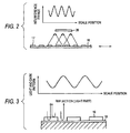
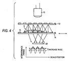
- an interference fringe is generated using light diffraction/interference through a phase grating 17 on a scale 16 as shown in FIG. 2 as with the transmission type shown in FIG. 1 or a portion where a phase grating 19 of a scale 18 does not exist is reflected and becomes a light part and a portion where the phase grating 19 exists becomes a dark part because of interference in such a manner that the phase difference between reflected light on the surface of the phase grating 19 and that on the bottom of the phase grating 19 becomes light wavelength/2 (a value obtained by dividing the light wavelength by 2), as shown in FIG. 3 .
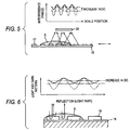
- the transmission type and the reflection type have a problem of a decrease in the signal strength if dirt exists on the scale surface. That is, in the transmission type in FIGs. 1 and 2 , if the light path length changes due to refraction because of dirt S on the scale surface and the direct current (DC) component of an interference fringe arriving at the light reception element 20 increases, worsening the contrast of the interference fringe, as in FIGs. 4 and 5 . On the other hand, in the reflection type in FIG. 3 , a phase difference changes due to dirt S, no interference occurs, and the direct current (DC) component increases, worsening the contrast of the interference fringe, as in FIG. 6 .
- US2003/0005595 discloses a sliding mechanism of an encoder and provides a protective film for protecting its diffraction grating from abrasion and corrosion.
- US517250 discloses a hologram scale having a base substrate, a hologram film with a diffraction grating of a desired pitch exposed thereon, adhered to the base substrate, and with a protective substrate to protect the hologram film.
- Adhesives having moisture resistance are applied between the base and the protective substrates to essentially surround the hologram film positioned on the base substrate.
- the protective and the base substrates are sealed integrally by the adhesives, securing the hologram film therein so as to protect it from ambient environmental conditions.
- a photoelectric encoder including a scale and an image forming optical system which move relatively to each other, adapted to detect relative displacement of the scale, wherein a transparent protective material having a thickness equal to or greater than a depth of focus of the image forming optical system is disposed on a surface of the scale where a grating is provided.
- the transparent protective material can be transparent tape bonded to the surface of the scale where the grating is provided or a transparent protective material applied to the surface of the scale where the grating is provided.
- the surface of the transparent protective material can have hydrophilicity or lipophilicity by using an oxide such as a titanium oxide, a titanium dioxide or the like. More specifically, the surface of the transparent protective material may be covered by a titanium oxide film or the transparent protective material may be made of a titanium oxide, so that the transparent protective material can have hydrophilicity. The surface of the transparent protective material may be covered by a titanium dioxide film or the transparent protective material may be made of a titanium dioxide, so that the transparent protective material can have lipophilicity. In an environment in which water is used, the transparent protective material has hydrophilicity, so that it is possible to prevent the water droplet from forming on the transparent protective material or the water from being accumulated on the transparent protective material because the water spreads on the transparent protective material.
- the transparent protective material has lipophilicity, so that it is possible to prevent the oil droplet from forming on the transparent protective material or the oil from being accumulated on the transparent protective material because the oil spreads on the transparent protective material. Therefore, it is possible to prevent the optical influence by the water droplet or oil droplet from occurring.
- the transparent protective material can have the characteristic of a filter.
- the image forming optical system can include an aperture.
- the transparent protective material has the thickness equal to or greater than the depth of focus (DOF) of the image forming optical system and thus the effect on image formation is small. Therefore, reliability for scale dirt is improved, the signal strength is stabilized, and the signal detection efficiency is improved. Moreover, the dirt portion spreads on he transparent protective material by means of the transparent protective material having hydrophilicity or lipophilicity, for example, the refractive power caused by the scale dirt lessens, and the interference fringe scarcely changes. Therefore, reliability for scale dirt is further improved, the signal strength is further stabilized, and the signal detection efficiency is further improved.
- DOF depth of focus
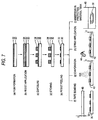
- a scale 14 having a grating 15 is formed by (a) forming a film 32 which becomes a grating on a base 30 made of glass or metal, for example, (b) applying a resist 34 onto the film, (c) exposing to light and removing a part of the resist 34, (d) etching and removing a part of the film 32, and (e) peeling off the resist 34, as shown in FIG. 7 .
- a transparent protective material is disposed by bonding transparent tape 40 made of glass or resin (PET film, etc.,) to the grating 15 side surface of the scale 14 by adhesiveness of the tape or with an adhesive as shown in (f), evaporating a transparent protective material 42 onto the grating side surface as shown in (g), applying a transparent protective material 42 to the grating side surface with a spray 44 as shown in (h), or immersing the whole in a protective material tank 46 as shown in (i).
- transparent tape 40 made of glass or resin (PET film, etc.
- a thickness t of each of the transparent protective materials 40 and 42 is equal to or greater than the depth of focus (DOF) of an image forming optical system.
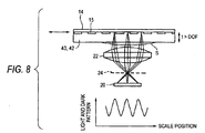
- FIG. 8 shows a first embodiment of the invention applied to a transmission encoder like that in FIG. 1 having an image forming optical system made of a lens 22.
- a transparent protective material 40 or 42 is disposed on a grating 15 side surface of a scale 14, whereby dirt S is deposited on the transparent protective material 40 or 42 rather than on the grating 15 face of the scale 14 and the dirt portion spreads because of hydrophilicity or lipophilicity. Therefore, the refractive power lessens and an interference fringe scarcely changes.
- the thickness t of the transparent protective material 40 or 42 is larger than the DOF and thus the effect on image formation through the lens 22 is small.
- the DOF lessens, so that the thickness t of the transparent protective material 40 or 42 can be thinned.
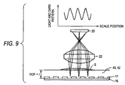
- FIG. 9 shows a second embodiment of the invention applied to a reflection encoder as shown in FIG. 2 .
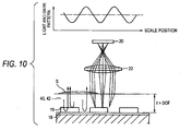
- FIG. 10 shows a third embodiment of the invention applied to a reflection encoder as shown in FIG. 3 .
- the portion of dirt S spreads and thus an interference fringe scarcely changes.
- thickness t of a transparent protective material 40 or 42 is larger than the DOF and thus the effect on image formation through a lens 22 is small.
- the transparent protective material can be implemented as a band-pass filter formed by multilayer coating by evaporation, for example, and can be provided with a function of removing external visible light, etc., for example, when an infrared light source is used.
- the aperture 24 may be added to the focal position of the lens 22, and in this case, since DOF lessens, the thickness t of the transparent protective material 40 or 42 can be thinned.
Landscapes
- Physics & Mathematics (AREA)
- General Physics & Mathematics (AREA)
- Optical Transform (AREA)
Claims (10)
- Photoelektrischer Codierer, der eine Skala (14) und ein optisches Bilderzeugungssystem (20, 22) aufweist, die sich relativ zueinander bewegen, ausgebildet zum Erfassen einer relativen Verschiebung der Skala (14),
wobei ein transparentes Schutzmaterial (40, 42) auf einer Oberfläche der Skala (14) angeordnet ist, wo ein Gitter (15) vorgesehen ist,
und dadurch gekennzeichnet, dass das transparente Schutzmaterial eine Dicke hat, die gleich oder größer ist als eine Tiefe eines Fokus des optischen Bilderzeugungssystems. - Der photoelektrische Codierer gemäß Anspruch 1, wobei das transparente Schutzmaterial (40, 42) ein transparentes Band ist, das auf die Oberfläche der Skala (14) geklebt ist, wo das Gitter (15) vorgesehen ist.
- Der photoelektrische Codierer gemäß Anspruch 1, wobei das transparente Schutzmaterial (40, 42) ein transparentes Schutzmaterial (40, 42) ist, das auf die Oberfläche der Skala (14) angewendet ist, wo das Gitter (15) vorgesehen ist.
- Der photoelektrische Codierer gemäß einem der Ansprüche 1 bis 3, wobei eine Oberfläche des transparenten Schutzmaterials (40, 42) hydrophil ist.
- Der photoelektrische Codierer gemäß einem der Ansprüche 1 bis 3, wobei eine Oberfläche des transparenten Schutzmaterials (40, 42) lipophil ist.
- Der photoelektrische Codierer gemäß einem der Ansprüche 1 bis 5, wobei das transparente Schutzmaterial (40, 42) die Eigenschaft eines Filters hat.
- Der photoelektrische Codierer gemäß einem der Ansprüche 1 bis 6, wobei das optische Bilderzeugungssystem (20, 22) eine Öffnung (24) umfasst.
- Der photoelektrische Codierer gemäß Anspruch 4, wobei das transparente Schutzmaterial (40, 42) aus Titandioxid besteht.
- Der photoelektrische Codierer gemäß Anspruch 5, wobei das transparente Schutzmaterial (40, 42) aus Titandioxid besteht.
- Der photoelektrische Codierer gemäß Anspruch 6, wobei das transparente Schutzmaterial (40, 42) ein Bandpassfilter ist, der durch Mehrschichtbeschichtung durch Verdampfen gebildet wird.
Applications Claiming Priority (1)
| Application Number | Priority Date | Filing Date | Title |
|---|---|---|---|
| JP2007140557A JP2008292406A (ja) | 2007-05-28 | 2007-05-28 | 光電式エンコーダ |
Publications (3)
| Publication Number | Publication Date |
|---|---|
| EP2000782A2 EP2000782A2 (de) | 2008-12-10 |
| EP2000782A3 EP2000782A3 (de) | 2011-10-05 |
| EP2000782B1 true EP2000782B1 (de) | 2016-02-17 |
Family
ID=39876644
Family Applications (1)
| Application Number | Title | Priority Date | Filing Date |
|---|---|---|---|
| EP08156987.3A Active EP2000782B1 (de) | 2007-05-28 | 2008-05-27 | Fotoelektrischer Kodierer |
Country Status (4)
| Country | Link |
|---|---|
| US (1) | US7642505B2 (de) |
| EP (1) | EP2000782B1 (de) |
| JP (1) | JP2008292406A (de) |
| CN (1) | CN101315290B (de) |
Families Citing this family (7)
| Publication number | Priority date | Publication date | Assignee | Title |
|---|---|---|---|---|
| NL2003638A (en) | 2008-12-03 | 2010-06-07 | Asml Netherlands Bv | Lithographic apparatus and device manufacturing method. |
| JP2011021909A (ja) * | 2009-07-13 | 2011-02-03 | Nikon Corp | エンコーダ用スケール、及びエンコーダ装置 |
| JP5893857B2 (ja) * | 2011-06-24 | 2016-03-23 | 株式会社ミツトヨ | スケールの目盛保護構造 |
| US9726560B2 (en) | 2011-10-31 | 2017-08-08 | Nsk Ltd. | Optical sensor, method for manufacturing optical sensor, optical encoder, torque detection apparatus, and electric power steering apparatus |
| JP6169392B2 (ja) * | 2013-03-29 | 2017-07-26 | 株式会社ミツトヨ | 光電式エンコーダ |
| JP6383460B1 (ja) * | 2017-05-31 | 2018-08-29 | 浜松ホトニクス株式会社 | エンコーダ用受光モジュール及びエンコーダ |
| JP7252809B2 (ja) * | 2019-03-28 | 2023-04-05 | 株式会社ミツトヨ | 光電式エンコーダおよび光電式エンコーダにおける演算方法 |
Family Cites Families (12)
| Publication number | Priority date | Publication date | Assignee | Title |
|---|---|---|---|---|
| JPH0615977B2 (ja) | 1988-12-21 | 1994-03-02 | 株式会社ミツトヨ | 格子干渉型変位計 |
| JP2557967B2 (ja) | 1988-12-21 | 1996-11-27 | 株式会社 ミツトヨ | 格子干渉型変位計 |
| JPH02176420A (ja) | 1988-12-27 | 1990-07-09 | Mitsutoyo Corp | 格子干渉型変位計及びそのスケール |
| DE69016058T2 (de) * | 1989-02-28 | 1995-09-07 | Sony Magnescale Inc | Feuchtigkeitsbeständige holographische Messskala. |
| DE4338680C1 (de) * | 1993-11-12 | 1995-03-23 | Heidenhain Gmbh Dr Johannes | Längen- oder Winkelmeßeinrichtung |
| DE19738751A1 (de) * | 1996-09-10 | 1998-03-12 | Harmonic Drive Systems | Optischer Codierer |
| JPH11118677A (ja) * | 1997-10-14 | 1999-04-30 | Hitachi Ltd | 校正用被検査物およびその製造方法ならびに検査装置の校正方法および検査装置 |
| JP4869505B2 (ja) * | 2001-06-27 | 2012-02-08 | 株式会社ミツトヨ | エンコーダの摺動機構 |
| JP2004198179A (ja) * | 2002-12-17 | 2004-07-15 | Yaskawa Electric Corp | 光学式エンコーダ |
| JP4398744B2 (ja) * | 2003-02-12 | 2010-01-13 | 株式会社ミツトヨ | 光電式エンコーダ |
| EP1447648B1 (de) * | 2003-02-12 | 2015-07-01 | Mitutoyo Corporation | Optischer Kodierer |
| JP2005315610A (ja) * | 2004-04-27 | 2005-11-10 | Matsushita Electric Ind Co Ltd | エンコーダ装置 |
-
2007
- 2007-05-28 JP JP2007140557A patent/JP2008292406A/ja active Pending
-
2008
- 2008-05-27 EP EP08156987.3A patent/EP2000782B1/de active Active
- 2008-05-28 US US12/128,201 patent/US7642505B2/en active Active
- 2008-05-28 CN CN2008101093510A patent/CN101315290B/zh not_active Expired - Fee Related
Also Published As
| Publication number | Publication date |
|---|---|
| US7642505B2 (en) | 2010-01-05 |
| US20080302953A1 (en) | 2008-12-11 |
| CN101315290A (zh) | 2008-12-03 |
| EP2000782A3 (de) | 2011-10-05 |
| CN101315290B (zh) | 2011-12-21 |
| EP2000782A2 (de) | 2008-12-10 |
| JP2008292406A (ja) | 2008-12-04 |
Similar Documents
| Publication | Publication Date | Title |
|---|---|---|
| EP2000782B1 (de) | Fotoelektrischer Kodierer | |
| US7430076B2 (en) | Diffraction element | |
| JP4971047B2 (ja) | 表面反射型エンコーダ用スケール及びそれを用いた表面反射型エンコーダ | |
| EP1557701A1 (de) | Photoelektrischer Positionsgeber und Verfahren zur Herstellung von Gittern | |
| JP2012532356A (ja) | 2つの有視範囲へ同時に集束するための光学モジュール | |
| US20210063318A1 (en) | Detection device for detecting contamination | |
| US20130112860A1 (en) | Reflective optical scale for encoder and reflective optical encoder | |
| US20060140538A1 (en) | Surface reflection type phase grating | |
| US5696584A (en) | Phase grating having an unprotected relief structure with a grating structure that causes destructive interference of reflections | |
| JPH05232318A (ja) | 反射形ホログラムスケール | |
| KR20000048253A (ko) | 타이밍 룰러 또는 타이밍 디스크 및 그 제조 방법 | |
| JP5443452B2 (ja) | 光学スケール、および、これを備える光学ユニット | |
| EP3926372B1 (de) | Optische komponente | |
| CN112147729A (zh) | 光栅部件及其制造方法 | |
| JP5789409B2 (ja) | 光学スケール | |
| US7343693B2 (en) | Scale assembly for optical encoder having affixed optical reference markers | |
| JP7167455B2 (ja) | エンコーダー用光学式スケールおよび光学式エンコーダー | |
| JP5052391B2 (ja) | 光学式エンコーダ | |
| JP2005114717A (ja) | 光学式エンコーダ | |
| JP7537649B1 (ja) | エンコーダ用反射型光学式スケール、反射型光学式エンコーダおよびエンコーダ用反射型光学式スケール用積層体 | |
| JP2010002324A (ja) | 光学式エンコーダ | |
| US20260009661A1 (en) | Measuring standard and optical position measuring device with this measuring standard | |
| US6633428B2 (en) | Optical module | |
| JP7139233B2 (ja) | 反射型スケール | |
| JP7330830B2 (ja) | 光電式エンコーダ |
Legal Events
| Date | Code | Title | Description |
|---|---|---|---|
| PUAI | Public reference made under article 153(3) epc to a published international application that has entered the european phase |
Free format text: ORIGINAL CODE: 0009012 |
|
| AK | Designated contracting states |
Kind code of ref document: A2 Designated state(s): AT BE BG CH CY CZ DE DK EE ES FI FR GB GR HR HU IE IS IT LI LT LU LV MC MT NL NO PL PT RO SE SI SK TR |
|
| AX | Request for extension of the european patent |
Extension state: AL BA MK RS |
|
| RIN1 | Information on inventor provided before grant (corrected) |
Inventor name: MIZUTANI, MIYAKO |
|
| PUAL | Search report despatched |
Free format text: ORIGINAL CODE: 0009013 |
|
| AK | Designated contracting states |
Kind code of ref document: A3 Designated state(s): AT BE BG CH CY CZ DE DK EE ES FI FR GB GR HR HU IE IS IT LI LT LU LV MC MT NL NO PL PT RO SE SI SK TR |
|
| AX | Request for extension of the european patent |
Extension state: AL BA MK RS |
|
| RIC1 | Information provided on ipc code assigned before grant |
Ipc: G01D 5/347 20060101AFI20110831BHEP |
|
| 17P | Request for examination filed |
Effective date: 20120403 |
|
| AKX | Designation fees paid |
Designated state(s): DE FR GB |
|
| GRAP | Despatch of communication of intention to grant a patent |
Free format text: ORIGINAL CODE: EPIDOSNIGR1 |
|
| INTG | Intention to grant announced |
Effective date: 20151009 |
|
| GRAS | Grant fee paid |
Free format text: ORIGINAL CODE: EPIDOSNIGR3 |
|
| GRAA | (expected) grant |
Free format text: ORIGINAL CODE: 0009210 |
|
| AK | Designated contracting states |
Kind code of ref document: B1 Designated state(s): DE FR GB |
|
| REG | Reference to a national code |
Ref country code: GB Ref legal event code: FG4D |
|
| REG | Reference to a national code |
Ref country code: DE Ref legal event code: R096 Ref document number: 602008042360 Country of ref document: DE |
|
| REG | Reference to a national code |
Ref country code: FR Ref legal event code: PLFP Year of fee payment: 9 |
|
| REG | Reference to a national code |
Ref country code: DE Ref legal event code: R097 Ref document number: 602008042360 Country of ref document: DE |
|
| PLBE | No opposition filed within time limit |
Free format text: ORIGINAL CODE: 0009261 |
|
| STAA | Information on the status of an ep patent application or granted ep patent |
Free format text: STATUS: NO OPPOSITION FILED WITHIN TIME LIMIT |
|
| 26N | No opposition filed |
Effective date: 20161118 |
|
| REG | Reference to a national code |
Ref country code: FR Ref legal event code: PLFP Year of fee payment: 10 |
|
| REG | Reference to a national code |
Ref country code: FR Ref legal event code: PLFP Year of fee payment: 11 |
|
| PGFP | Annual fee paid to national office [announced via postgrant information from national office to epo] |
Ref country code: FR Payment date: 20200522 Year of fee payment: 13 |
|
| PGFP | Annual fee paid to national office [announced via postgrant information from national office to epo] |
Ref country code: GB Payment date: 20200527 Year of fee payment: 13 |
|
| GBPC | Gb: european patent ceased through non-payment of renewal fee |
Effective date: 20210527 |
|
| PG25 | Lapsed in a contracting state [announced via postgrant information from national office to epo] |
Ref country code: GB Free format text: LAPSE BECAUSE OF NON-PAYMENT OF DUE FEES Effective date: 20210527 |
|
| PG25 | Lapsed in a contracting state [announced via postgrant information from national office to epo] |
Ref country code: FR Free format text: LAPSE BECAUSE OF NON-PAYMENT OF DUE FEES Effective date: 20210531 |
|
| PGFP | Annual fee paid to national office [announced via postgrant information from national office to epo] |
Ref country code: DE Payment date: 20250521 Year of fee payment: 18 |