EP2000708B1 - Steuervorrichtung für Fahrzeug und Parkmechanismus - Google Patents
Steuervorrichtung für Fahrzeug und Parkmechanismus Download PDFInfo
- Publication number
- EP2000708B1 EP2000708B1 EP08251949.7A EP08251949A EP2000708B1 EP 2000708 B1 EP2000708 B1 EP 2000708B1 EP 08251949 A EP08251949 A EP 08251949A EP 2000708 B1 EP2000708 B1 EP 2000708B1
- Authority
- EP
- European Patent Office
- Prior art keywords
- parking
- state
- lock
- operable
- control apparatus
- Prior art date
- Legal status (The legal status is an assumption and is not a legal conclusion. Google has not performed a legal analysis and makes no representation as to the accuracy of the status listed.)
- Ceased
Links
- 230000007246 mechanism Effects 0.000 title claims description 87
- 230000005540 biological transmission Effects 0.000 claims description 43
- 230000004044 response Effects 0.000 claims description 11
- 238000001514 detection method Methods 0.000 description 4
- 230000004043 responsiveness Effects 0.000 description 4
- 230000007935 neutral effect Effects 0.000 description 3
- 238000010586 diagram Methods 0.000 description 2
- 230000006870 function Effects 0.000 description 2
- 238000003860 storage Methods 0.000 description 2
- 230000007175 bidirectional communication Effects 0.000 description 1
- 230000008878 coupling Effects 0.000 description 1
- 238000010168 coupling process Methods 0.000 description 1
- 238000005859 coupling reaction Methods 0.000 description 1
- 238000005520 cutting process Methods 0.000 description 1
- 238000009434 installation Methods 0.000 description 1
- 238000004519 manufacturing process Methods 0.000 description 1
- 238000000034 method Methods 0.000 description 1
- 230000004048 modification Effects 0.000 description 1
- 238000012986 modification Methods 0.000 description 1
- 238000003825 pressing Methods 0.000 description 1
- 230000000717 retained effect Effects 0.000 description 1
- 239000010454 slate Substances 0.000 description 1
Images


Classifications
-
- F—MECHANICAL ENGINEERING; LIGHTING; HEATING; WEAPONS; BLASTING
- F16—ENGINEERING ELEMENTS AND UNITS; GENERAL MEASURES FOR PRODUCING AND MAINTAINING EFFECTIVE FUNCTIONING OF MACHINES OR INSTALLATIONS; THERMAL INSULATION IN GENERAL
- F16H—GEARING
- F16H63/00—Control outputs from the control unit to change-speed- or reversing-gearings for conveying rotary motion or to other devices than the final output mechanism
- F16H63/02—Final output mechanisms therefor; Actuating means for the final output mechanisms
- F16H63/30—Constructional features of the final output mechanisms
- F16H63/34—Locking or disabling mechanisms
- F16H63/3416—Parking lock mechanisms or brakes in the transmission
- F16H63/3458—Parking lock mechanisms or brakes in the transmission with electric actuating means, e.g. shift by wire
-
- F—MECHANICAL ENGINEERING; LIGHTING; HEATING; WEAPONS; BLASTING
- F16—ENGINEERING ELEMENTS AND UNITS; GENERAL MEASURES FOR PRODUCING AND MAINTAINING EFFECTIVE FUNCTIONING OF MACHINES OR INSTALLATIONS; THERMAL INSULATION IN GENERAL
- F16H—GEARING
- F16H63/00—Control outputs from the control unit to change-speed- or reversing-gearings for conveying rotary motion or to other devices than the final output mechanism
- F16H63/02—Final output mechanisms therefor; Actuating means for the final output mechanisms
- F16H63/30—Constructional features of the final output mechanisms
- F16H63/34—Locking or disabling mechanisms
- F16H63/3416—Parking lock mechanisms or brakes in the transmission
-
- F—MECHANICAL ENGINEERING; LIGHTING; HEATING; WEAPONS; BLASTING
- F16—ENGINEERING ELEMENTS AND UNITS; GENERAL MEASURES FOR PRODUCING AND MAINTAINING EFFECTIVE FUNCTIONING OF MACHINES OR INSTALLATIONS; THERMAL INSULATION IN GENERAL
- F16H—GEARING
- F16H63/00—Control outputs from the control unit to change-speed- or reversing-gearings for conveying rotary motion or to other devices than the final output mechanism
- F16H63/40—Control outputs from the control unit to change-speed- or reversing-gearings for conveying rotary motion or to other devices than the final output mechanism comprising signals other than signals for actuating the final output mechanisms
- F16H63/48—Signals to a parking brake or parking lock; Control of parking locks or brakes being part of the transmission
- F16H63/483—Circuits for controlling engagement of parking locks or brakes
-
- Y—GENERAL TAGGING OF NEW TECHNOLOGICAL DEVELOPMENTS; GENERAL TAGGING OF CROSS-SECTIONAL TECHNOLOGIES SPANNING OVER SEVERAL SECTIONS OF THE IPC; TECHNICAL SUBJECTS COVERED BY FORMER USPC CROSS-REFERENCE ART COLLECTIONS [XRACs] AND DIGESTS
- Y10—TECHNICAL SUBJECTS COVERED BY FORMER USPC
- Y10T—TECHNICAL SUBJECTS COVERED BY FORMER US CLASSIFICATION
- Y10T74/00—Machine element or mechanism
- Y10T74/19—Gearing
- Y10T74/19637—Gearing with brake means for gearing
Definitions
- the invention relates to a control apparatus for use in a vehicle, which has a shift-by-wire type parking mechanism for switching an output shaft of an automatic transmission mounted in, for example, a vehicle such as an automobile, between a lock state where the output shaft cannot rotate and an unlock state where the output shaft can rotate.
- the invention also relates to a shift-by-wire type parking mechanism for switching the output shaft of the automatic transmission between the lock state where the output shaft cannot rotate and the unlock state where the output shaft can rotate.
- An automatic transmission is generally designed to allow a driver to slide and operate the slide-type shift lever provided in the driver's seat so as to select, for example, the parking range P, the reverse (reverse travel) range R, the neutral range N, and the drive (forward travel) range D by transmitting the operating force of operating the shift lever directly to the parking mechanism or manual valve through a wire, a rod, or the like.
- the parking mechanism brings an output shaft of the automatic transmission into a lock state where the output shaft cannot rotate.
- the state of a manual valve which is one of the components of a shift range switching hydraulic circuit provided in the automatic transmission, is changed to engage or disengage friction engagement elements, such as the clutch and brake of a shifting mechanism portion, whereby the requested range is obtained.
- the parking mechanism is generally configured by a parking gear, a parking lock pawl, and a parking rod.
- the parking gear is fixed externally to the output shaft of the automatic transmission.
- the parking lock pawl is tiltably supported so as to be displaceable close to or away from the parking gear, and has a pawl capable of being engaged into or disengaged from the teeth of the parking gear.
- the parking rod is provided with a tapered cone at one end side for tilting the parking lock pawl, and is designed to be displaced forward or backward substantially parallel to the output shaft of the automatic transmission.
- This parking rod is driven by a detent lever that drives a manual valve.
- the detent lever is tilted by any appropriate actuator.
- the patterns of driving the detent lever include a pattern called direct operation system in which the detent lever is directly connected to a shift lever through, for example, the wire or rod and so as to move together and driven directly by the operating force of the shift lever, and a pattern which is so-called shift-by-wire system.
- a sensor, a switch or the like detects a driver's operation of the shift lever, and then the detent lever is driven by any appropriate actuator in response to a shift range signal obtained from the detection (see, for example, Japanese Patent Application Publication No. 5-280637 ( JP-A-5-280637 ), Japanese Patent Application Publication No. 2005-69407 ( JP-A-2005-69407 )).
- a joystick, a push button or the like besides the commonly-used shift lever described above is sometimes used as an operating member for outputting a parking request signal or a parking release request signal of the parking mechanism.
- the parking rod When operating the parking mechanism, first the parking rod is displaced backward, for example, by tilting the detent lever, and then the tapered cone pushes up the parking lock pawl so that the pawl of the parking lock pawl is engaged into the teeth of the parking gear, whereby the output shaft of the automatic transmission is brought into the lock state where the output shaft cannot rotate.
- the parking rod When, on the other hand, the parking rod is displaced forward, for example, by tilting the detent lever in a direction opposite to the above direction, the force of the tapered cone pushing up the parking lock pawl is released so that the parking lock pawl is pulled downward by a spring and the pawl is separated from the teeth of the parking gear, whereby the output shaft of the automatic transmission is brought into the unlock state where the output shaft can rotate.
- US 2007/0039798 discusses a parking brake apparatus for automatic transmission vehicle and method for controlling operation thereof.
- the invention has an object of reducing the time required for setting the lock state after receiving a request for a parking lock operation.
- the invention has an object of reducing the time required for setting the lock state after receiving the request for the parking lock operation.
- a first aspect of the invention is a control apparatus for use in a vehicle, which has a shift-by-wire type parking mechanism for switching an output shaft of an automatic transmission between a lock state where the output shaft cannot rotate and an unlock state where the output shaft can rotate, wherein the control apparatus controls an actuator of the parking mechanism to perform standby processing for bringing the parking mechanism from the unlock state into a standby state preceding the lock state to wait for a request for the parking lock operation when it is predicted that a parking lock operation is requested.
- the standby state may be a state in which the parking mechanism is positioned at a point immediately preceding the lock state.
- the control apparatus can bring the parking mechanism into the standby state preceding the lock slate when the control apparatus predicts that the parking lock operation is requested. Therefore, when the control apparatus receives the request for the parking lock operation in the course of bringing the parking mechanism into the standby state, the control apparatus can set the lock state immediately, whereby the time required for setting the lock state after the request is made can be reduced.
- the lock state can be set within a relatively short time, which contributes to improve responsiveness and reliability.
- the vehicle when performing the parking lock operation particularly on the sloping road, the vehicle can be prevented from moving in the course of bringing the parking mechanism into the lock state, so that the lock state can be set easily.
- the control apparatus may perform the abovementioned prediction by checking whether or not the vehicle speed is zero or less than a predetermined value close to zero.
- a condition for prediction may be specified so that the control apparatus can predict that the parking lock operation is requested when, for example, the vehicle speed is less than a certain speed.
- the control apparatus may perform the prediction of the request by, first, checking whether or not the vehicle is inclined and then, when the vehicle is inclined, checking whether or not a stopping condition is established, and may perform the abovementioned standby processing when the condition is established.
- the first aspect of the invention when it is predicted that the parking lock operation is requested while the vehicle is stopped on the sloping road, the first aspect of the invention can cope with such a request. Accordingly, the parking mechanism can be locked immediately even on the sloping road.
- a second aspect of the invention is a control apparatus for use in a vehicle, which has a shift-by-wire type parking mechanism for switching an output shaft of an automatic transmission between a lock state where the output shaft cannot rotate and an unlock state where the output shaft can rotate
- the control apparatus has: a posture detector that detects inclination of a stopped vehicle; a stop determination portion that determines whether or not a stopping condition is satisfied; a prediction portion that predicts that a parking lock operation is requested, when it is determined based on an output from the posture detector that the vehicle is inclined and it is determined based on an output from the stop determination portion that the stopping condition is satisfied; and a managing portion that brings the parking mechanism into the lock state or the unlock state in response to a parking request signal or a parking release request signal that is output from a manually operated operating member, and performing standby processing for bringing the parking mechanism from the unlock sate into a standby state preceding the lock state to wait for the parking request signal to be sent from the operating member when the prediction portion predicts that the
- This configuration can realize control during the parking lock operation and the standby processing.
- the stop determination may be performed by checking whether or not the vehicle speed is zero or less than a predetermined value close to zero.
- a pattern of performing the stop determination is specified so that the control apparatus can predict that the parking lock operation is requested when, for example, the vehicle speed is less than a certain speed.
- Tthe parking mechanism may be configured by a parking gear, a parking lock pawl, a parking rod, a detent lever, an actuator, and the operating member.
- the actuator is controlled to set the lock state when the parking request signal is received from the operating member and to bring the detent lever into a standby posture immediately preceding the lock state when the standby processing is executed.
- the parking gear is fixed externally to the output shaft of the automatic transmission.
- the parking lock pawl has a pawl that is latched to the parking gear, and is displaced so as to latch the pawl to the parking gear to bring the parking gear into the lock state where the output shaft cannot rotate or to separate the pawl from the parking gear to bring the parking gear into the unlock state where the output shaft can rotate.
- the parking rod is pushed and pulled so as to bring the parking lock pawl close to or away from the parking gear.
- the detent lever is tiltably supported so as to push and pull the parking rod.
- the actuator is for tilting the detent lever by a predetermined angle in an appropriate direction.
- the operating member is for outputting the parking request signal for setting the lock state in response to a manual operation.
- a configuration of the parking mechanism to be controlled is specified so that a configuration for performing the parking lock operation and a standby operation is defined.
- an example of the standby state of the parking mechanism that immediately precedes the lock state is a state in which the pawl of the paring lock pawl is brought, in a non-contact manner, to the parking gear as close as possible. Furthermore, a driving force that is generated by the actuator to bring the detent lever into the standby posture is called "pretorque.”
- the parking lock pawl can be brought into engagement with the parking gear immediately by slightly moving the pawl of the parking lock pawl toward the parking gear.
- the invention may has the following configuration in the shift-by-wire type parking mechanism for switching the output shaft of the automatic transmission between the lock state where the output shaft cannot rotate and the unlock state where the output shaft can rotate.
- the parking mechanism is configured by the parking gear, the parking lock pawl, the parking rod, the detent lever, the actuator, a latch lever, the operating member, and the control apparatus.
- the parking gear is fixed externally to the output shaft of the automatic transmission.
- the parking lock pawl has a pawl that is latched to the parking gear, and is displaced so as to latch the pawl to the parking gear to bring the parking gear into the lock state where the output shaft cannot rotate or to separate the pawl from the parking gear to bring the parking gear into the unlock state where the output shaft can rotate.
- the parking rod is pushed and pulled so as to bring the parking lock pawl close to or away from the parking gear.
- the detent lever is tiltably supported so as to push and pull the parking rod.
- the actuator is for tilting the detent lever by a predetermined angle in an appropriate direction.
- the latch lever is brought into engagement with a first engaging portion provided in the detent lever, to keep the detent lever in a tilted posture for performing the parking lock operation, and is also brought into engagement with a second engaging portion provided in the detent lever, to keep the detent lever in a tilted posture for releasing the parking lock.
- the operating member is for outputting the parking request signal for setting the lock state in response to a manual operation.
- the control apparatus drives the actuator in response to the parking request signal output from the operating member to perform processing for bringing the parking mechanism into the lock state, and drives the actuator to perform standby processing for bringing the parking mechanism from the unlock state into the standby state preceding the lock state to wait for the parking request signal to be sent from the operating member when it is predicted that the parking lock operation is requested.
- the standby state may be a state in which the parking mechanism is positioned at a point immediately preceding the lock state.
- the control apparatus can bring the parking mechanism into the standby state preceding the lock state when the control apparatus predicts that the parking lock operation is requested. Therefore, when the control apparatus receives the request for the parking lock operation in the course of bringing the parking mechanism into the standby state, the control apparatus can set the lock state immediately, whereby the time required for setting the lock state after the request is made can be reduced.
- the lock state can be set within a relatively short time, which contributes to improve responsiveness and reliability.
- the vehicle when performing the parking lock operation particularly on the sloping road, the vehicle can be prevented from moving in the course of bringing the parking mechanism into the lock state, so that the lock state can be set easily.
- the detent lever of the parking mechanism may be provided with a third engaging portion for keeping the detent lever in the standby posture in which the latch lever is engaged with the detent lever in order to keep the standby posture immediately preceding the lock state.
- the driving force (pretorque) generated by the actuator can be reduced during the standby period, which is advantageous in terms of alleviating the load on the actuator.
- the first to third engaging portions of the detent lever of the parking mechanism may be recess portions.
- the lock state can be set within a relatively short time after receiving the request for the parking lock operation, thereby improving responsiveness and reliability.
- FIGS. 1 to 9 show an embodiment of the invention. An outline of a power train of a vehicle to which the invention is applied is described with reference to FIG. 1 before explaining the characteristics of the invention.
- FIG. 1 shows a power train of front-engine front-drive (FF) type.
- the power train as shown in FIG. 1 has an engine 1 as a drive source, an automatic transmission 2, a drive wheel 3, a foot brake 4, a parking mechanism 5, an engine ECU 6 (Electronic Control Unit), an ECT (Electronic Controlled Automatic Transmission)_ECU 7, an ECB (Electronically Controlled Brake System)_ECU 8, and an SBW (Shift-by-Wirc)_ECU 9.
- This basic configuration is the same as a commonly known configuration, and thus the portions that are not directly related to the invention will he described briefly.
- the engine 1 is a gasoline-powered engine, a diesel engine or the like, and a driving operation thereof is controlled by the engine ECU 6.
- the automatic transmission 2 is mainly configured by a torque converter 21, a transmission mechanism portion 22, a hydraulic circuit 23 and the like, and a transmission operation of the automatic transmission 2 is controlled by the ECT_ECU 7.
- the transmission mechanism portion 22 of the automatic transmission 2 is configured mainly by a plurality of planetary gears, friction engagement elements such as a clutch and a brake, and one-way clutches, and is designed to set a required gear stage by engaging and/or releasing the friction engagement elements in accordance with an operation table predefined in the ECT-ECU 7.
- the hydraulic circuit 23 has at least a manual valve, and is designed to secure a hydraulic path for an appropriate friction engagement element in response to, for example, a reverse (reverse travel) range R, a neutral range N, or a drive (forward travel) range D.
- the drive wheel 3 is driven to rotate by transmission of a forward driving force or a reverse driving force via a differential 24 and an axle (reference numeral not shown) that are disposed within the automatic transmission 2.
- the brake 4 is in the form of, for example, a hydraulic disc brake and provides a frictional force to a disc rotor (reference numeral not shown) to apply a braking force to the drive wheel 3 when a driver performs pedaling operation on a brake pedal 41 installed within the vehicle.
- This brake 4 may be in the form of a drum brake.
- the pedaling force (stepping force) is amplified by a booster 42 and a master cylinder 43, and a strong braking force is obtained with a light stepping force.
- This brake 4 is provided with a brake hydraulic control unit 44 in the middle of a hydraulic path extending from the master cylinder 43 to a brake caliper (reference numeral not shown), in order to realize commonly known brake assist function and anti-lock brake function, and is designed to appropriately control the brake hydraulic control unit 44 by means of the brake ECU 8.
- the parking mechanism 5 is configured as shown in FIGS. 2 to 4 and configured in the form of a so-called shift-by-wire type parking mechanism, which, according to need, brings an output shaft 25 of the automatic transmission 2 into a lock state where the output shaft 25 cannot rotate or an unlock state where the output shaft 25 cannot rotate.
- the output shaft 25 of the automatic transmission 2 is in the form of, for example, a counter drive gear, but can be in the form of another power transmission shaft.
- the parking mechanism 5 is mainly configured by a parking switch 10, a parking gear 51, a parking lock pawl 52, a parking rod 53, a detent lever 54, a latch lever 55, a control shaft 56, and an actuator 57.
- the parking gear 51 is fixed externally to the output shaft 25 of the automatic transmission 2 so as to be able to rotate integrally therewith.
- the parking lock pawl 52 is disposed in the vicinity of the parking gear 51 so as to be tiltable with one end of the parking lock pawl 52 as a fulcrum.
- a pawl 52a capable of being engaged into or disengaged from the teeth of the parking gear 51 is provided in the middle of a longitudinal direction of the parking lock pawl 52.
- the parking rod 53 is disposed so as to be displaced toward a front end or a rear end of the parking rod 53 in substantially parallel to the output shaft 25 by a tilting operation of the detent lever 54.
- the front end of the parking rod 53 is coupled to the detent lever 54, and the rear end of the parking rod 53 is provided with a tapered cone 58 for tilting the parking lock pawl 52, as shown in FIG. 2 .
- the tapered cone 58 is pressed toward the parking gear 51 side by a coil spring 59.
- the coil spring 59 is attached externally on the parking rod 53, and one end of the coil spring 59 is supported by a snap ring (reference numeral not shown) that is latched and fixed to the parking rod 53.
- the detent lever 54 is configured such that a cylindrical boss portion 54a integrally formed on the detent lever 54 at the part causing the tilting is, for example, externally spline-fitted to a control shaft 56 so as to be able to rotate integrally with the control shaft 56.
- An upper end side of the detent lever 54 is provided with two engagement recess portions 54b, 54c.
- the parking rod 53 is coupled to the detent lever 54.
- a curved end of the parking rod 53 is inserted into a through-hole provided in a predetermined position of the detent lever 54, and then the detent lever 54 is retained fixed to this curved end by means of a snap ring or a latch pin, which is not shown.
- the latch lever 55 is for keeping the tilted posture of the detent lever 54, and configured such that a roller 55a, which is engaged with engagement recess portions 54b, 54c provided on the detent lever 54, is provided on one end of a main body that is composed of a leaf spring or the like the other end of which is fixed to an automatic transmission case (reference numeral not shown).
- the roller 55a of the latch lever 55 is engaged with the first engagement recess portion 54b when the parking mechanism is unlocked, i.e., when releasing the parking lock, and engaged with the second engagement recess portion 54c when the parking lock operation is performed.
- the control shaft 56 is supported rotatably by the automatic transmission case or the like, which is not shown, and reciprocally driven to rotate by a predetermined angle by the actuator 57.
- the actuator 57 is configured by an appropriate motor and a deceleration mechanism (e.g., a worm gear, a planetary gear, or the like). This actuator 57 is electrically controlled by the SBW_ECU 9 in response to a manual operation performed on, for example, the parking switch 10 serving as the operating member.
- a deceleration mechanism e.g., a worm gear, a planetary gear, or the like.
- the parking switch 10 is in the form of a toggle-type switch for allernately outputting a parking request signal and a parking release request signal every time, for example, a pressing operation is performed.
- Each of the ECUs 6, 7, 8 and 9 described above is configured by a CPU, a ROM, a RAM, a backup RAM and the like as is commonly known, and is capable of bi-dircctionally transmitting and receiving information required by all of these components.
- the ROM has stored therein various control programs and maps that are referred to when executing these various programs.
- the CPU executes various arithmetic processing based on the various control programs and maps stored in the ROM.
- the RAM is a memory for temporarily storing results of computation of the CPU and data that are input from each sensor
- the backup RAM is a nonvolatile memory for storing the data to be saved when, for example, stopping the engine 1.
- the parking request signal is output from the parking switch 10 and input to the SBW_ECU 9.
- the SBW_ECU 9 then controls the actuator 57 to rotate the control shaft 56 by a predetermined angle in a locking direction, e.g., a direction of positive rotation.
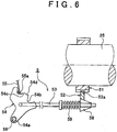
- control shaft 56 and the detent lever 54 are integrally tilted in the locking direction, whereby the parking rod 53 is pressed toward its rear end side. Then, a larger diameter side of the tapered cone 58 pushes up the parking lock pawl 52, whereby the pawl 52a is engaged into the teeth of the parking gear 51 (see FIGS. 6 and 8 ). Consequently, the parking mechanism 5 is brought into the lock state where the output shaft 25 cannot rotate. At this moment, because the roller 55a is engaged with the second engagement recess portion 54c of the detent lever 54, the posture of the detent lever 54 is defined and kept.
- the parking release request signal is output from the parking switch 10 and input to the SBW_ECU 9.
- the SBW_ECU 9 then controls the actuator 57 to rotate the control shaft 56 by a predetermined angle in an unlocking direction, e.g., a direction of negative rotation.
- the control shaft 56 and the detent lever 54 are integrally tilted in the unlocking direction. Consequently, the parking rod 53 and the tapered cone 58 are pulled toward the front end side, and the force of the tapered cone 58 pushing up the parking lock pawl 52 is released, whereby the parking lock pawl 52 descends and the pawl 52a separates from the teeth of the parking gear 51 (see FIGS. 3 and 4 ).
- the parking lock pawl 52 is always urged by a spring, not shown, in a direction of separating the parking lock pawl 52 from the parking gear 51.
- the parking mechanism 5 is brought into the unlock state where the output shaft 25 can rotate. At this moment, because the roller 55a of the latch lever 55 is engaged with the first engagement recess portion 54b of the detent lever 54, the posture of the detent lever 54 is defined and kept.
- This embodiment is basically contrived such that when it is predicted that the parking lock operation is requested, the actuator 57 of the parking mechanism 5 is controlled to perform the standby processing for bringing the parking mechanism 5 into a standby state immediately preceding the lock state to wait for the request for the parking lock operation.
- the detent lever 54 is brought into a standby posture immediately preceding the lock state by the actuator 57 (see FIG. 7 ).
- a driving force that is generated by the actuator 57 to bring the detent lever 54 into the standby posture is called "pretorque.”
- a third engagement recess portion 54d is provided at a mountain-shaped portion between the two engagement recess portions 54b, 54c of the detent lever 54.
- the third engagement recess portion 54d is so shaped that the roller 55a of the latch lever 55 can be engaged therewith, and is designed so as to be able to keep the detent lever 54 in the standby posture by bringing the roller 55a of the latch lever 55 into engagement with the third engagement recess portion 54d when the detent lever 54 is brought into the standby posture immediately preceding the lock state, as described above.
- the flowchart shown in FIG. 5 is the processing performed by the SBW_ECU 9, which is entered into every certain period.
- step S1 it is determined whether or not the request for the parking lock operation is received. This determination can be made by, for example, checking whether or not the parking request signal that is output from the parking switch 10 has been input by the driver operating the parking switch 10.
- step S1 when the parking request signal that is output from the parking switch 10 is input, the determination is made in the affirmative in step S1, and parking lock processing is executed in the subsequent steps S2 and S3, but when the parking request signal is not input, the determination is made in the negative in step S1 and the routine shifts to the flow from step S4 to S6.
- step S2 the parking lock processing is executed so as to bring the parking mechanism 5 into the lock state.
- the actuator 57 of the parking mechanism 5 is driven to bring the pawl 52a of the parking lock pawl 52 into engagement with the teeth of the parking gear 51.
- This step S2 is performed until it is determined in the subsequent step S3 that the parking lock is set.
- This determination can be made by, for example, checking whether or not the detent lever 54 is in the posture obtained when the parking range P is set, on the basis of detection signals from the sensors and the like, not shown.
- step S3 the determination is made in the negative in step S3, and step S2 is repeated until the parking lock processing is completed.
- the determination is made in the affirmative in step S3 and this flowchart is exited.
- step S4 to S6 the flow from step S4 to S6 will be described. Specifically, in steps S4 and S5 it is predicted whether or not the situation is such that the request for the parking lock operation is likely to be received, such as on a sloping road.
- step S4 it is determined whether or not the road surface on which the vehicle is about to stop or stopped is a sloping road. This determination can be made based on the output from a gradient sensor 12 installed in the vehicle.
- the gradient sensor 12 is posture detection means for detecting the posture of the vehicle.
- the vehicle When, for example, the vehicle is in a horizontal posture, it means that the road surface is flat.
- the vehicle When the vehicle is tilted upward, it means that the road surface is an upward slope.
- the vehicle When the vehicle is tilted downward, it means that the road surface is a downward slope.
- step S4 determines whether the road is a sloping road, i.e., in the case of a flat road.
- the determination is made in the negative in step S4 and the flowchart is exited.
- the determination is made in the affirmative in step S4 and the routine is shifted to step S5.
- step S5 It is determined in step S5 whether or not stopping conditions of the vehicle are established.
- the stopping conditions include a condition that the vehicle speed is zero or less than a predetermined speed close to zero (e.g., 0km/h to 3km/h);
- Detection of vehicle speed which is one of the stopping conditions, can be performed by reading the latest vehicle speed information saved in the temporary storage area of the ECT_ECU 7 through, for example, bidirectional communication with the ECT_ECU 7.
- the ECT_ECU 7 calculates the vehicle speed based on the output from, for example, a wheel speed sensor 11 and saves the result of calculation in the temporary storage area as the latest vehicle speed.
- step S5 when the stopping condition is not established, the determination is made in the negative in step S5, and the flowchart is exited.
- step S6 the determination is made in the affirmative in step S5 and the routine is shifted to step S6.
- step S6 the standby processing for bringing the parking mechanism 5 into the standby state immediately preceding the lock state is executed. Specifically, in step S6, the actuator 57 of the parking mechanism 5 is driven and thereby the pawl 52a of the parking lock pawl 52 is brought, in a non-contact manner, to the parking gear 51 to the position immediately preceding the engagement between the pawl 52a and the parking gear 51 (see FIGS. 7 and 9 ).
- the parking lock processing is executed in the steps S1 through S3, and engagement between the pawl 52a of the parking lock pawl 52 and the parking gear 51 can be made immediately by simply moving the pawl 52a slightly toward the parking gear 51, whereby the lock state can be set within a relatively short time.
- the SBW_ECU 9 may correspond to the control apparatus for a vehicle according to the invention.
- the engine ECU 6, the ECT_ECU 7, the brake ECU 8 and the SBW_ECU 9 are not provided separately but provided as a single overall control apparatus, such an overall control apparatus may correspond to the control apparatus for a vehicle according to the invention.
- the parking mechanism 5 when it is predicted that the request for the parking lock operation is likely to be received on the sloping road, the parking mechanism 5 is brought into the standby state immediately preceding the lock state. Therefore, when the request for the parking lock operation is received in the standby state, the lock state can be set immediately, and the time required for setting the lock state after receiving the request can be reduced.
- the vehicle can be prevented from moving in the course of bringing the parking mechanism 5 into the lock state, and the lock state can be set easily.
- the lock state of the parking mechanism 5 can be set within a relatively short time, contributing to improve responsiveness and reliability.
- the driving force (pretorque) generated by the actuator 57 can be reduced during the standby period. Therefore, for example, a small, low-power and inexpensive actuator can be adopted as the actuator 57 mounted in the parking mechanism 5, which is advantageous in terms of cutting installation cost.
- the determination of whether or not the brake 4 is actuated can be performed by, for example, causing the SBW_ECU 9 to communicate with the brake ECU 8 bi-directionally to check whether a brake actuation flag is "1" or "0.”
- the brake ECU 8 assumes that the brake 4 is actuated when an output value of a pressure sensor (not shown) annexed to the master cylinder 43 is equal to or higher than a predetermined value, and sets the brake actuation flag to "1," while assuming that the brake 4 is not actuated when the output value of the pressure sensor (not shown) of the master cylinder 43 is less than the predetermined value, and setting the brake actuation flag to "0.”
Landscapes
- Engineering & Computer Science (AREA)
- General Engineering & Computer Science (AREA)
- Mechanical Engineering (AREA)
- Gear-Shifting Mechanisms (AREA)
- Regulating Braking Force (AREA)
Claims (16)
- Ein Steuerungsgerät für ein Fahrzeug, das aufweist:einen Parkmechanismus (5) des Shift-by-wire-Typs, um eine Ausgabewelle eines Automatikgetriebes zwischen einem Verriegelungszustand, in dem die Ausgabewelle rotationsunfähig ist, und einem Entriegelungszustand, in dem die Ausgabewelle rotationsfähig ist, zu schalten,dadurch gekennzeichnet, dass das Steuerungsgerät aufweist:eine Steuereinrichtung (9), die betreibbar ist, um ein Stellglied (57) des Parkmechanismus zu steuern, um eine Bereitschaftsbearbeitung auszuführen, um den Parkmechanismus vom Entriegelungszustand in einen Bereitschaftszustand, der dem Verriegelungszustand vorangeht, hineinzubringen, um auf eine Anfrage zum Parkverriegelungsbetrieb zu warten, wenn es vorausgesagt wird, dass ein Parkverriegelungsbetrieb angefragt wird.
- Steuerungsgerät für ein Fahrzeug nach Anspruch 1, wobei die Steuereinrichtung (9) betreibbar ist, um zu bestimmen, ob eine Fahrzeuggeschwindigkeit null oder geringer als ein vorbestimmter Wert nahe an null ist oder nicht, und betreibbar ist, wenn die Fahrzeuggeschwindigkeit null oder geringer als ein vorbestimmter Wert nahe an null ist, um vorauszusagen, dass der Parkverriegelungsbetrieb angefragt wird.
- Steuerungsgerät für ein Fahrzeug nach Anspruch 1, wobei die Steuereinrichtung aufweist:einen Erfasser, der betreibbar ist, um zu erfassen, ob das Fahrzeug geneigt ist oder nicht, undeinen Stoppbestimmungsabschnitt, der betreibbar ist, um zu bestimmen, ob eine Stoppbedingung geschaffen ist oder nicht,wobei die Steuereinrichtung (9) betreibbar ist, um die Bereitschaftsbearbeitung auszuführen, wenn erfasst wird, dass das Fahrzeug geneigt ist und die Stoppbedingung geschaffen ist.
- Ein Steuerungsgerät für ein Fahrzeug nach Anspruch 1, das aufweist:einen Lageerfasser, der betreibbar ist, um eine Neigung eines gestoppten Fahrzeugs zu erfassen,einen Stoppbestimmungsabschnitt, der betreibbar ist, um zu bestimmen, ob eine Stoppbedingung erfüllt ist oder nicht, undeinen Voraussageabschnitt, der betreibbar ist, um vorauszusagen, dass ein Parkverriegelungsbetrieb angefragt wird, wenn basierend auf einer Ausgabe des Lageerfassers bestimmt wird, dass das Fahrzeug geneigt ist, und basierend auf einer Ausgabe des Stoppbestimmungsabschnitts bestimmt wird, dass die Stoppbedingung erfüllt ist, wobeidie Steuereinrichtung einen Verwaltungsabschnitt (9) aufweist, der betreibbar ist, um den Parkmechanismus als Antwort auf ein Parkanfragesignal oder ein Parkfreigabeanfragesignal, das von einem manuell betriebenen Betriebsglied ausgegeben wird, in den Verriegelungszustand oder den Entriegelungszustand hinein zu bringen.
- Steuerungsgerät für ein Fahrzeug nach Anspruch 3 oder 4, wobei der Stoppbestimmungsabschnitt betreibbar ist, wenn eine Fahrzeuggeschwindigkeit null oder geringer als ein vorbestimmter Wert nahe an null ist, um zu bestimmen, dass die Stoppbedingung geschaffen ist.
- Steuerungsgerät für ein Fahrzeug nach einem der Ansprüche 1 bis 5, wobei der Parkmechanismus enthält:ein Parkzahnrad (51), das an der Ausgabewelle des Automatikgetriebes extern befestigt ist,eine Parkverriegelungsklinke (52), die eine Klinke, die in dem Parkzahnrad eingeklinkt ist, hat, und verschoben ist, um die Klinke in das Parkzahnrad einzuklinken, um das Parkzahnrad in den Verriegelungszustand, in dem die Ausgabewelle rotationsunfähig ist, hineinzubringen oder um die Klinke vom Parkzahnrad zu separieren, um das Parkzahnrad in den Entriegelungszustand, in dem die Ausgabewelle rotationsfähig ist, hineinzubringen,ein Stellglied (57), das betreibbar ist, um die Parkverriegelungsklinke zu verschieben, unddas Betriebsglied (10), das betreibbar ist, um das Parkanfragesignal auszugeben, um den Verriegelungszustand als Antwort auf ein manuelles Betreiben einzustellen,wobei das Stellglied (57) gesteuert ist, um den Verriegelungszustand einzustellen, wenn das Parkanfragesignal von dem Betriebsglied (10) erhalten wird, und außerdem gesteuert ist, um die Klinke (52a) der Parkverriegelungsklinke (52) in eine Bereitschaftslage, die dem Verriegelungszustand unmittelbar vorangeht, hineinzubringen, wenn die Bereitschaftsbearbeitung ausgeführt wird.
- Steuerungsgerät für ein Fahrzeug nach Anspruch 6, wobei der Parkmechanismus außerdem eine Parkstange (53), die betreibbar ist, um geschoben und gezogen zu werden, um die Parkverriegelungsklinke (52) nahe an das Parkzahnrad (51) oder weg von diesem zu bringen, und einen Arretierungshebel (54), der kippbar gestützt ist, um die Parkstange zu schieben und zu ziehen, enthält,
und wobei das Stellglied (57) betreibbar ist, um die Parkverriegelungsklinke (52) durch ein Kippen des Arretierungshebels (54) um einen vorbestimmten Winkel in eine geeignete Richtung zu verschieben. - Steuerungsgerät für ein Fahrzeug nach einem der Ansprüche 1 bis 7, wobei der Bereitschaftszustand ein Zustand ist, in dem der Parkmechanismus an einem Punkt, der dem Verriegelungszustand unmittelbar vorangeht, positioniert ist.
- Steuerungsgerät für ein Fahrzeug nach einem der Ansprüche 1 bis 7, wobei der Bereitschaftszustand ein Zustand ist, in dem der Parkmechanismus näher zu dem Entriegelungszustand als zu dem Verriegelungszustand positioniert ist.
- Steuerungsgerät für ein Fahrzeug nach einem der Ansprüche 1 bis 7, wobei der Bereitschaftszustand ein Zustand ist, in dem der Parkmechanismus einfacher in den Verriegelungszustand als in den Entriegelungszustand geschaltet wird.
- Steuerungsgerät für ein Fahrzeug nach Anspruch 1, wobei der Parkmechanismus (5) aufweist:ein Parkzahnrad (51), der an der Ausgabewelle des Automatikgetriebes extern befestigt ist,eine Parkverriegelungsklinke (52), die eine Klinke (52a), die in das Parkzahnrad eingeklinkt ist, hat und betreibbar ist, um verschoben zu werden, um die Klinke in das Parkzahnrad einzuklinken, um das Parkzahnrad in einen Verriegelungszustand, in dem die Ausgabewelle rotationsunfähig ist, hineinzubringen oder um die Klinke vom Parkzahnrad zu separieren, um das Parkzahnrad in einen Entriegelungszustand, in dem die Ausgabewelle rotationsfähig ist, hineinzubringen,eine Parkstange (53), die betreibbar ist, um geschoben und gezogen zu werden, um die Parkverriegelungsklinke nahe an das Parkzahnrad oder weg von diesem zu bringen,einen Arretierungshebel (54), der kippbar gestützt ist, um die Parkstange zu schieben und zu ziehen,das Stellglied (57), das betreibbar ist, um den Arretierungshebel um einen vorbestimmten Winkel in eine angemessene Richtung zu kippen,einen Riegelhebel (55), der betreibbar ist, um in Eingriff mit einem ersten Eingriffsabschnitt, der in dem Arretierungshebel vorgesehen ist, gebracht zu werden, um den Arretierungshebel in einer gekippten Lage zu halten, um einen Parkverriegelungsbetrieb auszuführen, und der auch betreibbar ist, um in Eingriff mit einem zweiten Eingriffsabschnitt, der in dem Arretierungshebel vorgesehen ist, gebracht zu werden, um den Arretierungshebel in einer gekippten Lage zu halten, um eine Parkverriegelung freizugeben, undein Betriebsglied (10), das betreibbar ist, um ein Parkanfragesignal auszugeben, um den Verriegelungszustand als Antwort auf einen manuellen Betrieb einzustellen, wobei die Steuereinrichtung (9), die betreibbar ist, um das Stellglied (57) zu steuern, die Steuereinrichtung aufweist, die betreibbar ist, um das Stellglied (57) als Antwort zu dem Parkanfragesignal, das von dem Betriebsglied ausgegeben wird, anzutreiben, um die Bearbeitung auszuführen, um den Parkmechanismus in den Verriegelungszustand zu bringen, und betreibbar ist, um das Stellglied (57) anzutreiben, um die Bereitschaftsbearbeitung auszuführen, um den Parkmechanismus vom Verriegelungszustand in einen Bereitschaftszustand, der dem Verriegelungszustand vorangeht, zu bringen, um auf das Parkanfragesignal, das von dem Betriebsglied gesendet werden soll, zu warten, wenn vorausgesagt ist, dass der Parkverriegelungsbetrieb angefragt wird.
- Steuerungsgerät nach Anspruch 11, wobei der Bereitschaftszustand ein Zustand ist, in dem der Parkmechanismus an einem Punkt, der dem Verriegelungszustand unmittelbar vorangeht, positioniert ist.
- Steuerungsgerät nach Anspruch 11 oder 12, wobei der Arretierungshebel mit einem dritten Eingriffsabschnitt (54d) versehen ist, um den Arretierungshebel in einer Bereitschaftslage zu halten, in der der Riegelhebel mit dem Arretierungshebel in Eingriff steht, um die Bereitschaftslage, die dem Verriegelungszustand unmittelbar vorangeht, zu halten.
- Steuerungsgerät nach Anspruch 13, wobei die Eingriffsabschnitte des Arretierungshebels, erster bis dritter Eingriffsabschnitt (54b, 54c, 54d), Aussparungsabschnitte sind.
- Steuerungsgerät nach Anspruch 14, wobei der Aussparungsabschnitt, der dem dritten Eingriffsabschnitt (54d) entspricht, flacher als die Aussparungsabschnitte, die dem ersten Eingriffsabschnitt (54c) und dem zweiten Eingriffsabschnitt (54b) entsprechen, ist.
- Steuerungsgerät nach einem der Ansprüche 13 bis 15, wobei der dritte Eingriffsabschnitt (54d) zwischen dem ersten Eingriffsabschnitt (54c) und dem zweiten Eingriffsabschnitt (54b) vorgesehen ist.
Applications Claiming Priority (1)
| Application Number | Priority Date | Filing Date | Title |
|---|---|---|---|
| JP2007150648A JP4400652B2 (ja) | 2007-06-06 | 2007-06-06 | パーキング機構 |
Publications (3)
| Publication Number | Publication Date |
|---|---|
| EP2000708A2 EP2000708A2 (de) | 2008-12-10 |
| EP2000708A3 EP2000708A3 (de) | 2012-03-07 |
| EP2000708B1 true EP2000708B1 (de) | 2017-10-25 |
Family
ID=39708020
Family Applications (1)
| Application Number | Title | Priority Date | Filing Date |
|---|---|---|---|
| EP08251949.7A Ceased EP2000708B1 (de) | 2007-06-06 | 2008-06-05 | Steuervorrichtung für Fahrzeug und Parkmechanismus |
Country Status (3)
| Country | Link |
|---|---|
| US (1) | US7735619B2 (de) |
| EP (1) | EP2000708B1 (de) |
| JP (1) | JP4400652B2 (de) |
Families Citing this family (18)
| Publication number | Priority date | Publication date | Assignee | Title |
|---|---|---|---|---|
| JP5212729B2 (ja) * | 2009-03-26 | 2013-06-19 | アイシン精機株式会社 | パーキングロック装置 |
| US9239108B2 (en) * | 2009-11-27 | 2016-01-19 | Stoneridge Control Devices, Inc. | Shift-by-wire transmission range selector system and actuator for the same |
| DE102009054874A1 (de) * | 2009-12-17 | 2011-06-22 | ZF Friedrichshafen AG, 88046 | Parksperrenvorrichtung mit Notbetätigungsvorrichtung für ein Fahrzeuggetriebe |
| JP5251888B2 (ja) * | 2010-01-08 | 2013-07-31 | 株式会社デンソー | 坂道発進補助装置及びプログラム |
| JP5093859B2 (ja) * | 2010-03-03 | 2012-12-12 | 網矢 貞幸 | 低速自動車装置 |
| DE102010029401B4 (de) * | 2010-05-27 | 2013-08-29 | Gkn Driveline International Gmbh | Parksperrenanordnung mit Notentriegelung |
| US20120000743A1 (en) * | 2010-07-02 | 2012-01-05 | Gm Global Technology Operations, Inc. | Hill-holder assembly for a transmission |
| DE102010060549A1 (de) * | 2010-11-15 | 2012-05-16 | Tente Gmbh & Co. Kg | Rolle |
| JP2015059604A (ja) | 2013-09-18 | 2015-03-30 | アイシン精機株式会社 | 自動変速装置 |
| DE102013220396B4 (de) * | 2013-10-10 | 2021-05-06 | Bayerische Motoren Werke Aktiengesellschaft | Parksperre für Kraftfahrzeuge |
| JP6201839B2 (ja) * | 2014-03-18 | 2017-09-27 | アイシン・エィ・ダブリュ株式会社 | パーキング装置 |
| US9371909B2 (en) | 2014-07-25 | 2016-06-21 | GM Global Technology Operations LLC | Method of controlling a transmission park system of a vehicle equipped with an electronic transmission range select system |
| JP6493367B2 (ja) * | 2016-11-22 | 2019-04-03 | トヨタ自動車株式会社 | パーキングロック機構の手動解除装置 |
| DE102017214904B4 (de) * | 2017-08-25 | 2021-05-06 | Audi Ag | Verfahren zum Einlegen einer Parksperre eines Kraftfahrzeugs, sowie Kraftfahrzeug mit einer Parksperre |
| DE102019200600B3 (de) | 2018-10-15 | 2020-06-18 | Vitesco Technologies Germany Gmbh | Verfahren zur Prädiktion einer Störung an einem Aktuator in einem Fahrzeug und applikationsspezifischer Schaltkreis zur Umsetzung eines solchen Verfahrens |
| GB2592602A (en) * | 2020-03-03 | 2021-09-08 | Airbus Operations Ltd | An aircraft parking brake |
| US12160584B2 (en) * | 2022-01-04 | 2024-12-03 | Mediatek Inc. | Video encoding apparatus for performing video compression with aid of content activity analysis and associated video encoding method |
| CN117281693A (zh) * | 2022-06-20 | 2023-12-26 | 武汉联影智融医疗科技有限公司 | 辅助装置及输送设备 |
Family Cites Families (11)
| Publication number | Priority date | Publication date | Assignee | Title |
|---|---|---|---|---|
| JPS58207571A (ja) * | 1982-05-28 | 1983-12-03 | Aisin Warner Ltd | 自動変速機パ−キング機構 |
| JP2943505B2 (ja) | 1992-02-05 | 1999-08-30 | トヨタ自動車株式会社 | 自動変速機用制御機構の誤操作防止装置 |
| JP2943547B2 (ja) | 1992-12-21 | 1999-08-30 | トヨタ自動車株式会社 | シフトバイワイヤ自動変速機の制御装置 |
| JP3575357B2 (ja) * | 1999-11-25 | 2004-10-13 | 日産自動車株式会社 | 自動変速機のパークロック装置 |
| KR100729251B1 (ko) * | 2003-04-04 | 2007-06-15 | 도요다 지도샤 가부시끼가이샤 | 시프트 제어 시스템, 시프트 제어 방법 및 시프트 스위칭디바이스 |
| JP4487516B2 (ja) | 2003-08-26 | 2010-06-23 | トヨタ自動車株式会社 | 車両用パーキングロック装置 |
| JP2005069407A (ja) | 2003-08-26 | 2005-03-17 | Toyota Motor Corp | 動力伝達機構の制御装置 |
| JP4246084B2 (ja) | 2004-02-17 | 2009-04-02 | 日産自動車株式会社 | 車両用走行制御装置 |
| JP4576922B2 (ja) | 2004-08-06 | 2010-11-10 | 日産自動車株式会社 | 車両用走行制御装置 |
| JP2006256478A (ja) | 2005-03-17 | 2006-09-28 | Nissan Motor Co Ltd | 走行制御装置 |
| KR100657706B1 (ko) * | 2005-08-19 | 2006-12-14 | 현대자동차주식회사 | 자동 변속기 차량의 파킹 브레이크 장치 및 그 제어방법 |
-
2007
- 2007-06-06 JP JP2007150648A patent/JP4400652B2/ja not_active Expired - Fee Related
-
2008
- 2008-06-05 EP EP08251949.7A patent/EP2000708B1/de not_active Ceased
- 2008-06-06 US US12/134,387 patent/US7735619B2/en not_active Expired - Fee Related
Non-Patent Citations (1)
| Title |
|---|
| None * |
Also Published As
| Publication number | Publication date |
|---|---|
| EP2000708A3 (de) | 2012-03-07 |
| EP2000708A2 (de) | 2008-12-10 |
| US7735619B2 (en) | 2010-06-15 |
| JP2008302768A (ja) | 2008-12-18 |
| US20080302627A1 (en) | 2008-12-11 |
| JP4400652B2 (ja) | 2010-01-20 |
Similar Documents
| Publication | Publication Date | Title |
|---|---|---|
| EP2000708B1 (de) | Steuervorrichtung für Fahrzeug und Parkmechanismus | |
| JP4179388B1 (ja) | 車両用制御装置 | |
| CN110778710B (zh) | 用于辅助换出驻车挡的车辆驻车系统及方法 | |
| JP5895907B2 (ja) | 車両用シフト制御装置 | |
| US20080051252A1 (en) | Apparatus for facilitating release of the parking lock | |
| JP5087358B2 (ja) | 作業車両のペダルロック制御装置 | |
| US7963882B2 (en) | Range-switching device of automatic transmission, and control method of the device | |
| KR101575414B1 (ko) | 차량의 변속 장치 | |
| JP2008307996A (ja) | 車両用制御装置 | |
| JP5018235B2 (ja) | 車両用制御装置 | |
| JPH08282456A (ja) | 坂道発進補助装置 | |
| JP5251888B2 (ja) | 坂道発進補助装置及びプログラム | |
| US7152725B2 (en) | Control system for transmission | |
| CN100546853C (zh) | 车辆减速控制装置 | |
| JP4586493B2 (ja) | 自動変速機の制御装置 | |
| JP5087359B2 (ja) | 作業車両のペダルロック制御装置 | |
| CN118722630A (zh) | 车辆控制装置与方法 | |
| US7563193B2 (en) | Method for actuating the transmission of a motor vehicle having a hybrid drive mechanism and actuation device for applying the method | |
| US12320422B1 (en) | Control device for vehicle | |
| JP4836855B2 (ja) | 自動変速機のシフト機構 | |
| JP2010228702A (ja) | 車両用手動運転装置 | |
| JP2019026086A (ja) | 車両のヒルホールド制御装置 | |
| JPH0820321A (ja) | 坂道発進補助装置 |
Legal Events
| Date | Code | Title | Description |
|---|---|---|---|
| PUAI | Public reference made under article 153(3) epc to a published international application that has entered the european phase |
Free format text: ORIGINAL CODE: 0009012 |
|
| 17P | Request for examination filed |
Effective date: 20080630 |
|
| AK | Designated contracting states |
Kind code of ref document: A2 Designated state(s): AT BE BG CH CY CZ DE DK EE ES FI FR GB GR HR HU IE IS IT LI LT LU LV MC MT NL NO PL PT RO SE SI SK TR |
|
| AX | Request for extension of the european patent |
Extension state: AL BA MK RS |
|
| PUAL | Search report despatched |
Free format text: ORIGINAL CODE: 0009013 |
|
| AK | Designated contracting states |
Kind code of ref document: A3 Designated state(s): AT BE BG CH CY CZ DE DK EE ES FI FR GB GR HR HU IE IS IT LI LT LU LV MC MT NL NO PL PT RO SE SI SK TR |
|
| AX | Request for extension of the european patent |
Extension state: AL BA MK RS |
|
| RIC1 | Information provided on ipc code assigned before grant |
Ipc: F16H 63/48 20060101AFI20120130BHEP |
|
| AKX | Designation fees paid |
Designated state(s): DE FR |
|
| RAP1 | Party data changed (applicant data changed or rights of an application transferred) |
Owner name: TOYOTA JIDOSHA KABUSHIKI KAISHA |
|
| GRAP | Despatch of communication of intention to grant a patent |
Free format text: ORIGINAL CODE: EPIDOSNIGR1 |
|
| STAA | Information on the status of an ep patent application or granted ep patent |
Free format text: STATUS: GRANT OF PATENT IS INTENDED |
|
| INTG | Intention to grant announced |
Effective date: 20170518 |
|
| RIN1 | Information on inventor provided before grant (corrected) |
Inventor name: KAWAMOTO, ATSUSHI Inventor name: KATO, SHINGO Inventor name: IMAEDA, FUMIMORI |
|
| GRAS | Grant fee paid |
Free format text: ORIGINAL CODE: EPIDOSNIGR3 |
|
| GRAA | (expected) grant |
Free format text: ORIGINAL CODE: 0009210 |
|
| STAA | Information on the status of an ep patent application or granted ep patent |
Free format text: STATUS: THE PATENT HAS BEEN GRANTED |
|
| AK | Designated contracting states |
Kind code of ref document: B1 Designated state(s): DE FR |
|
| REG | Reference to a national code |
Ref country code: DE Ref legal event code: R096 Ref document number: 602008052623 Country of ref document: DE |
|
| REG | Reference to a national code |
Ref country code: DE Ref legal event code: R084 Ref document number: 602008052623 Country of ref document: DE |
|
| REG | Reference to a national code |
Ref country code: FR Ref legal event code: PLFP Year of fee payment: 11 |
|
| REG | Reference to a national code |
Ref country code: DE Ref legal event code: R097 Ref document number: 602008052623 Country of ref document: DE |
|
| PLBE | No opposition filed within time limit |
Free format text: ORIGINAL CODE: 0009261 |
|
| STAA | Information on the status of an ep patent application or granted ep patent |
Free format text: STATUS: NO OPPOSITION FILED WITHIN TIME LIMIT |
|
| 26N | No opposition filed |
Effective date: 20180726 |
|
| PGFP | Annual fee paid to national office [announced via postgrant information from national office to epo] |
Ref country code: DE Payment date: 20190521 Year of fee payment: 12 |
|
| PGFP | Annual fee paid to national office [announced via postgrant information from national office to epo] |
Ref country code: FR Payment date: 20190510 Year of fee payment: 12 |
|
| REG | Reference to a national code |
Ref country code: DE Ref legal event code: R119 Ref document number: 602008052623 Country of ref document: DE |
|
| PG25 | Lapsed in a contracting state [announced via postgrant information from national office to epo] |
Ref country code: FR Free format text: LAPSE BECAUSE OF NON-PAYMENT OF DUE FEES Effective date: 20200630 |
|
| PG25 | Lapsed in a contracting state [announced via postgrant information from national office to epo] |
Ref country code: DE Free format text: LAPSE BECAUSE OF NON-PAYMENT OF DUE FEES Effective date: 20210101 |