EP2000706B1 - Système pour prévenir les dommages sur un véhicule - Google Patents
Système pour prévenir les dommages sur un véhicule Download PDFInfo
- Publication number
- EP2000706B1 EP2000706B1 EP08156946A EP08156946A EP2000706B1 EP 2000706 B1 EP2000706 B1 EP 2000706B1 EP 08156946 A EP08156946 A EP 08156946A EP 08156946 A EP08156946 A EP 08156946A EP 2000706 B1 EP2000706 B1 EP 2000706B1
- Authority
- EP
- European Patent Office
- Prior art keywords
- oil
- vehicle
- processor
- transmission
- operable
- Prior art date
- Legal status (The legal status is an assumption and is not a legal conclusion. Google has not performed a legal analysis and makes no representation as to the accuracy of the status listed.)
- Expired - Fee Related
Links
Images
Classifications
-
- F—MECHANICAL ENGINEERING; LIGHTING; HEATING; WEAPONS; BLASTING
- F16—ENGINEERING ELEMENTS AND UNITS; GENERAL MEASURES FOR PRODUCING AND MAINTAINING EFFECTIVE FUNCTIONING OF MACHINES OR INSTALLATIONS; THERMAL INSULATION IN GENERAL
- F16H—GEARING
- F16H57/00—General details of gearing
- F16H57/04—Features relating to lubrication or cooling or heating
- F16H57/0412—Cooling or heating; Control of temperature
- F16H57/0413—Controlled cooling or heating of lubricant; Temperature control therefor
-
- B—PERFORMING OPERATIONS; TRANSPORTING
- B60—VEHICLES IN GENERAL
- B60R—VEHICLES, VEHICLE FITTINGS, OR VEHICLE PARTS, NOT OTHERWISE PROVIDED FOR
- B60R16/00—Electric or fluid circuits specially adapted for vehicles and not otherwise provided for; Arrangement of elements of electric or fluid circuits specially adapted for vehicles and not otherwise provided for
- B60R16/02—Electric or fluid circuits specially adapted for vehicles and not otherwise provided for; Arrangement of elements of electric or fluid circuits specially adapted for vehicles and not otherwise provided for electric constitutive elements
- B60R16/023—Electric or fluid circuits specially adapted for vehicles and not otherwise provided for; Arrangement of elements of electric or fluid circuits specially adapted for vehicles and not otherwise provided for electric constitutive elements for transmission of signals between vehicle parts or subsystems
- B60R16/0231—Circuits relating to the driving or the functioning of the vehicle
- B60R16/0232—Circuits relating to the driving or the functioning of the vehicle for measuring vehicle parameters and indicating critical, abnormal or dangerous conditions
- B60R16/0234—Circuits relating to the driving or the functioning of the vehicle for measuring vehicle parameters and indicating critical, abnormal or dangerous conditions related to maintenance or repairing of vehicles
-
- F—MECHANICAL ENGINEERING; LIGHTING; HEATING; WEAPONS; BLASTING
- F16—ENGINEERING ELEMENTS AND UNITS; GENERAL MEASURES FOR PRODUCING AND MAINTAINING EFFECTIVE FUNCTIONING OF MACHINES OR INSTALLATIONS; THERMAL INSULATION IN GENERAL
- F16H—GEARING
- F16H57/00—General details of gearing
- F16H57/01—Monitoring wear or stress of gearing elements, e.g. for triggering maintenance
-
- F—MECHANICAL ENGINEERING; LIGHTING; HEATING; WEAPONS; BLASTING
- F16—ENGINEERING ELEMENTS AND UNITS; GENERAL MEASURES FOR PRODUCING AND MAINTAINING EFFECTIVE FUNCTIONING OF MACHINES OR INSTALLATIONS; THERMAL INSULATION IN GENERAL
- F16H—GEARING
- F16H57/00—General details of gearing
- F16H2057/0081—Fixing of, or adapting to transmission failure
-
- F—MECHANICAL ENGINEERING; LIGHTING; HEATING; WEAPONS; BLASTING
- F16—ENGINEERING ELEMENTS AND UNITS; GENERAL MEASURES FOR PRODUCING AND MAINTAINING EFFECTIVE FUNCTIONING OF MACHINES OR INSTALLATIONS; THERMAL INSULATION IN GENERAL
- F16H—GEARING
- F16H57/00—General details of gearing
- F16H57/04—Features relating to lubrication or cooling or heating
- F16H57/0447—Control of lubricant levels, e.g. lubricant level control dependent on temperature
- F16H57/0449—Sensors or indicators for controlling the fluid level
Definitions
- This invention relates to vehicle systems, specifically to such systems used for preventing damage to a vehicle.
- Vehicles such as cars and trucks, are used on a daily basis for transporting people and commercial cargo as well as providing private and public services.
- Engines, transmissions, and other vehicle components operate under a wide range of mechanical stress, pressure, and climates. As time passes, the vehicle components experience degradation, such as oil wear, mechanical fractures, increased transmission and non-transmission assembly component temperatures, and/or oil leakage.
- One method for monitoring temperature in a vehicle is to use a sensor to measure, for example, oil-sump temperature and to warn the driver of potentially dangerous temperatures via an indicator.
- transmission oil volume can be monitored using sight-gauges and/or dipsticks.
- these methods provide the driver with limited information (e.g ., a simple indicator light) and/or require the driver to stop and inspect the vehicle to prevent damage or further damage to the vehicle. In some cases, significant vehicle damage has already occurred before a driver can stop the vehicle. Accordingly, there is a need for improved methods and systems to prevent damage to a vehicle.
- EP 0 863 490 A2 discloses a s ystem according to the preamble of claim 1.
- the invention provides a system for preventing damage to a vehicle according to claim 1.
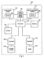
- Figure 1 is a block diagram illustrating an exemplary embodiment of system for preventing damage to a vehicle.
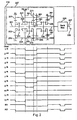
- Figure 2 is a schematic and a torque flow diagram illustrating an exemplary embodiment of a transmission system used in the system of Figure 1 .
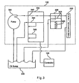
- FIG 3 is a schematic diagram illustrating an exemplary embodiment of a cooling circuit used in the system of Figure 1 .
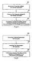
- Figure 4 is a flowchart illustrating an example of a method for preventing damage to a vehicle.
- Figure 5 is a flowchart illustrating another example of a method for preventing damage to a vehicle.
- FIG. 1 is a block diagram illustrating an exemplary embodiment of a system for preventing damage to a vehicle 100.
- the vehicle 100 may be a car, bus, truck, or any other known or future vehicle that utilizes an automatic, automated mechanical, or manual transmission.
- the system for preventing damage may include, but is not limited to, a transmission system 110, a non-transmission system 114, a starter interlock signal device 154, a processor 120, a memory 122, a display 124, a flow port controller 128, a cooling circuit 130, a baffle controller 140, and a baffle 144.
- the transmission system 110 may include, but is not limited to, a transmission, such as an automatic, automated mechanical, or manual transmission, and a sensor 150.
- the sensor 150 may be one sensor or a plurality of sensors capable of monitoring or measuring a parameter of a transmission component.
- the sensor 150 may be a mechanical, electrical, and/or optical sensor that is on or in a vehicle transmission operable to measure angular velocity of a shaft, temperature of transmission oil, level of the transmission oil, and/or volumetric flow rate of the transmission oil.
- the sensor 150 may be outside of the transmission system 110.
- the non-transmission system 114 may include, but is not limited to, a non-transmission assembly and sensor 160.
- the non-transmission assembly may be, for example, an exhaust system, engine, axle, clutch, differential, or brake of the vehicle 100.
- the sensor 160 may be one sensor or a plurality of sensors capable of monitoring or measuring a parameter of a non-transmission assembly component.
- the sensor 160 may be a mechanical, electrical, and/or optical sensor that is on or in the exhaust system of the vehicle 100 operable to measure temperature of the exhaust or the exhaust pipe.
- the sensor 160 may be positioned on or in any part of the vehicle 100 and may be operable to measure temperature, velocity, flow rate, and volume of any non-transmission assembly component, such as non-transmission oil, of the vehicle 100.
- the starter interlock signal device 154 may be in communication with the transmission system 110, the non-transmission system 114, and/or the processor 120.
- the starter interlock signal device 154 may be a mechanical and/or electrical switch in the transmission system 110, the non-transmission system 114, or any other section of the vehicle 100.
- the starter interlock signal device may be a neutral switch in the transmission system 110.
- the starter interlock signal device 154 may be in communication with a transmission controller, and the transmission controller may be in communication with or connected with a vehicle wiring harness.
- the starter interlock signal device 154 may be directly in communication with the vehicle wiring harness.
- the starter interlock signal device 154 may provide a starter interlock signal to drive an engine start enable relay.
- the starter interlock signal may be a low active signal that is asserted before an engine is allowed to start.
- the display 124 may be any mechanical and/or electronic display positioned for accessible viewing by a driver or passenger of the vehicle 100.
- the display 124 may be a light emitting diode, ("LED”), display or liquid crystal display, ("LCD”), in or on a dashboard of the vehicle 100.
- the display 124 may be capable of showing or illuminating various measurements, such as measurements by the sensor 150 or the sensor 160, calculations or derivations by the processor 120, and/or warnings.
- the cooling circuit 130 is operable to cool or transfer heat away from transmission oil of the vehicle 100.
- the cooling circuit 130 may also be used for cooling other various liquids or oils that are used in the operation of the vehicle 100.
- the flow port controller 128 may be a single mechanical and/or electrical controller or a plurality of such controllers operable to control the operation of the cooling circuit 130.
- the flow port controller 128 may include, but is not limited to, a solenoid.
- Various parts of the cooling circuit 130 may be controlled by other mechanical and/or electronic components of the vehicle 100.
- all or parts of the cooling circuit 130 as well as the flow port controller 128 may be incorporated in the transmission system 110, the non-transmission system 114, and/or any other section of the vehicle 100.
- the baffle 144 may be operable to direct or redirect air flow to any component of the vehicle 100, such as components of the transmission system 110 and/or the non-transmission system 114.
- the baffle may be any plate, wall, screen, or other known or future device operable to deflect air or regulate air flow.
- the baffle 144 may be a plurality of such devices.
- the baffle may be positioned in any part of the vehicle 100 (e.g., the front of the vehicle 100) and may be electronically controlled by the baffle controller 140.
- the baffle controller 140 may be a single mechanical and/or electrical controller or a plurality of such controllers.
- the processor 120 may be in communication with the memory 122, the sensor 150, the sensor 160, the starter interlock signal device 154, the display 124, the flow port controller 128, and the baffle controller 140.
- the processor 120 may be in communication with any other component of the transmission system 110 and/or the non-transmission system 114, such as a transmission controller, other vehicle controllers, or various electronics in the vehicle 100.
- the memory 122 may also be in communication with the sensors 150 and 160, the vehicle controllers, and the various electronics in the vehicle 100.
- the processor 120 and the memory 122 may be in the transmission system 110, the non-transmission system 114, and/or any other section of the vehicle 100.
- the processor 120 may be a main processor or a plurality of processors operable to communicate with electronics and controllers of the vehicle 100.
- the processor 120 may be part of a public or private communications area network ("CAN").
- the processor 120 may utilize a public electronic communication protocol, such as SAE J 1939 or SAE J 1587, and/or may utilize a proprietary electronic communication protocol or any other type of public or private communication technique.
- the system for preventing damage may perform a variety of processes or actions to prevent damage to the vehicle 100.
- Damage to the vehicle 100 may include, but is not limited to, bluing or blackening of gears when the temperature in the transmission system 110 and/or the non-transmission system 114 rises to a high level, breaking or fracturing of the gears because of high temperatures, oil breakdown, and bearing seizures. Blued or blackened gears may signify that the gear is approaching a physical break or fracture.
- Other damage may include transmission and/or non-transmission system 114 breakdown when there is a low level oil or no oil, other vehicle component malfunctions, and/or generation of smoke and fire.
- the sensor 160 may continuously or periodically measure a non-transmission assembly component in a non-transmission assembly.
- the sensor 160 may measure temperature of an exhaust pipe or exhaust and/or non-transmission oil and send the temperature data to the processor 120.
- the processor may communicate with the baffle controller 140 to adjust the baffle 144 to redirect or route air over the some part of or the entire exhaust system and/or some part of or the entire non-transmission assembly associated with the non-transmission oil to facilitate convective cooling.
- the sensor 150 may continuously or periodically monitor a transmission component.
- the sensor 150 may monitor temperature of the transmission oil and send the temperature data to the processor 120.
- the processor may communicate with the baffle controller 140 to adjust the baffle 144 to redirect or route air over the transmission to facilitate convective cooling.
- the baffle 144 may be adjusted to redirect or route air to any component of the vehicle 100 to facilitate convective cooling.
- EGR exhaust gas re-circulation
- the processor 120 may analyze the temperature data and prohibit or discontinue EGR when the temperature of a transmission component, such as transmission oil, and/or the temperature of a non-transmission assembly component, such as an exhaust pipe or exhaust, reaches or rises above a predetermined threshold. The decision to prohibit or discontinue EGR may occur when the vehicle 100 is moving or at a standstill.
- the sensor 150 may continuously or periodically measure temperature the transmission oil and send the temperature data to the processor 120.
- the processor 120 may analyze the data and send commands to the starter interlock signal device 154 to disable the starter interlock signal when the temperature is too high.
- the sensor 150 may directly communicate with the starter interlock signal device 154.
- the sensor 150 may directly send a signal to any part of the vehicle 100 to shut down all or some power.
- the sensor 150 may directly send a signal to the vehicle wiring harness to prohibit ignition.
- ignition may be prohibited when there is not enough oil in the transmission and/or non-transmission system. Oil levels of the transmission may drop if there is leakage or may be low because of other reasons, for example, if not enough oil was deposited in the transmission.
- the sensor 150 may continuously or periodically measure the level of oil or volumetric flow rate of oil in the transmission. The processor 120 may analyze that data and determine if the oil level or volumetric flow rate is sufficient for operation of the vehicle 100. If the oil level or volumetric flow rate reaches or is below a predetermined threshold, the processor 120 may send commands to the starter interlock signal device 154 to disable the starter interlock signal. Alternatively, the sensor 150 may directly communicate with the starter interlock signal device 154. Or, the sensor 150 may directly send a signal to any part of the vehicle 100 to shut down all or some power. For example, the sensor 150 may directly send a signal to the vehicle wiring harness to prohibit ignition.
- the sensor 160 may continuously or periodically measure temperature of components in the non-transmission system 114 and send the temperature data to the processor 120.
- the processor 120 may analyze the data and send commands to the starter interlock signal device 154 to disable the starter interlock signal when the temperature is too high.
- the sensor 160 may directly communicate with the starter interlock signal device 154.
- the sensor 160 may directly send a signal to any part of the vehicle 100 to shut down all or some power.
- the sensor 160 may directly send a signal to the vehicle wiring harness to prohibit ignition.
- the processor 120 may be operable to calculate a time period before damage to the vehicle 100 occurs.
- the sensor 150 and/or 160 may continuously or periodically measure the level of oil or volumetric flow rate of oil in the transmission and/or in a non-transmission assembly, respectively.
- the processor 120 may analyze that data and compare it to empirical or stored data that correlates different volumes of oil to specific damage. Therefore, if there is a leak and the volume of oil is decreasing or if the volume of oil is at a constant low level, the processor 120 may calculate a time period before damage will occur to the vehicle 100 based on interpolation and/or extrapolation of the stored data. This time period may be displayed on the display 124 in a countdown fashion.
- the driver may be continuously or periodically warned via a series of flashing or constant lights and/or alarms by visual and/or audio indicators.
- the oil level may be displayed on the display 124 to warn the driver. If the time period is substantially short, such as about zero seconds or minutes, the processor 120 may initiate other damage prevention processes immediately.
- the sensors 150 and 160 may measure the temperature of the transmission system 110 and the non-transmission system 114, respectively, and the processor 120 may determine a time period before damage occurs based on temperature.
- the sensor 150 may continuously or periodically measure temperature of the transmission oil and send the temperature data to the processor 120.
- the processor 120 may analyze that data and compare it to empirical or stored data that correlates different temperatures to specific damage.
- the processor 120 may calculate a time period before damage will occur to the vehicle 100 based on interpolation and/or extrapolation of the stored data. This time period may be displayed on the display 124 in a countdown fashion.
- the driver may be continuously or periodically warned via a series of flashing or constant lights and/or alarms by visual and/or audio indicators. If the time period is substantially short, such as about zero seconds or minutes, the processor 120 may initiate other damage prevention processes immediately.
- the processor 120 may be operable to correlate transmission and/or non-transmission oil temperature and transmission and/or non-transmission oil level or volume.
- Empirical or stored data linking different oil levels or oil volumes with respective oil temperatures may be provided.
- equations including variables for pressure, volume, and temperature may be used to correlate transmission and/or non-transmission oil temperature and transmission and/or non-transmission oil level or volume.
- the sensor 154 and/or 160 may continuously or periodically measure the transmission and/or non-transmission oil temperature and send the temperature data to the processor 120.
- the processor 120 may analyze that data and calculate the oil level or volume based on interpolation or extrapolation of the stored data and/or calculation of an equation that relates volume and temperature of the oil.
- the processor 120 may send commands, if appropriate, to initiate damage prevention processes discussed above.
- the sensor 150 and/or 160 may monitor oil level or volumetric flow rate, and the processor 120 may calculate an oil temperature based on the measured data and act accordingly.
- Oil Damage may occur to the vehicle 100 due to transmission and/or non-transmission oil wear.
- Oil may be designed to lubricate gears and other components, but the lubrication quality may decline as the oil ages, which results in more heat generation. Also, as oil ages, residual metals and sludge may build up adding to the heat generation. Therefore, the processor 120 may be operable to calculate or determine oil life or oil wear of the transmission system 110 and/or non-transmission system 114. Empirical or stored data linking oil life or wear with oil temperatures may be provided. For example, the sensor 150 and/or 160 may continuously or periodically measure the oil temperature and send the temperature data to the processor 120.
- the processor 120 may analyze that data and calculate the oil life or wear based on interpolation or extrapolation of the stored data and/or calculation of various equations or mathematical computations.
- Empirical or stored data relating oil quality or life to specific damage to the vehicle 100 may be provided as well.
- the oil life may be displayed on the display 124 in a countdown fashion to warn the driver of when to change the oil and/or when damage to the vehicle 100 is likely to occur.
- the display 124 may show a date and time for a driver to act and/or may show a series of flashing or constant lights. A quality level of the oil wear may also be shown on the display 124.
- FIG 2 is a schematic and a torque flow diagram illustrating an exemplary embodiment of a transmission system, such as the transmission system 110 of Figure 1 .
- the transmission system 110 may include a twelve speed overdrive transmission with two reverse gear settings designated R1 and R2 and 12 forward gear settings designated 1 st , 2 nd , 3 rd , Vietnamese,12 th , which are typically referred to as R1 gear, R2 gear, 1 st gear, ....12 th gear, respectively.
- the transmission may include, but is not limited to, an input shaft 201, a main shaft 205, counter shafts 221 and 223, a back box 225, and an output shaft 207.
- the transmission may include gear arrangements designated as KI, KII or 3, 2, 1, and R.
- the gear arrangement Kl may include a gear 251 that may be fixed on the counter shaft 221, a gear 255 that may be fixed on the counter shaft 223, and a gear 253 that may be operable to rotate around the input shaft 201.
- the gear arrangement KII or 3 may include a gear 261 that may be fixed on the counter shaft 221, a gear 265 that may be fixed on the counter shaft 223, and a gear 263 that may be operable to rotate around the input shaft 201.
- a synchronizer 231 may engage the gear 253 to rotate it about the input shaft 201 and, therefore, rotate gears 251 and 255. Also, the synchronizer 231 may engage the gear 263 to rotate it about the input shaft 201 and, therefore, rotate gears 261 and 265.
- the gear arrangement 2 may include a gear 271 that may be fixed on the counter shaft 221, a gear 275 that may be fixed on the counter shaft 223, and a gear 273 that may be operable to rotate about the main shaft 205.
- a dog clutch 235 may engage the gear 263 allowing the main shaft 205 to rotate based on the gear arrangement KII or 3.
- the dog clutch 235 may engage the gear 273 allowing the main shaft 205 to rotate based on the gear arrangement 2.
- the gear arrangement 1 may include, a gear 281 that may be fixed on the counter shaft 221, a gear 285 that may be fixed on the counter shaft 223, and a gear 283 that may be operable to rotate about the main shaft 205.
- the gear arrangement R may include a gear 291 that may be fixed on the counter shaft 221, a gear 299 that may be fixed on the counter shaft 223, idler gears 293 and 297 that may be operable to reverse the direction of rotation, and a gear 295 that may be operable to rotate about the main shaft 205.
- a dog clutch 239 may engage the gear 283 allowing the main shaft 205 to rotate based on the gear arrangement 1.
- the dog clutch 239 may engage the gear 295 allowing the main shaft 205 to rotate based on the gear arrangement R.
- the back box 225 may be a planetary back box that may include, but is not limited to, a sun gear, planetary gears ( e.g., three planetary gears), and a synchronizer.
- the output shaft 207 may be operatively coupled to the back box 225.
- a yoke 209 may be attached to the output shaft 207, and the yoke 209 may connect with a drive line, drive shaft, or propeller shaft.
- the torque or power flow through the transmission may vary depending on what gear setting the transmission is in. For example, referring to Figure 2 , 1 st gear may occur when the synchronizer 231 is engaged with the gear 263 and the dog clutch 239 is engaged with the gear 283.
- the input shaft 201 may rotate the gear 263, which in turn rotates the counter shafts 221 and 223 via the gears 261 and 265, respectively.
- the gear 283 may rotate the main shaft 205 via the gears 281 and 285. Therefore, the torque or power may flow through the input shaft 201 to the counter shafts 221 and 223 via the gear arrangement Kil or 3 and down to the main shaft 205 via the gear arrangement 1, as shown by the power or torque pattern in Figure 2 .
- the system for preventing damage to the vehicle 100 may shift to a gear setting that minimizes the number of engaged gears, such as direct gear.
- the sensors 150 and 160 may continuously or periodically measure the temperature of transmission oil and/or the temperature of the exhaust pipe or exhaust, respectively. Other components may be monitored as well.
- the processor 120 may send commands to the transmission system 110 ( e.g ., via a transmission controller) to shift to a direct gear to reduce heat generation.
- 5 th and 11 th gear are direct gears in a front box 227.
- the synchronizer 231 and the dog clutch 235 may simultaneously engage gear 263 directly connecting the input shaft 201 and the main shaft 205. Therefore, the torque or power may flow directly through the input shaft 201 and the main shaft 205.
- the torque flow to the output shaft 207 may depend on the engagement of gears within the back box 225.
- the 11 th gear has direct torque or power flow from the input shaft 201 to the output shaft 207, thus 11 th gear may also be a direct gear in the back box 225.
- 5 th gear shows a jog in the torque or power flow based on a gear arrangement within the back box 225. Therefore, the processor 120 may command the transmission system 110 to shift to 11 th gear at higher speeds to reduce heat generation and shift to 5 th gear at lower speeds to reduce heat generation. Therefore, shifting to a direct gear reduces heat generated in the transmission.
- Any type of transmission with any number of drive speeds may be used with the system for preventing damage to the vehicle 100.
- Some or all of the gears of the transmission may continuously rotate even if they are not engaged. Also, the diameters of the gears may vary.
- the diameter or size of the gears may also affect the generation of heat in the transmission system 110.
- the counter shafts 221 and 223 as well as their associated gears may reach into an oil sump.
- the other shafts, such as the input shaft 201, the main shaft 205, and the output shaft 207, and their associated gears may also reach into the oil sump.
- they may displace or churn a certain amount of oil, which generates heat. Therefore, when a component temperature of the transmission system 110 and/or the non-transmission system 114 reaches or rises above a predetermined threshold, the system for preventing damage to the vehicle 100 may shift to a gear arrangement having gears with smaller diameters to displace less oil and reduce heat generation.
- the sensors 150 and 160 may continuously or periodically measure the temperature of oil and/or the temperature of the exhaust pipe or exhaust, respectively. Other components may be monitored as well.
- the processor 120 may send commands to the transmission system 110 ( e.g., via a transmission controller) to shift to a gear or gear arrangement that utilizes gears with smaller diameters to displace less oil in the oil sump. The displacement of less oil generates less heat. However, the use of smaller diameter gears may generate more torque. Therefore, the processor 120 may be operable to weigh and calculate the benefits of heat reduction based on displacement of oil versus torque generated.
- the processor may send a command to the transmission system 110 for choosing a gear set based on the calculated benefits.
- the processor may send a pattern of different commands to switch between gears sets, including a shift to a direct gear, based on the benefits of heat reduction at a given time.
- the system for preventing damage to the vehicle 100 may shift to or prohibit a shift to any gear of the transmission system 110 to reduce heat generation.
- empirical data may be developed to define which gear arrangements generate the least amount of heat. This data may be used in the system for preventing damage to the vehicle 100 to shift to gear arrangements having the least amount of heat generation.
- FIG 3 is a schematic diagram illustrating an exemplary embodiment of a cooling circuit, such as the cooling circuit 130 of Figure 1 .
- the cooling circuit 130 may include, but is not limited to, an oil pump 300, a variable flow bypass 304, a pressure bypass 308, and a heat exchanger 320.
- the cooling circuit 130 may be operable to cool or transfer heat away from the oil of the transmission and/or oil of non-transmission assemblies.
- the pump may take in oil from an oil sump 330.
- the pump 300 may output the oil to the variable flow bypass 304.
- the oil may flow through a path 340 of the variable flow bypass 304 to a pressure bypass 308.
- the pressure bypass 308 may be operable to protect the heat exchanger 320. For example, if the pressure of the oil is above a predetermined threshold or great enough to move a piston 323 that is supported by a spring 325, then the oil returns to the oil sump 330 without passing through the heat exchanger 320. This is to protect the heat exchanger 320 from excessive or high oil pressures that may physically damage the heat exchanger 320. If the pressure of the oil is below the predetermined threshold, then the oil passes through the heat exchanger 320, which cools the oil, and the oil returns to the oil sump 330.
- the variable flow bypass 304 may have three flow paths including, but not limited to, the path 340, a path 344, and a path 348.
- the flow path 340 may route the oil from the pump 300 to the pressure bypass 308.
- the path 344 may route a portion of the oil to the pressure bypass 308 and the other portion to the oil sump 330.
- the path 348 may route all of the oil back to the oil sump 330, bypassing both the pressure bypass 308 and the heat exchanger 320.
- the variable flow bypass 304 may be utilized for preventing damage to the vehicle 100.
- the sensor 150 may continuously or periodically measure the level of oil or volumetric flow rate of oil in the transmission.
- the processor 120 may analyze that data and determine if the oil level or volumetric flow rate is sufficient for operation of the vehicle 100. If the oil level or volumetric flow rate reaches or is below a predetermined threshold (e.g., there is an oil leak or not enough oil was deposited in the transmission), the processor 120 may send commands to the flow port controller 128 to select a flow path. The processor 120 may determine that the oil level or volume is too low and command the flow port controller 128 to select the path 348.
- a predetermined threshold e.g., there is an oil leak or not enough oil was deposited in the transmission
- all of the oil may bypass the pressure bypass 308 and the heat exchanger 320 to keep as much oil as possible in the transmission.
- the processor 120 may command the controller 128 to select the path 344.
- a selected portion of the oil may bypass the pressure bypass 308 and the heat exchanger 320 to keep some oil in the transmission system 110 and the other portion of oil may be sent to the heat exchanger 320 for cooling.
- the path 344 may be designed with two constant flow paths for the respective portions of oil or may have varying flow paths allowing for a precise selection of oil to be diverted to the heat exchanger 320 or oil sump 330.
- the cooling circuit 130 may prevent damage to the vehicle 100 by increasing oil flow rate to the heat exchanger 320.
- the sensor 150 and/or 160 may continuously or periodically measure temperature of the transmission oil and/or non-transmission oil and send the temperature data to the processor 120.
- the processor 120 may analyze the data and send commands to the pump 300 to increase the flow of oil when the oil temperature is too high or above a predetermined threshold.
- the processor 120 may send commands to the flow port controller 128 to increase the diameter of the paths of the variable flow bypass 304 that direct the oil to the heat exchanger 320.
- the oil may become highly viscous.
- the thick oil may cause performance problems as well as damage to the vehicle. Therefore, the sensor 150 and/or 160 may monitor or measure the oil viscosity and/or temperature and send that data to the processor 120.
- the processor 120 may analyze the data to determine if the oil temperature is too low or below a predetermined threshold and/or if the oil is too viscous, thick, or above a predetermined threshold. If the oil is too cold or viscous, the processor 120 may command the flow port controller 128 to select the path 344 or 348 to keep all or some of the oil from entering the heat exchanger 320 to heat the oil faster and avoid any damage to the vehicle 100.
- the flow port controller 128 is not limited to controlling the variable flow bypass 304.
- the flow port controller 128 may be operable to control and/or communicate with any other part of the cooling circuit 130.
- FIG. 4 is a flowchart illustrating an example of a method for preventing damage to the vehicle 100.
- a parameter of a vehicle component may be measured or monitored.
- the vehicle component may be a transmission and/or non-transmission assembly.
- the transmission component may be oil of the transmission, and the non-transmission assembly component may be, for example, an exhaust pipe or exhaust.
- the parameter may be angular velocity of a shaft or gear, temperature of the transmission component or non-transmission assembly component, or volume, level, or volumetric flow rate of a component, such as transmission and/or non-transmission oil.
- Sensors that may be located at various positions in the vehicle 100, such as the sensors 150 and 160, may monitor or measure such parameters.
- the parameter of the vehicle component may be analyzed.
- a processor or a plurality of processors may analyze the measured data. The analysis may include, but is not limited to, determining if a parameter is above or below a predetermined threshold, interpolating and/or extrapolating stored data, comparing measured data with stored data, calculating a time period before damage occurs to a vehicle, such as vehicle 100, correlating oil temperature and oil volume or level, and determining oil life or wear based on the temperature of the oil.
- a damage prevention process including reducing heat generation in the vehicle based on the analysis of the parameter may be performed.
- Reducing heat generation may include, but is not limited to, shifting to a direct gear, shifting to a gear that displaces or churns less oil, prohibiting or discontinuing EGR, redirecting or routing air to a non-transmission assembly or a transmission, and increasing flow rate in a cooler circuit.
- Other damage prevention processes may include warning a driver of oil life or wear, level of oil, and a time period before damage will occur to the vehicle, as well as, prohibiting ignition based on oil level or temperature of a transmission and/or non-transmission assembly component, and bypassing oil or a selected portion of oil away from a heat exchanger based on oil level or temperature.
- Figure 5 is a flowchart illustrating another example of a method for preventing damage to a vehicle.
- a parameter of oil of a vehicle transmission and/or a non-transmission assembly may be monitored or measured.
- the parameter may be oil temperature, level, volume, volumetric flow rate, or viscosity.
- the parameter of the oil of the vehicle transmission may be analyzed. The analysis includes, but is not limited to, determining a time period before damage to the vehicle based on the oil level or the volumetric flow rate of the oil, correlating oil temperature and the oil level of the volumetric flow rate of the oil, and other analyses discussed above.
- a damage prevention process may be performed based on the analysis of the oil.
- the damage prevention process may include, but is not limited to, warning a driver about the time period before damage to the vehicle, bypassing the oil or a selected amount of the oil away from a heat exchanger when the oil level or the volumetric flow rate of the oil is below a predetermined threshold, prohibiting ignition when the oil level is too low or if the oil temperature is too high, and any other damage preventing process related to transmission oil discussed above.
- the memory 122 may include instructions for performing the steps of any of the methods, processes, calculations, or features described above.
- the memory 122 may be a "computer-readable medium,” “machine-readable medium,” “propagated-signal” medium, and/or “signal-bearing medium” and may comprise any device that contains, stores, communicates, propagates, or transports software for use by or in connection with an instruction executable system, apparatus, or device.
- the machine-readable medium may selectively be, but not limited to, an electronic, magnetic, optical, electromagnetic, infrared, or semiconductor system, apparatus, device, or propagation medium.
- a non-exhaustive list of examples of a machine-readable medium would include: an electrical connection "electronic”' having one or more wires, a portable magnetic or optical disk, a volatile memory such as a Random Access Memory “RAM” (electronic), a Read-Only Memory “ROM” (electronic), an Erasable Programmable Read-Only Memory (EPROM or Flash memory) (electronic), or an optical fiber (optical).
- a machine-readable medium may also include a tangible medium upon which software is printed, as the software may be electronically stored as an image or in another format (e.g., through an optical scan), then complied, and/or interpreted or otherwise processed. The processed medium may then be stored in a computer and/or machine memory.
- any of the features, processes, or methods discussed above may be mixed and matched together to create a variety of damage preventing systems and/or methods for a vehicle, such as a truck.
- the system for preventing damage to a vehicle described above may be in communication with a remote station or device via any variety of wireless networks and/or protocols. An operator at the remote station or operating the remote device may initiate any of the damage preventing processes discussed above.
Landscapes
- Engineering & Computer Science (AREA)
- General Engineering & Computer Science (AREA)
- Mechanical Engineering (AREA)
- Automation & Control Theory (AREA)
- General Details Of Gearings (AREA)
- Control Of Transmission Device (AREA)
- Arrangements For Transmission Of Measured Signals (AREA)
Claims (6)
- Système pour empêcher les dommages sur un véhicule comprenant :un capteur (150) utilisable pour mesurer un paramètre d'huile et pour délivrer un signal de paramètre d'huile indicatif du paramètre d'huile ; etun processeur (120) en communication avec le capteur (150) qui est utilisable pour recevoir le signal de paramètre d'huile,où le processeur (120) est en outre utilisable pour analyser le signal de paramètre d'huile,où le processeur (120) est en outre utilisable pour initier un processus de prévention de dommage dans un véhicule sur la base du paramètre d'huile, caractérisé en ce que le paramètre d'huile comprend un débit volumétrique de l'huile et le processeur (120) est en outre utilisable pour déterminer une période de temps avant qu'un dommage n'advienne au véhicule sur la base du débit volumétrique de l'huile, et la période de temps est intégrée avec le processus de prévention de dommage.
- Système selon la revendication 1, dans lequel le processeur (120) est en outre utilisable pour activer un indicateur d'alerte configuré pour avertir un conducteur concernant la période de temps.
- Système selon la revendication 1, dans lequel le processeur (120) est en outre utilisable pour corréler une température de l'huile et le débit volumétrique de l'huile.
- Système selon une des revendications 1 à 3, comprenant en outre :un contrôleur d'orifice d'écoulement (128) en communication avec le processeur (120) ;une dérivation d'écoulement variable (304) raccordée de manière opérationnelle avec le contrôleur d'orifice d'écoulement (128),où le processeur (120) est utilisable pour délivrer un signal de commande d'orifice d'écoulement au contrôleur d'orifice d'écoulement (128), etoù le contrôleur d'orifice d'écoulement (128) est utilisable pour sélectionner un chemin d'écoulement de l'huile à travers la dérivation d'écoulement variable (304).
- Système selon la revendication 4, comprenant en outre :un échangeur de chaleur (320) en communication fluide avec la dérivation d'écoulement variable (304) ; etun carter d'huile (330) en communication fluide avec la dérivation d'écoulement variable (304) ;où le chemin d'écoulement sélectionné est utilisable pour diriger l'huile vers le carter d'huile (330) sans traverser l'échangeur de chaleur (320).
- Système selon la revendication 4, comprenant en outre :un échangeur de chaleur (320) en communication fluide avec la dérivation d'écoulement variable (304) ; etun carter d'huile (330) en communication fluide avec la dérivation d'écoulement variable (304) ;où le chemin d'écoulement sélectionné comprend un double chemin qui est utilisable pour diriger une première partie de l'huile vers le carter d'huile (330) sans traverser l'échangeur de chaleur (320) et diriger une seconde partie de l'huile à travers l'échangeur de chaleur (320).
Applications Claiming Priority (1)
| Application Number | Priority Date | Filing Date | Title |
|---|---|---|---|
| US11/809,969 US8392047B2 (en) | 2007-06-04 | 2007-06-04 | System for preventing damage to a vehicle |
Publications (3)
| Publication Number | Publication Date |
|---|---|
| EP2000706A2 EP2000706A2 (fr) | 2008-12-10 |
| EP2000706A3 EP2000706A3 (fr) | 2011-10-12 |
| EP2000706B1 true EP2000706B1 (fr) | 2012-10-10 |
Family
ID=39760945
Family Applications (1)
| Application Number | Title | Priority Date | Filing Date |
|---|---|---|---|
| EP08156946A Expired - Fee Related EP2000706B1 (fr) | 2007-06-04 | 2008-05-27 | Système pour prévenir les dommages sur un véhicule |
Country Status (2)
| Country | Link |
|---|---|
| US (1) | US8392047B2 (fr) |
| EP (1) | EP2000706B1 (fr) |
Families Citing this family (10)
| Publication number | Priority date | Publication date | Assignee | Title |
|---|---|---|---|---|
| DE102009019814A1 (de) * | 2009-05-02 | 2010-11-04 | Bayerische Motoren Werke Aktiengesellschaft | Getriebe für Fahrzeuge |
| GB2471653A (en) * | 2009-06-30 | 2011-01-12 | Meritor Technology Inc | A method of controlling a fluid level around a transmission gear |
| US10598650B2 (en) * | 2012-08-22 | 2020-03-24 | General Electric Company | System and method for measuring an operative condition of a machine |
| US9784150B2 (en) * | 2013-10-28 | 2017-10-10 | Cummins Ip, Inc. | Lubricant level control for lubricated systems |
| DE102015204834A1 (de) * | 2015-03-18 | 2016-09-22 | Zf Friedrichshafen Ag | Ölversorgungsanordnung und Verfahren zur Ölversorgung |
| DE102016215857A1 (de) * | 2016-08-24 | 2018-03-01 | Voith Patent Gmbh | Überwachung einer hydrodynamischen Kupplung |
| US10043324B1 (en) * | 2017-09-08 | 2018-08-07 | E y S INGENIERIA DE COLOMBIA LTDA | Essential inspection system for machines |
| JP7463983B2 (ja) * | 2021-02-18 | 2024-04-09 | トヨタ自動車株式会社 | オイル不足判定システム |
| US11821153B2 (en) | 2021-08-17 | 2023-11-21 | Caterpillar Paving Products Inc. | Milling machine with heat exchanger circuit |
| JP2025076019A (ja) * | 2023-11-01 | 2025-05-15 | ナブテスコ株式会社 | 歯車装置 |
Citations (1)
| Publication number | Priority date | Publication date | Assignee | Title |
|---|---|---|---|---|
| WO1998001739A2 (fr) * | 1996-06-27 | 1998-01-15 | Control Devices, Inc. | Evaluation in situ de la qualite d'une huile au moyen d'un detecteur acoustique |
Family Cites Families (51)
| Publication number | Priority date | Publication date | Assignee | Title |
|---|---|---|---|---|
| US4684917A (en) * | 1986-05-16 | 1987-08-04 | Briggs & Stratton Corporation | Low oil warning circuit |
| JPH07103930B2 (ja) * | 1987-12-28 | 1995-11-08 | アイシン・エィ・ダブリュ株式会社 | 電子制御式自動変速機のフェールセーフ制御装置 |
| US4947331A (en) * | 1988-07-25 | 1990-08-07 | Eaton Corporation | Upshift logic |
| US4995357A (en) * | 1989-11-13 | 1991-02-26 | Briggs & Stratton Corporation | Engine shut-off circuit |
| US5521581A (en) * | 1993-08-05 | 1996-05-28 | Proulx; Raymond A. | Fluid level and temperature monitor and alarm system for an automobile cooling system |
| JP3455369B2 (ja) * | 1996-06-26 | 2003-10-14 | 日立建機株式会社 | 建設機械のフロント制御装置 |
| US5803863A (en) * | 1997-03-03 | 1998-09-08 | Caterpillar Inc. | Transmission warm-up control strategy |
| DE19709445B4 (de) | 1997-03-07 | 2004-01-15 | Volkswagen Ag | Vorrichtung und Verfahren zur Berechnung und Anzeige von Service-Intervallen |
| DE19906558B4 (de) * | 1999-02-10 | 2004-04-15 | Zf Friedrichshafen Ag | Hydrauliksystem zur Druckbeaufschlagung eines Variators eines Automatgetriebes mit einer Notfahreinrichtung |
| US6176796B1 (en) * | 1999-03-26 | 2001-01-23 | Polaris Industries Inc. | Continuously variable transmission with clutch having enhanced air cooling |
| US6208245B1 (en) * | 1999-08-02 | 2001-03-27 | Curtis Instruments, Inc. | Engine oil change indicator system |
| DE19943004B4 (de) * | 1999-09-09 | 2004-11-18 | Dr.Ing.H.C. F. Porsche Ag | Kühleinrichtung für eine Brennkraftmaschine |
| US6327900B1 (en) * | 1999-12-20 | 2001-12-11 | General Motors Corporation | Oil life monitor for diesel engines |
| GB2369656A (en) * | 2000-11-21 | 2002-06-05 | Luk Lamellen & Kupplungsbau | Automatic transmission hydraulic actuation system having an isolating valve which prevent leaks |
| JP3521873B2 (ja) * | 2001-01-17 | 2004-04-26 | トヨタ自動車株式会社 | 車両用自動変速機の油圧制御装置 |
| JP3875506B2 (ja) * | 2001-04-03 | 2007-01-31 | 三菱電機株式会社 | 自動車用スタータの過熱保護装置および方法 |
| US6810850B2 (en) * | 2001-04-20 | 2004-11-02 | Jenara Enterprises Ltd. | Apparatus and control for variable exhaust brake |
| DE10129072A1 (de) | 2001-06-15 | 2002-12-19 | Bosch Gmbh Robert | Verfahren und Vorrichtung zum Bestimmen des Ölfüllstandes |
| US6650977B2 (en) * | 2001-08-01 | 2003-11-18 | International Truck Intellectual Property Company, Llc | Automated vehicle inspection system |
| JP4010127B2 (ja) * | 2001-09-14 | 2007-11-21 | スズキ株式会社 | 変速機構の冷却構造 |
| JP3915966B2 (ja) * | 2001-10-15 | 2007-05-16 | 日本サーモスタット株式会社 | 電子制御サーモスタットの制御方法 |
| DE10157714A1 (de) * | 2001-11-24 | 2003-06-26 | Daimler Chrysler Ag | Verfahren und Vorrichtungen zur Durchführung des Verfahrens zum Beeinflussen der Betriebstemperatur eines hydraulischen Betriebsmittels für ein Antriebsaggregat eines Fahrzeuges |
| DE60325436D1 (de) * | 2002-03-27 | 2009-02-05 | Calsonic Kansei Corp | Kühlungseinrichtung einer wassergekühlten Brennkraftmascine und Getriebeölkühlermodul |
| JP3851203B2 (ja) * | 2002-03-28 | 2006-11-29 | トヨタ自動車株式会社 | 自動変速機の変速制御装置および変速制御方法 |
| US6851328B2 (en) * | 2002-04-18 | 2005-02-08 | Kubota Corporation | Control apparatus for transmission |
| JP3839368B2 (ja) * | 2002-06-28 | 2006-11-01 | アイシン・エィ・ダブリュ株式会社 | 自動変速機の油圧制御装置 |
| US20040045749A1 (en) * | 2002-09-06 | 2004-03-11 | Ford Global Technologies, Inc. | Cooling system and method for a hybrid electric vehicle |
| US7182048B2 (en) * | 2002-10-02 | 2007-02-27 | Denso Corporation | Internal combustion engine cooling system |
| US6883394B2 (en) * | 2002-10-15 | 2005-04-26 | Borgwarner, Inc. | Method for controlling the positioning of the synchronizers of a dual clutch transmission |
| US6715597B1 (en) * | 2002-10-25 | 2004-04-06 | Borgwarner, Inc. | Dual clutch transmission clutch cooling control method |
| JP4002860B2 (ja) * | 2003-06-12 | 2007-11-07 | ヤンマー株式会社 | 燃料噴射ポンプの燃料噴射制御装置 |
| US7349794B2 (en) * | 2003-09-03 | 2008-03-25 | Malone Specialty, Inc. | Engine protection system |
| US7184878B2 (en) * | 2003-09-03 | 2007-02-27 | Malone Specialty, Inc. | Engine protection system |
| JP4096863B2 (ja) * | 2003-11-07 | 2008-06-04 | トヨタ自動車株式会社 | エンジン始動装置及びエンジン始動方法 |
| US8041779B2 (en) * | 2003-12-15 | 2011-10-18 | Honda Motor Co., Ltd. | Method and system for facilitating the exchange of information between a vehicle and a remote location |
| US6920412B1 (en) * | 2004-01-26 | 2005-07-19 | General Motors Corporation | Real time life models for automatic transmission fluids |
| US7449994B1 (en) * | 2004-02-06 | 2008-11-11 | Brp Us Inc. | Engine mounted fault indicators |
| US6959239B2 (en) * | 2004-02-25 | 2005-10-25 | General Motors Corporation | Transmission and torque converter cooling control |
| US7002267B2 (en) * | 2004-03-22 | 2006-02-21 | General Motors Corporation | Method and apparatus for cooling a hybrid transmission electric motor |
| FR2871205B1 (fr) * | 2004-06-03 | 2007-10-05 | Peugeot Citroen Automobiles Sa | Element de transmission a embrayages humides pour chaine de traction de vehicule automobile, et vehicule automobile equipe d'un tel element |
| EP1619422B1 (fr) * | 2004-07-09 | 2007-05-09 | C.R.F. Società Consortile per Azioni | Dispositif de servocommande d'une boîte de vitesses à double embrayage d'un véhicule automobile |
| WO2006065833A2 (fr) * | 2004-12-13 | 2006-06-22 | Gomery Victor E | Indicateur de faible niveau d'huile |
| US7937198B2 (en) * | 2004-12-29 | 2011-05-03 | Snap-On Incorporated | Vehicle or engine diagnostic systems supporting fast boot and reprogramming |
| EP1686291A2 (fr) * | 2005-01-31 | 2006-08-02 | Hitachi, Ltd. | Dispositif et méthode de commande pour une boîte de vitesses |
| US7223205B2 (en) * | 2005-02-17 | 2007-05-29 | General Motors Corporation | Method for controlling engine and/or transmission temperature |
| JP4539470B2 (ja) * | 2005-07-12 | 2010-09-08 | スズキ株式会社 | エンジンの吸気装置 |
| JP4934327B2 (ja) * | 2006-02-09 | 2012-05-16 | 本田技研工業株式会社 | 汎用エンジンのオイルレベル低下判断装置 |
| US7478572B2 (en) * | 2006-02-27 | 2009-01-20 | Gm Global Technology Operations, Inc. | Transmission with torque sensors and method of controlling a transmission |
| JP2007232047A (ja) * | 2006-02-28 | 2007-09-13 | Hitachi Ltd | 自動車の制御装置および制御方法 |
| US7426433B1 (en) * | 2006-11-02 | 2008-09-16 | Cold Fusion Nitrous Systems, Lp | Method and switch for controlling exhaust gas temperature |
| US7702447B2 (en) * | 2006-12-18 | 2010-04-20 | United Technologies Corporation | Method and system for identifying gas turbine engine faults |
-
2007
- 2007-06-04 US US11/809,969 patent/US8392047B2/en not_active Expired - Fee Related
-
2008
- 2008-05-27 EP EP08156946A patent/EP2000706B1/fr not_active Expired - Fee Related
Patent Citations (1)
| Publication number | Priority date | Publication date | Assignee | Title |
|---|---|---|---|---|
| WO1998001739A2 (fr) * | 1996-06-27 | 1998-01-15 | Control Devices, Inc. | Evaluation in situ de la qualite d'une huile au moyen d'un detecteur acoustique |
Also Published As
| Publication number | Publication date |
|---|---|
| US20080300746A1 (en) | 2008-12-04 |
| EP2000706A2 (fr) | 2008-12-10 |
| EP2000706A3 (fr) | 2011-10-12 |
| US8392047B2 (en) | 2013-03-05 |
Similar Documents
| Publication | Publication Date | Title |
|---|---|---|
| EP2000706B1 (fr) | Système pour prévenir les dommages sur un véhicule | |
| US8050814B2 (en) | Apparatus and method for determining remaining transmission oil life | |
| CN115743160B (zh) | 用于估计无级变速器的传动带的磨损的方法和系统 | |
| US8343010B2 (en) | Shift to direct drive during coast conditions | |
| EP2096434B1 (fr) | Appareil pour déterminer la dégradation d'une huile lubrifiante | |
| CN103089988B (zh) | 自动变速器使用的油温传感器的异常诊断方法 | |
| US20080194383A1 (en) | Method for Adapting an Automated Mechanical Transmission Based on a Measured Pto Load | |
| EP2125420B1 (fr) | Procédé pour adapter une commande de transmission de véhicule sur la base d'une charge de prise de force mesurée | |
| US9726129B2 (en) | Method for determining a fuel fraction in oil | |
| CN108331915B (zh) | 一种客货车自动变速箱控制方法及系统 | |
| CN103913256B (zh) | 温度传感器的诊断装置 | |
| JP3194094B2 (ja) | 変速機用潤滑油の温度/粘度の測定方法およびその装置 | |
| CN114110042A (zh) | 一种双离合变速器的温度控制方法 | |
| US20170089456A1 (en) | Selectively controllable filtration system of a transmission and method thereof | |
| EP1541901A2 (fr) | Systeme de surveillance de systeme hydraulique de vehicule et procede associé | |
| CN104154219A (zh) | 一种分动箱运行监控系统及车辆 | |
| EP3008362B1 (fr) | Transmission de véhicule et procédé de fonctionnement d'une transmission de véhicule | |
| EP3350485A1 (fr) | Groupe motopropulseur de véhicule et procédé de passage à un rapport supérieur d'engrenage | |
| CN111731317A (zh) | 用于车辆的流体系统和用于所述系统的诊断方法 | |
| EP1408259A1 (fr) | Procédé et dispositif de détection de l'usure d'une boíte de vitesses de véhicule | |
| JP2020067391A (ja) | 異常診断装置 | |
| KR20040034268A (ko) | 차량용 자동 변속기의 유온센서 고장 진단방법 | |
| EP3768995B1 (fr) | Procede de protection thermique d'une boite de vitesse pilotee pour un vehicule automobile | |
| KR101273668B1 (ko) | 차량용 클러스터의 패널 이상 검출 방법 | |
| US6715344B2 (en) | Process for determining the current state of a lubricant |
Legal Events
| Date | Code | Title | Description |
|---|---|---|---|
| PUAI | Public reference made under article 153(3) epc to a published international application that has entered the european phase |
Free format text: ORIGINAL CODE: 0009012 |
|
| AK | Designated contracting states |
Kind code of ref document: A2 Designated state(s): AT BE BG CH CY CZ DE DK EE ES FI FR GB GR HR HU IE IS IT LI LT LU LV MC MT NL NO PL PT RO SE SI SK TR |
|
| AX | Request for extension of the european patent |
Extension state: AL BA MK RS |
|
| PUAL | Search report despatched |
Free format text: ORIGINAL CODE: 0009013 |
|
| AK | Designated contracting states |
Kind code of ref document: A3 Designated state(s): AT BE BG CH CY CZ DE DK EE ES FI FR GB GR HR HU IE IS IT LI LT LU LV MC MT NL NO PL PT RO SE SI SK TR |
|
| AX | Request for extension of the european patent |
Extension state: AL BA MK RS |
|
| RIC1 | Information provided on ipc code assigned before grant |
Ipc: B60R 16/023 20060101ALI20110906BHEP Ipc: G07C 5/00 20060101ALI20110906BHEP Ipc: F16H 57/04 20100101ALI20110906BHEP Ipc: F16H 61/12 20100101AFI20110906BHEP |
|
| 17P | Request for examination filed |
Effective date: 20120412 |
|
| GRAP | Despatch of communication of intention to grant a patent |
Free format text: ORIGINAL CODE: EPIDOSNIGR1 |
|
| AKX | Designation fees paid |
Designated state(s): DE SE |
|
| GRAS | Grant fee paid |
Free format text: ORIGINAL CODE: EPIDOSNIGR3 |
|
| GRAA | (expected) grant |
Free format text: ORIGINAL CODE: 0009210 |
|
| AK | Designated contracting states |
Kind code of ref document: B1 Designated state(s): DE SE |
|
| REG | Reference to a national code |
Ref country code: DE Ref legal event code: R096 Ref document number: 602008019243 Country of ref document: DE Effective date: 20121206 |
|
| REG | Reference to a national code |
Ref country code: SE Ref legal event code: TRGR |
|
| PGFP | Annual fee paid to national office [announced via postgrant information from national office to epo] |
Ref country code: SE Payment date: 20130513 Year of fee payment: 6 Ref country code: DE Payment date: 20130522 Year of fee payment: 6 |
|
| PLBE | No opposition filed within time limit |
Free format text: ORIGINAL CODE: 0009261 |
|
| STAA | Information on the status of an ep patent application or granted ep patent |
Free format text: STATUS: NO OPPOSITION FILED WITHIN TIME LIMIT |
|
| 26N | No opposition filed |
Effective date: 20130711 |
|
| REG | Reference to a national code |
Ref country code: DE Ref legal event code: R097 Ref document number: 602008019243 Country of ref document: DE Effective date: 20130711 |
|
| REG | Reference to a national code |
Ref country code: DE Ref legal event code: R119 Ref document number: 602008019243 Country of ref document: DE |
|
| PG25 | Lapsed in a contracting state [announced via postgrant information from national office to epo] |
Ref country code: SE Free format text: LAPSE BECAUSE OF NON-PAYMENT OF DUE FEES Effective date: 20140528 |
|
| REG | Reference to a national code |
Ref country code: SE Ref legal event code: EUG |
|
| REG | Reference to a national code |
Ref country code: DE Ref legal event code: R119 Ref document number: 602008019243 Country of ref document: DE Effective date: 20141202 |
|
| PG25 | Lapsed in a contracting state [announced via postgrant information from national office to epo] |
Ref country code: DE Free format text: LAPSE BECAUSE OF NON-PAYMENT OF DUE FEES Effective date: 20141202 |