EP2000625B1 - Double leaf fire door - Google Patents
Double leaf fire door Download PDFInfo
- Publication number
- EP2000625B1 EP2000625B1 EP07460027A EP07460027A EP2000625B1 EP 2000625 B1 EP2000625 B1 EP 2000625B1 EP 07460027 A EP07460027 A EP 07460027A EP 07460027 A EP07460027 A EP 07460027A EP 2000625 B1 EP2000625 B1 EP 2000625B1
- Authority
- EP
- European Patent Office
- Prior art keywords
- leaf
- section
- door stop
- doors
- wing
- Prior art date
- Legal status (The legal status is an assumption and is not a legal conclusion. Google has not performed a legal analysis and makes no representation as to the accuracy of the status listed.)
- Not-in-force
Links
Images

Classifications
-
- E—FIXED CONSTRUCTIONS
- E06—DOORS, WINDOWS, SHUTTERS, OR ROLLER BLINDS IN GENERAL; LADDERS
- E06B—FIXED OR MOVABLE CLOSURES FOR OPENINGS IN BUILDINGS, VEHICLES, FENCES OR LIKE ENCLOSURES IN GENERAL, e.g. DOORS, WINDOWS, BLINDS, GATES
- E06B3/00—Window sashes, door leaves, or like elements for closing wall or like openings; Layout of fixed or moving closures, e.g. windows in wall or like openings; Features of rigidly-mounted outer frames relating to the mounting of wing frames
- E06B3/32—Arrangements of wings characterised by the manner of movement; Arrangements of movable wings in openings; Features of wings or frames relating solely to the manner of movement of the wing
- E06B3/34—Arrangements of wings characterised by the manner of movement; Arrangements of movable wings in openings; Features of wings or frames relating solely to the manner of movement of the wing with only one kind of movement
- E06B3/36—Arrangements of wings characterised by the manner of movement; Arrangements of movable wings in openings; Features of wings or frames relating solely to the manner of movement of the wing with only one kind of movement with a single vertical axis of rotation at one side of the opening, or swinging through the opening
- E06B3/362—Double winged doors or windows
- E06B3/365—Astragals for double doors
-
- E—FIXED CONSTRUCTIONS
- E06—DOORS, WINDOWS, SHUTTERS, OR ROLLER BLINDS IN GENERAL; LADDERS
- E06B—FIXED OR MOVABLE CLOSURES FOR OPENINGS IN BUILDINGS, VEHICLES, FENCES OR LIKE ENCLOSURES IN GENERAL, e.g. DOORS, WINDOWS, BLINDS, GATES
- E06B5/00—Doors, windows, or like closures for special purposes; Border constructions therefor
- E06B5/10—Doors, windows, or like closures for special purposes; Border constructions therefor for protection against air-raid or other war-like action; for other protective purposes
- E06B5/16—Fireproof doors or similar closures; Adaptations of fixed constructions therefor
Definitions
- the subject of the invention is a double-leaf fire door, which serves for the closing of traffic openings in building walls and for the protection of the separated rooms from fire spread.
- a two-wing fire door with a pivotable, active wing and a pivotable, passive wing, which are inserted in a fixed frame by means of hinges, is known.
- Each wing has a rectangular metal frame on the circumference.
- thermo-insulating filling of non-combustible material most preferably mineral wool or gypsum. This filling is covered by parallel sheet metal coverings, which complete the sash frame on both sides.
- a double-leaf frameless fire door is known.
- Each wing of this fire door has two parallel, generally flat sheet metal coverings with transversely bent edges. The space between the sheet metal is filled with a non-combustible thermal insulation material.
- Double-leaf fire door with pivoting, active leaf and pivoting passive wing each of which has two parallel, generally flat coverings with transversely folded edges, while the space between the coverings is filled with non-combustible thermal insulation material and at least one of the wings has at its edge vertical stop bar, which rests against the lining of the adjacent wing, according to the invention is characterized in that the stop bar forms an arm of a T-like profile, which is made of non-metallic fireproof fabric, wherein the web and the opposite arm of this profile are attached to the edge of the wing.
- the web of the profile is best used in the side gap of the wing, which consists between the transversely folded edges of its coverings. In the favorable solution, the profile is connected to the passive wing.
- the stop bar of this profile is best located on the active, non-impact wing.
- the stop bar of the profile is applied to the active wing, from which protrudes a vertical stop, which bears against the passive wing.
- the stop bar of the profile abuts against the active, non-stop wing, in whose side gap an insulating strip of non-metallic, fire-proof material is inserted.
- the stop bar of the profile is applied to the active wing, in whose side gap an insulating strip of non-metallic, fireproof fabric is used and from which protrudes a vertical stop, which rests against the passive wing.
- each of the wings has a profile, which stop bar rests against the adjacent wing.
- the double-leaf fire door in its second embodiment according to the invention is characterized in that the stop bar forms an arm of a T-like profile and the opposite arm and the web of this profile are attached to the edge of the wing, the web of non-metallic, relatively light Core consists of enclosure and consists of both arms of the profile and the enclosure of the core of non-metallic fireproof material.
- the core of the web is made of fireproof material, although it may also be made of combustible material.
- the fire door according to the invention is characterized by high resistance to high temperatures and direct fire.
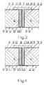
- Fig. 1 in horizontal cross-section double-winged Fire door, the passive wing of which has a non-metallic profile with a stop bar resting against active, non-winged wings
- Fig. 2 the horizontal cross-section of the fire door, in which the passive wing has a non-metallic profile with a stop bar and the active wing has a sheet stop
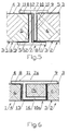
- Fig. 3 the horizontal cross-section of the fire door, in which the passive wing has a non-metallic profile with stop bar, whereas the active, non-wing wing has an insulating strip
- Fig. 1 in horizontal cross-section double-winged Fire door, the passive wing of which has a non-metallic profile with a stop bar resting against active, non-winged wings
- Fig. 2 the horizontal cross-section of the fire door, in which the passive wing has a non-metallic profile with a stop bar and the active wing has a sheet stop
- Fig. 3 the horizontal cross-section of the fire door, in which
- Fig. 4 The horizontal cross-section of the fire door, in which the passive wing has a non-metallic profile with stop bar and the active wing has a sheet metal stopper and an insulating strip
- Fig. 5 The horizontal cross-section of the fire door, in which both wings do not have metallic profiles with stop strips, however Fig. 6 shows the horizontal cross section of the fire door with non-metallic profile, the web has a lightweight core with fireproof enclosure.
- Two-wing fire door consists of a pivotable active wing 1 and a pivotable passive wing 2, which are placed on the hinge, not shown in the drawing.
- Each of the wings 1, 2 has two parallel pads 3 with basically flat face plates 4 made of sheet metal with transversely bent edges 5.
- the pads 3 can also be made of another material, for example made of wood or synthetic veneer.
- the filling 6 of non-combustible Därmedämmstoff most preferably mineral wool.
- the passive wing 2 of the fire door which on Fig. 1, 2 . 3 and 4 is shown, has on its edge vertically arranged profile 7 with T-like cross-section, which is arranged on the side of the active wing 1 .
- the profile 7 has two arms 8, 9 and a web 10 and is made of non-metallic fireproof fabric, most preferably made of refined gypsum with high density.
- the protruding arm 8 of the profile 7 forms a vertical stop bar 11 and its web 10 and the opposite arm 9 are attached to the edge of the wing 2 .
- the web 10 of the profile 7 is inserted in the lateral gap 12 of the wing 2 , wherein the gap is formed between the transverse edges 5 of the linings 3 of the wing 2 .
- the stop bar 11 abuts against the front plate 4 of the active, non-impact wing 1 .
- Fig. 3 shows a door where the stop bar 11 rests against the front plate 4 of the active, non-impact wing 1 .
- the heat-insulating strip 14 is inserted from non-metallic, refractory material, most preferably made of refined gypsum with high density.
- the stop bar 11 is located on the front plate 4 of the active wing 1 , where from the wing a vertical stop 13 protrudes from sheet metal.
- the stop 13 is located on the opposite side of the front plate 4 of the passive wing 2 .
- the heat-insulating strip 14 is inserted in the lateral gap 12 of the active wing 1 .
- each of the wings 1, 2 is provided with a profile 7 , the stop bar 11 rests against the adjacent wing 1 or 2 .
- Fig. 6 shows a similar door, where the active wing 1 has a protruding, vertical stop 13 made of sheet metal, whereas the passive wing 2 has on its edge a vertically arranged profile 7a with a T-like cross-section.
- the protruding arm 8 of this profile forms the vertical stop bar 11 and its web 10 a and the opposite arm 9 are attached to the edge of the wing 2 .
- the web 10a is made of non-metallic, relatively lightweight core 15 and from its angular enclosure 16.
- the core 15 is made of a fire-proof fabric, from cheapest mineral wool, but can also be made of combustible material, for example made of wood.
- Both arms 6, 9 of the profile 7a and the enclosure 16 of the core 15 are made of non-metallic, fire-proof fabric, most preferably made of refined gypsum with high density.
- the profiles 7, 7a and insulating strips 14 are glued to the edges of the wings 1, 2 and / or secured by means not shown countersunk screws. In order to achieve the required BranSearch the fire door, not shown in the drawing edges of each wing 1, 2 from the side of the frame, not shown, with non-metallic, fireproof profiles 7, 7a equipped with stop strips 11 .
Landscapes
- Engineering & Computer Science (AREA)
- Civil Engineering (AREA)
- Structural Engineering (AREA)
- Special Wing (AREA)
Abstract
Description
Der Gegenstand der Erfindung ist eine zweiflügelige Brandschutztür, welche für das Schließen von Verkehrsöffnungen in Gebäudewänden sowie für den Schutz der voneinander abgetrennten Räume vor Brandausbreitung dient.The subject of the invention is a double-leaf fire door, which serves for the closing of traffic openings in building walls and for the protection of the separated rooms from fire spread.
Relevante zweiflügelige Brandschutztüre sind aus
Bekannt ist eine zweiflügelige Brandschutztür mit einem schwenkbaren, aktiven Flügel und einem schwenkbaren, passiven Flügel, welche in einem festen Blendrahmen mittels Scharnieren eingesetzt sind. Jeder Flügel hat am Umfang einen rechteckigen Metallrahmen. Innerhalb des Metallrahmens befindet sich thermoisolierende Ausfüllung aus nicht brennbarem Stoff, am günstigsten aus Mineralwolle oder Gips. Diese Ausfüllung ist mittels paralleler Blechbeläge bedeckt, welche den Flügelrahmen beiderseitig abschließen. Darüber hinaus bekannt ist eine zweiflügelige rahmenlose Brandschutztür. Jeder Flügel dieser Brandschutztür hat zwei parallele, grundsätzlich flache Blechbeläge mit quer abgeknickten Rändern. Der Raum zwischen den Blechbelägen ist mit einem nicht brennbaren Wärmedämmstoff ausgefüllt. In den beiden bekannten Lösungen ragt aus dem senkrechten Flügelrand eine Anschlagleiste aus Blech heraus, welche an den Blechbelag des benachbarten Flügels anliegt. Im Fall eines Brandes auf der brandnahen Seite der Brandschutztür entsteht eine bedeutsam höhere Temperatur als auf der gegenüberliegenden Seite. Infolgedessen die Flügelrahmen aus Metall oder deren Anschlagleisten aus Blech sich verbiegen, wonach die Brandschutztür die geforderte Dichtheit verliert.A two-wing fire door with a pivotable, active wing and a pivotable, passive wing, which are inserted in a fixed frame by means of hinges, is known. Each wing has a rectangular metal frame on the circumference. Within the metal frame is thermo-insulating filling of non-combustible material, most preferably mineral wool or gypsum. This filling is covered by parallel sheet metal coverings, which complete the sash frame on both sides. In addition, a double-leaf frameless fire door is known. Each wing of this fire door has two parallel, generally flat sheet metal coverings with transversely bent edges. The space between the sheet metal is filled with a non-combustible thermal insulation material. In the two known solutions protrudes from the vertical edge of the wing a stop bar made of sheet metal, which rests against the sheet metal of the adjacent wing. In the case of a fire on the fire side of the fire door creates a significantly higher temperature than on the opposite side. As a result, the casement of metal or its stop strips of sheet metal bend, after which the fire door loses the required tightness.
Zweiflügelige Brandschutztür mit schwenkbarem, aktiven Flügel und schwenkbarem, passiven Flügel, von welchen jede zwei parallele, grundsätzlich flache Beläge mit quer geknickten Rändern haben, dagegen der Raum zwischen den Belägen ist mit nicht brennbarem Wärmedämmstoff ausgefüllt und wenigstens ein der Flügel hat an seinem Rand eine senkrechte Anschlagleiste, welche an den Belag des benachbarten Flügels anliegt, ist gemäß der Erfindung dadurch gekennzeichnet, daß die Anschlagleiste einen Arm eines T-ähnlichen Profils bildet, welches aus nicht metallischem brandsicheren Stoff hergestellt ist, wobei der Steg und der gegenüberliegende Arm dieses Profils am Rand des Flügels befestigt sind. Der Steg des Profils ist am günstigsten im Seitenspalt des Flügels eingesetzt, welcher zwischen den quer geknickten Rändern dessen Belägen besteht. In der günstigen Lösung ist das Profil mit dem passiven Flügel verbunden. Die Anschlagleiste dieses Profils liegt am günstigsten an den aktiven, anschlaglosen Flügel an. In einer anderen günstigen Lösung liegt die Anschlagleiste des Profils an den aktiven Flügel an, aus welchem ein senkrechter Anschlag herausragt, der an den passiven Flügel anliegt. In einer noch anderen günstigen Lösung liegt die Anschlagleiste des Profils an den aktiven, anschlaglosen Flügel an, in dessem Seitenspalt eine Dämmleiste aus nicht metallischem, brandsicheren Stoff eingesetzt ist. In einer noch anderen günstigen Lösung liegt die Anschlagleiste des Profils an den aktiven Flügel an, in dessem Seitenspalt eine Dämmleiste aus nicht metallischem, brandsicheren Stoff eingesetzt ist und aus welchem ein senkrechter Anschlag herausragt, der an den passiven Flügel anliegt. Günstig ist auch, wenn jeder der Flügel ein Profil hat, welchen Anschlagleiste an den benachbarten Flügel anliegt. Die zweiflügelige Brandschutztür in ihrer zweiten Ausführung gemäß der Erfindung ist dadurch gekennzeichnet, daß die Anschlagleiste einen Arm eines T-ähnlichen Profils bildet und der gegenüberliegende Arm und der Steg dieses Profils sind am Rand des Flügels befestigt, wobei der Steg aus nicht metallischen, verhältnismäßig leichten Kern mit Umfassung besteht und beide Arme des Profils sowie die Umfassung des Kerns aus nicht metallischem brandsicheren Stoff besteht. In der günstigen Lösung der Erfindung ist der Kern des Stegs aus brandsicherem Stoff hergestellt, obwohl er auch aus brennbarem Stoff sein kann.Double-leaf fire door with pivoting, active leaf and pivoting passive wing, each of which has two parallel, generally flat coverings with transversely folded edges, while the space between the coverings is filled with non-combustible thermal insulation material and at least one of the wings has at its edge vertical stop bar, which rests against the lining of the adjacent wing, according to the invention is characterized in that the stop bar forms an arm of a T-like profile, which is made of non-metallic fireproof fabric, wherein the web and the opposite arm of this profile are attached to the edge of the wing. The web of the profile is best used in the side gap of the wing, which consists between the transversely folded edges of its coverings. In the favorable solution, the profile is connected to the passive wing. The stop bar of this profile is best located on the active, non-impact wing. In another favorable solution, the stop bar of the profile is applied to the active wing, from which protrudes a vertical stop, which bears against the passive wing. In yet another favorable solution, the stop bar of the profile abuts against the active, non-stop wing, in whose side gap an insulating strip of non-metallic, fire-proof material is inserted. In yet another favorable solution, the stop bar of the profile is applied to the active wing, in whose side gap an insulating strip of non-metallic, fireproof fabric is used and from which protrudes a vertical stop, which rests against the passive wing. It is also beneficial if each of the wings has a profile, which stop bar rests against the adjacent wing. The double-leaf fire door in its second embodiment according to the invention is characterized in that the stop bar forms an arm of a T-like profile and the opposite arm and the web of this profile are attached to the edge of the wing, the web of non-metallic, relatively light Core consists of enclosure and consists of both arms of the profile and the enclosure of the core of non-metallic fireproof material. In the favorable solution of the invention, the core of the web is made of fireproof material, although it may also be made of combustible material.
Dank der Anwendung der Anschlagleiste aus nicht metallischem, brandsicheren Stoff, die Brandschutztür gemäß der Erfindung ist durch hohe Beständigkeit gegen hohe Temperaturen und unmittelbare Brandeinwirkung gekennzeichnet.Thanks to the application of the stop bar made of non-metallic, fire-proof material, the fire door according to the invention is characterized by high resistance to high temperatures and direct fire.
Der Gegenstand der Erfindung ist am Ausführungsbeispiel auf der Zeichnung dargestellt, wo
Zweiflügelige Brandschutztür gemäß Erfindung besteht aus einem schwenkbaren aktiven Flügel 1 sowie aus einem schwenkbaren passiven Flügel 2, welche auf den auf der Zeichnung nicht gezeigten Scharnieren aufgesetzt sind. Jeder der Flügel 1, 2 hat zwei parallele Beläge 3 mit grundsätzlich flachen Stirnplatten 4 aus Blech mit quer geknickten Rändern 5. Die Beläge 3 können auch aus einem anderen Stoff hergestellt werden, zum Beispiel aus Holz- oder Synthetikfurnier. Im Raum zwischen den Belägen 3 befindet sich die Ausfüllung 6 aus nicht brennbarem Därmedämmstoff, am günstigsten aus Mineralwolle. Der passive Flügel 2 der Brandschutztür, welcher auf
- 1 -1 -
- Flügelwing
- 2 -2 -
- Flügelwing
- 3 - 3 -
- Belagcovering
- 4 - 4 -
- Stirnplattefaceplate
- 5 - 5 -
- Randedge
- 6 - 6 -
- Ausfüllungfilling
- 7 -7 -
- Profilprofile
- 7a -7a -
- Profilprofile
- 8 -8th -
- Armpoor
- 9 -9 -
- Armpoor
- 10 -10 -
- Stegweb
- 10a -10a -
- Stegweb
- 11 - 11 -
- Anschlagleistestop bar
- 12 - 12 -
- Seitenspaltside gap
- 13 - 13 -
- Anschlagattack
- 14 - 14 -
- Wärmedämmleistethermal insulation strip
- 15 - 15 -
- Kerncore
- 16 - 16 -
- Umfassungencirclement
Claims (11)
- The double leaf doors with a tilting operative leaf and a tilting passive leaf, of which each has two parallel, fundamentally flat facings with crosswise bent edges, whereas the space between the facings is filled with non-combustible thermal insulation material and at least one of the leafs has vertical door stop strip on its rim, adhering to the facing of the neighbouring door leaf, characterised in that the section's (7) arm (8) with a cross-section resembling letter T constitutes the door stop strip (11), manufactured from a non-metallic fire resistant material, whereby the web (10) and the opposite arm (9) of this section are fixed on the rim of the leaf (1, 2).
- The doors, following claim 1, characterised in that the web (10) of the section (7) is affixed within the lateral gap (12) of the leaf (1, 2), created between the crosswise bended edges (5) of its facings (3).
- The doors, following claim 3, characterised in that the section (7) is connected with the passive leaf (2).
- The doors, following claim 1 or 2, characterised in that the door stop strip (11) of the section (7) adheres to the active, tilting leaf (1).
- The doors, following claim 3, characterised in that the door stop strip (11) of the section (7) adheres to the active leaf (1) from which protrudes a vertical door stop (13), adhering to the passive leaf (2).
- The doors, following claim 3, characterised in that the door stop strip (11) of the section (7) adheres to the active, non-door stop strip leaf (1), in which its lateral gap (12) is affixed a thermal insulation strip (14) manufactured from a non-metallic fire resistant material.
- The doors, following claim 3, characterised in that the door stop strip (11) of the section (7) adheres to the active, non-door stop strip leaf (1), in which its lateral gap (12) is affixed a thermal insulation strip (14) manufactured from a non-metallic fire resistant material and from which protrudes a vertical door stop (13), adhering to the passive leaf (2).
- The doors, following claim 1 or 2, characterised in that each of the leafs (1, 2) has a section (7), which door stop strip (11) adheres to the neighbouring leaf (1 or 2)
- The double leaf doors with a tilting operative leaf and a tilting passive leaf, of which each has two parallel, fundamentally flat facings with crosswise bent edges, whereas the space between the facings is filled with non-combustible thermal insulation material and at least one of the leafs has vertical door stop strip on its rim, adhering to the facing of the neighbouring door leaf, characterised in that the section's (7a) arm (8) with a cross-section resembling letter T constitutes the door stop strip (11), and the opposite arm (9) and the web (10a) of the section are fixed on the rim of the leaf (1, 2) whereby the web (10a) consists of a non-metallic, relatively light core (15) and the clamping ring (16) surrounding it and both arms (8,9) of the section (7a) and the clamping ring (16) of the core (15) are manufactured from a non- metallic fire resistant material.
- The doors, following claim 9, characterised in that the core (15) of the web (10a) is manufactured from a fire resistant material.
- The doors, following claim 9, characterised in that the core (15) of the web (10a) is manufactured from a combustible material.
Priority Applications (1)
| Application Number | Priority Date | Filing Date | Title |
|---|---|---|---|
| PL07460027T PL2000625T3 (en) | 2007-06-04 | 2007-10-15 | Double leaf fire door |
Applications Claiming Priority (1)
| Application Number | Priority Date | Filing Date | Title |
|---|---|---|---|
| PL382573A PL210827B1 (en) | 2007-06-04 | 2007-06-04 | Fire two-wing doors |
Publications (3)
| Publication Number | Publication Date |
|---|---|
| EP2000625A2 EP2000625A2 (en) | 2008-12-10 |
| EP2000625A3 EP2000625A3 (en) | 2011-04-27 |
| EP2000625B1 true EP2000625B1 (en) | 2012-04-18 |
Family
ID=39047762
Family Applications (1)
| Application Number | Title | Priority Date | Filing Date |
|---|---|---|---|
| EP07460027A Not-in-force EP2000625B1 (en) | 2007-06-04 | 2007-10-15 | Double leaf fire door |
Country Status (5)
| Country | Link |
|---|---|
| EP (1) | EP2000625B1 (en) |
| AT (1) | ATE554259T1 (en) |
| DK (1) | DK2000625T3 (en) |
| ES (1) | ES2386265T3 (en) |
| PL (2) | PL210827B1 (en) |
Families Citing this family (1)
| Publication number | Priority date | Publication date | Assignee | Title |
|---|---|---|---|---|
| DE102014108205A1 (en) * | 2014-06-11 | 2015-12-17 | IsoBouw Dämmtechnik GmbH | Fire protection kit with a fall protection for an inserted into a wall opening frame, in particular window or door frame |
Family Cites Families (3)
| Publication number | Priority date | Publication date | Assignee | Title |
|---|---|---|---|---|
| GB2270495A (en) * | 1992-09-08 | 1994-03-16 | Timber Technology Limited | Doors |
| FR2780437B1 (en) * | 1998-06-30 | 2000-09-29 | Malerba Dugelet | ANTI-FINGER CLIP, APPLIED TRIM AND PANEL IMPLEMENTING IT |
| NL1014421C2 (en) * | 1999-03-02 | 2000-09-14 | Alprokon Promotie Ontwikk Bv | Double door assembly comprises two profiles, each with body part fittable against head door end edge and cover rib fitted crossways and bridging over space between opposing door end edges |
-
2007
- 2007-06-04 PL PL382573A patent/PL210827B1/en unknown
- 2007-10-15 PL PL07460027T patent/PL2000625T3/en unknown
- 2007-10-15 EP EP07460027A patent/EP2000625B1/en not_active Not-in-force
- 2007-10-15 ES ES07460027T patent/ES2386265T3/en active Active
- 2007-10-15 DK DK07460027.1T patent/DK2000625T3/en active
- 2007-10-15 AT AT07460027T patent/ATE554259T1/en active
Also Published As
| Publication number | Publication date |
|---|---|
| EP2000625A2 (en) | 2008-12-10 |
| PL382573A1 (en) | 2008-12-08 |
| PL2000625T3 (en) | 2012-09-28 |
| EP2000625A3 (en) | 2011-04-27 |
| DK2000625T3 (en) | 2012-07-23 |
| PL210827B1 (en) | 2012-03-30 |
| ES2386265T3 (en) | 2012-08-14 |
| ATE554259T1 (en) | 2012-05-15 |
Similar Documents
| Publication | Publication Date | Title |
|---|---|---|
| EP1115953B1 (en) | Fire wall | |
| EP3080375B2 (en) | Device for closing an opening in a building | |
| EP0590236B2 (en) | Fire-resistant structural member | |
| EP0549769B1 (en) | Fire-resistant glass partition | |
| EP1793073B1 (en) | Building element in flame resistant implementation | |
| EP2581538B1 (en) | Profile-free flame-retardant glazing with pivoting door | |
| DE2439034B2 (en) | AGAINST HEAT RESISTANT GLAZING | |
| DE19635409B4 (en) | Glass door for fire protection purposes and method for producing a glass door for fire protection purposes | |
| EP2427621A1 (en) | Door, particularly fire protection door, having a door rabbet | |
| EP1586734B1 (en) | Glazed fire resistant door | |
| EP2000625B1 (en) | Double leaf fire door | |
| EP2657012B1 (en) | Frame-free fire protection all-glass door | |
| DE9321360U1 (en) | Fire retardant component | |
| EP2594724B1 (en) | Door or window that prevents break-in | |
| EP2000624B1 (en) | Fire resistant partition | |
| DE10110795B4 (en) | Edging profile for a fire and / or smoke protection | |
| EP3478919B1 (en) | Glass fire protection door having a lock case | |
| AT9854U1 (en) | FIRE PROTECTION ELEMENT FOR DOOR OR WINDOW WING | |
| EP1435424B1 (en) | Glass wall | |
| DE19957026C2 (en) | Fire-proof glazing with glass retaining strip attachment | |
| DE2942559A1 (en) | Fire-damping door construction - has metal leaf frame and layers of material expanded by heat in peripheral portion | |
| EP3604726B1 (en) | Door frame or door | |
| DE4345204A1 (en) | Frame profile, in particular aluminium frame profile, for safety windows, doors and/or wall elements | |
| DE10115970B4 (en) | Frame, in particular for a fire door | |
| EP1764451B1 (en) | Fitting for a fire gate installation |
Legal Events
| Date | Code | Title | Description |
|---|---|---|---|
| PUAI | Public reference made under article 153(3) epc to a published international application that has entered the european phase |
Free format text: ORIGINAL CODE: 0009012 |
|
| 17P | Request for examination filed |
Effective date: 20071025 |
|
| AK | Designated contracting states |
Kind code of ref document: A2 Designated state(s): AT BE BG CH CY CZ DE DK EE ES FI FR GB GR HU IE IS IT LI LT LU LV MC MT NL PL PT RO SE SI SK TR |
|
| AX | Request for extension of the european patent |
Extension state: AL BA HR MK RS |
|
| PUAL | Search report despatched |
Free format text: ORIGINAL CODE: 0009013 |
|
| AK | Designated contracting states |
Kind code of ref document: A3 Designated state(s): AT BE BG CH CY CZ DE DK EE ES FI FR GB GR HU IE IS IT LI LT LU LV MC MT NL PL PT RO SE SI SK TR |
|
| AX | Request for extension of the european patent |
Extension state: AL BA HR MK RS |
|
| RAP1 | Party data changed (applicant data changed or rights of an application transferred) |
Owner name: MALKOWSKI, MARCIN Owner name: MALKOWSKA, MAGDALENA Owner name: MALKOWSKA, RENATA |
|
| RIN1 | Information on inventor provided before grant (corrected) |
Inventor name: MALKOWSKI, MARCIN Inventor name: MALKOWSKA, MAGDALENA Inventor name: MALKOWSKA, RENATA |
|
| GRAP | Despatch of communication of intention to grant a patent |
Free format text: ORIGINAL CODE: EPIDOSNIGR1 |
|
| AKX | Designation fees paid |
Designated state(s): AT BE BG CH CY CZ DE DK EE ES FI FR GB GR HU IE IS IT LI LT LU LV MC MT NL PL PT RO SE SI SK TR |
|
| GRAS | Grant fee paid |
Free format text: ORIGINAL CODE: EPIDOSNIGR3 |
|
| GRAA | (expected) grant |
Free format text: ORIGINAL CODE: 0009210 |
|
| AK | Designated contracting states |
Kind code of ref document: B1 Designated state(s): AT BE BG CH CY CZ DE DK EE ES FI FR GB GR HU IE IS IT LI LT LU LV MC MT NL PL PT RO SE SI SK TR |
|
| REG | Reference to a national code |
Ref country code: GB Ref legal event code: FG4D |
|
| REG | Reference to a national code |
Ref country code: CH Ref legal event code: EP |
|
| REG | Reference to a national code |
Ref country code: IE Ref legal event code: FG4D Free format text: LANGUAGE OF EP DOCUMENT: GERMAN |
|
| REG | Reference to a national code |
Ref country code: AT Ref legal event code: REF Ref document number: 554259 Country of ref document: AT Kind code of ref document: T Effective date: 20120515 |
|
| REG | Reference to a national code |
Ref country code: DE Ref legal event code: R096 Ref document number: 502007009724 Country of ref document: DE Effective date: 20120614 |
|
| REG | Reference to a national code |
Ref country code: DK Ref legal event code: T3 |
|
| REG | Reference to a national code |
Ref country code: ES Ref legal event code: FG2A Ref document number: 2386265 Country of ref document: ES Kind code of ref document: T3 Effective date: 20120814 |
|
| REG | Reference to a national code |
Ref country code: NL Ref legal event code: T3 |
|
| LTIE | Lt: invalidation of european patent or patent extension |
Effective date: 20120418 |
|
| REG | Reference to a national code |
Ref country code: PL Ref legal event code: T3 |
|
| PG25 | Lapsed in a contracting state [announced via postgrant information from national office to epo] |
Ref country code: IS Free format text: LAPSE BECAUSE OF FAILURE TO SUBMIT A TRANSLATION OF THE DESCRIPTION OR TO PAY THE FEE WITHIN THE PRESCRIBED TIME-LIMIT Effective date: 20120818 Ref country code: CY Free format text: LAPSE BECAUSE OF FAILURE TO SUBMIT A TRANSLATION OF THE DESCRIPTION OR TO PAY THE FEE WITHIN THE PRESCRIBED TIME-LIMIT Effective date: 20120418 Ref country code: SE Free format text: LAPSE BECAUSE OF FAILURE TO SUBMIT A TRANSLATION OF THE DESCRIPTION OR TO PAY THE FEE WITHIN THE PRESCRIBED TIME-LIMIT Effective date: 20120418 Ref country code: LT Free format text: LAPSE BECAUSE OF FAILURE TO SUBMIT A TRANSLATION OF THE DESCRIPTION OR TO PAY THE FEE WITHIN THE PRESCRIBED TIME-LIMIT Effective date: 20120418 Ref country code: FI Free format text: LAPSE BECAUSE OF FAILURE TO SUBMIT A TRANSLATION OF THE DESCRIPTION OR TO PAY THE FEE WITHIN THE PRESCRIBED TIME-LIMIT Effective date: 20120418 |
|
| PG25 | Lapsed in a contracting state [announced via postgrant information from national office to epo] |
Ref country code: GR Free format text: LAPSE BECAUSE OF FAILURE TO SUBMIT A TRANSLATION OF THE DESCRIPTION OR TO PAY THE FEE WITHIN THE PRESCRIBED TIME-LIMIT Effective date: 20120719 Ref country code: SI Free format text: LAPSE BECAUSE OF FAILURE TO SUBMIT A TRANSLATION OF THE DESCRIPTION OR TO PAY THE FEE WITHIN THE PRESCRIBED TIME-LIMIT Effective date: 20120418 Ref country code: LV Free format text: LAPSE BECAUSE OF FAILURE TO SUBMIT A TRANSLATION OF THE DESCRIPTION OR TO PAY THE FEE WITHIN THE PRESCRIBED TIME-LIMIT Effective date: 20120418 Ref country code: PT Free format text: LAPSE BECAUSE OF FAILURE TO SUBMIT A TRANSLATION OF THE DESCRIPTION OR TO PAY THE FEE WITHIN THE PRESCRIBED TIME-LIMIT Effective date: 20120820 |
|
| PG25 | Lapsed in a contracting state [announced via postgrant information from national office to epo] |
Ref country code: CZ Free format text: LAPSE BECAUSE OF FAILURE TO SUBMIT A TRANSLATION OF THE DESCRIPTION OR TO PAY THE FEE WITHIN THE PRESCRIBED TIME-LIMIT Effective date: 20120418 Ref country code: RO Free format text: LAPSE BECAUSE OF FAILURE TO SUBMIT A TRANSLATION OF THE DESCRIPTION OR TO PAY THE FEE WITHIN THE PRESCRIBED TIME-LIMIT Effective date: 20120418 Ref country code: EE Free format text: LAPSE BECAUSE OF FAILURE TO SUBMIT A TRANSLATION OF THE DESCRIPTION OR TO PAY THE FEE WITHIN THE PRESCRIBED TIME-LIMIT Effective date: 20120418 Ref country code: SK Free format text: LAPSE BECAUSE OF FAILURE TO SUBMIT A TRANSLATION OF THE DESCRIPTION OR TO PAY THE FEE WITHIN THE PRESCRIBED TIME-LIMIT Effective date: 20120418 |
|
| PGFP | Annual fee paid to national office [announced via postgrant information from national office to epo] |
Ref country code: FR Payment date: 20121017 Year of fee payment: 6 |
|
| PLBE | No opposition filed within time limit |
Free format text: ORIGINAL CODE: 0009261 |
|
| STAA | Information on the status of an ep patent application or granted ep patent |
Free format text: STATUS: NO OPPOSITION FILED WITHIN TIME LIMIT |
|
| PGFP | Annual fee paid to national office [announced via postgrant information from national office to epo] |
Ref country code: GB Payment date: 20121005 Year of fee payment: 6 |
|
| 26N | No opposition filed |
Effective date: 20130121 |
|
| REG | Reference to a national code |
Ref country code: DE Ref legal event code: R097 Ref document number: 502007009724 Country of ref document: DE Effective date: 20130121 |
|
| PG25 | Lapsed in a contracting state [announced via postgrant information from national office to epo] |
Ref country code: MC Free format text: LAPSE BECAUSE OF NON-PAYMENT OF DUE FEES Effective date: 20121031 |
|
| REG | Reference to a national code |
Ref country code: CH Ref legal event code: PL |
|
| REG | Reference to a national code |
Ref country code: IE Ref legal event code: MM4A |
|
| PG25 | Lapsed in a contracting state [announced via postgrant information from national office to epo] |
Ref country code: LI Free format text: LAPSE BECAUSE OF NON-PAYMENT OF DUE FEES Effective date: 20121031 Ref country code: CH Free format text: LAPSE BECAUSE OF NON-PAYMENT OF DUE FEES Effective date: 20121031 Ref country code: BG Free format text: LAPSE BECAUSE OF FAILURE TO SUBMIT A TRANSLATION OF THE DESCRIPTION OR TO PAY THE FEE WITHIN THE PRESCRIBED TIME-LIMIT Effective date: 20120718 Ref country code: IE Free format text: LAPSE BECAUSE OF NON-PAYMENT OF DUE FEES Effective date: 20121015 |
|
| PG25 | Lapsed in a contracting state [announced via postgrant information from national office to epo] |
Ref country code: MT Free format text: LAPSE BECAUSE OF FAILURE TO SUBMIT A TRANSLATION OF THE DESCRIPTION OR TO PAY THE FEE WITHIN THE PRESCRIBED TIME-LIMIT Effective date: 20120418 |
|
| PG25 | Lapsed in a contracting state [announced via postgrant information from national office to epo] |
Ref country code: TR Free format text: LAPSE BECAUSE OF FAILURE TO SUBMIT A TRANSLATION OF THE DESCRIPTION OR TO PAY THE FEE WITHIN THE PRESCRIBED TIME-LIMIT Effective date: 20120418 |
|
| PG25 | Lapsed in a contracting state [announced via postgrant information from national office to epo] |
Ref country code: LU Free format text: LAPSE BECAUSE OF NON-PAYMENT OF DUE FEES Effective date: 20121015 |
|
| GBPC | Gb: european patent ceased through non-payment of renewal fee |
Effective date: 20131015 |
|
| PG25 | Lapsed in a contracting state [announced via postgrant information from national office to epo] |
Ref country code: GB Free format text: LAPSE BECAUSE OF NON-PAYMENT OF DUE FEES Effective date: 20131015 Ref country code: HU Free format text: LAPSE BECAUSE OF FAILURE TO SUBMIT A TRANSLATION OF THE DESCRIPTION OR TO PAY THE FEE WITHIN THE PRESCRIBED TIME-LIMIT Effective date: 20071015 |
|
| REG | Reference to a national code |
Ref country code: FR Ref legal event code: ST Effective date: 20140630 |
|
| PG25 | Lapsed in a contracting state [announced via postgrant information from national office to epo] |
Ref country code: FR Free format text: LAPSE BECAUSE OF NON-PAYMENT OF DUE FEES Effective date: 20131031 |
|
| PGFP | Annual fee paid to national office [announced via postgrant information from national office to epo] |
Ref country code: DK Payment date: 20140905 Year of fee payment: 8 Ref country code: NL Payment date: 20140908 Year of fee payment: 8 |
|
| PGFP | Annual fee paid to national office [announced via postgrant information from national office to epo] |
Ref country code: ES Payment date: 20140908 Year of fee payment: 8 |
|
| PGFP | Annual fee paid to national office [announced via postgrant information from national office to epo] |
Ref country code: DE Payment date: 20140908 Year of fee payment: 8 |
|
| PGFP | Annual fee paid to national office [announced via postgrant information from national office to epo] |
Ref country code: AT Payment date: 20141021 Year of fee payment: 8 |
|
| PGFP | Annual fee paid to national office [announced via postgrant information from national office to epo] |
Ref country code: BE Payment date: 20141020 Year of fee payment: 8 |
|
| PGFP | Annual fee paid to national office [announced via postgrant information from national office to epo] |
Ref country code: PL Payment date: 20140905 Year of fee payment: 8 |
|
| PGFP | Annual fee paid to national office [announced via postgrant information from national office to epo] |
Ref country code: IT Payment date: 20151005 Year of fee payment: 9 |
|
| REG | Reference to a national code |
Ref country code: DE Ref legal event code: R119 Ref document number: 502007009724 Country of ref document: DE |
|
| REG | Reference to a national code |
Ref country code: DK Ref legal event code: EBP Effective date: 20151031 |
|
| REG | Reference to a national code |
Ref country code: AT Ref legal event code: MM01 Ref document number: 554259 Country of ref document: AT Kind code of ref document: T Effective date: 20151015 |
|
| REG | Reference to a national code |
Ref country code: NL Ref legal event code: MM Effective date: 20151101 |
|
| PG25 | Lapsed in a contracting state [announced via postgrant information from national office to epo] |
Ref country code: DE Free format text: LAPSE BECAUSE OF NON-PAYMENT OF DUE FEES Effective date: 20160503 |
|
| PG25 | Lapsed in a contracting state [announced via postgrant information from national office to epo] |
Ref country code: NL Free format text: LAPSE BECAUSE OF NON-PAYMENT OF DUE FEES Effective date: 20151101 Ref country code: AT Free format text: LAPSE BECAUSE OF NON-PAYMENT OF DUE FEES Effective date: 20151015 |
|
| PG25 | Lapsed in a contracting state [announced via postgrant information from national office to epo] |
Ref country code: DK Free format text: LAPSE BECAUSE OF NON-PAYMENT OF DUE FEES Effective date: 20151031 |
|
| PG25 | Lapsed in a contracting state [announced via postgrant information from national office to epo] |
Ref country code: PL Free format text: LAPSE BECAUSE OF NON-PAYMENT OF DUE FEES Effective date: 20151015 |
|
| PG25 | Lapsed in a contracting state [announced via postgrant information from national office to epo] |
Ref country code: ES Free format text: LAPSE BECAUSE OF NON-PAYMENT OF DUE FEES Effective date: 20151016 |
|
| PG25 | Lapsed in a contracting state [announced via postgrant information from national office to epo] |
Ref country code: BE Free format text: LAPSE BECAUSE OF NON-PAYMENT OF DUE FEES Effective date: 20151031 |
|
| PG25 | Lapsed in a contracting state [announced via postgrant information from national office to epo] |
Ref country code: IT Free format text: LAPSE BECAUSE OF NON-PAYMENT OF DUE FEES Effective date: 20161015 |
|
| REG | Reference to a national code |
Ref country code: ES Ref legal event code: FD2A Effective date: 20180710 |