EP2000602A2 - Verschlussbauteil und Vorrichtung damit - Google Patents
Verschlussbauteil und Vorrichtung damit Download PDFInfo
- Publication number
- EP2000602A2 EP2000602A2 EP08251960A EP08251960A EP2000602A2 EP 2000602 A2 EP2000602 A2 EP 2000602A2 EP 08251960 A EP08251960 A EP 08251960A EP 08251960 A EP08251960 A EP 08251960A EP 2000602 A2 EP2000602 A2 EP 2000602A2
- Authority
- EP
- European Patent Office
- Prior art keywords
- liquid
- drain hole
- drain
- closure assembly
- sink
- Prior art date
- Legal status (The legal status is an assumption and is not a legal conclusion. Google has not performed a legal analysis and makes no representation as to the accuracy of the status listed.)
- Withdrawn
Links
Images

Classifications
-
- E—FIXED CONSTRUCTIONS
- E03—WATER SUPPLY; SEWERAGE
- E03C—DOMESTIC PLUMBING INSTALLATIONS FOR FRESH WATER OR WASTE WATER; SINKS
- E03C1/00—Domestic plumbing installations for fresh water or waste water; Sinks
- E03C1/12—Plumbing installations for waste water; Basins or fountains connected thereto; Sinks
- E03C1/22—Outlet devices mounted in basins, baths, or sinks
- E03C1/23—Outlet devices mounted in basins, baths, or sinks with mechanical closure mechanisms
- E03C1/2302—Outlet devices mounted in basins, baths, or sinks with mechanical closure mechanisms the actuation force being transmitted to the plug via rigid elements
Definitions
- the invention to which this application relates is an assembly for use in the selective closing and opening of a drain hole provided within a sink, bath, shower tray or bidet or similar form of article and hereinafter referred to in a non-limiting manner as a sink.
- sinks are provided to allow the use of liquid held within a cavity formed in the same for washing purposes and, once the washing activity has ceased, to allow the removal of the liquid from the sink via at least one drain hole provided in the basin of the same.
- the drain hole is provided with a plug which can be selectively positioned in the drain hole in a tight seal therewith in order to prevent liquid passing into the drain hole from the sink, or removed from the drain hole to open the drain hole and allow liquid to leave the sink and flow into the drain. While plugs are still used, they are generally regarded as being unsightly and therefore at least one alternative system is used extensively.
- This alternative system utilises a plate like member which can be moved between a first, closed position in which the same seals against the periphery of or adjacent to the top face of the drain hole, and a second, open position in which the plate like member is raised from the drain hole to define a gap between the plate and drain hole and through which gap the liquid in the sink can pass into the drain hole to drain the liquid from the sink.
- the plate member can be provided with an external finish, such as for example, stainless steel or chrome, which is more pleasing to the eye than a normal plug.
- the movement of the plate can be achieved remotely from the plate location such that the user does not have to place their hands into what maybe a dirty liquid to move the cover from the closed to open position.
- the movement of the plate is achieved via a mechanical actuation assembly which typically comprises two interconnected rods mounted within the drain hole on the underside of the plate. At a distal end of the rods there is provided, typically at a location adjacent to the taps provided on the sink, a portion which is exposed to be actuated by the user or may be linked to a rotational member which can be actuated by the user. This means that the user can actuate the cover without having to place their hands into the body of water held in the sink.
- a mechanical actuation assembly typically comprises two interconnected rods mounted within the drain hole on the underside of the plate. At a distal end of the rods there is provided, typically at a location adjacent to the taps provided on the sink, a portion which is exposed to be actuated by the user or may be linked to a rotational member which can be actuated by the user. This means that the user can actuate the cover without having to place their hands into the body of water held in the sink.
- the aim of the present invention is to provide a closure assembly for selectively closing and opening a drain hole, and to provide the assembly in a form which allows greater options to be available in terms of the appearance of the drain hole and closure assembly and also to provide the closure assembly in a manner in which the same can not be easily removed.
- apparatus having a cavity for the collection of a body of liquid therein, said cavity including at least one drain hole leading to a drain pipe, and a closure assembly, said closure assembly including a member movable between a closed position in which the body of liquid can be collected and an open position in which liquid is allowed to drain through the drain pipe and wherein said member is located downstream from the drain hole.
- the said member is located in the drainpipe connected to the drain hole.
- the item has a cavity and is provided as part of a sink, bath or shower tray assembly, to which reference is hereon made in a non limiting manner.
- the member is provided as part of a closure assembly which includes actuating means to act on the member to move the same between the open and closed positions.
- the actuating means comprises one or more rods, which have a free end which can be actuated, directly by a user, or via an actuating member, with said actuation possible at an external location on the sink remote from the member.
- the said actuation location is such that the same can be used without the user having to bring their hand into contact with any liquid held in the cavity.
- the same is not easily accessible from the sink cavity and therefore the opportunity for the member to be stolen and render the sink unusable, is significantly reduced in comparison to conventional closures.
- a cover positioned with respect to the drain hole opening to define one or more apertures through which liquid can pass so as to allow the same to enter the drain hole.
- liquid can enter the drain hole regardless of whether the member is in the open or closed position. However, if the member is in the closed position, the liquid will only be able to enter the drain pipe until it reaches the position of the member in its sealing position, at which point no further movement of the liquid is possible along the drain pipe until the member is moved to the open position.
- the majority of the mechanism is located below the item in an enclosure.
- the enclosure is provided as an integral part of the item and can also be used to conceal other components of the sink.
- a horizontally sealing waste trap is utilised.
- the cover is formed as a sheet material body and the aperture or apertures which are provided, are formed between a periphery of the cover and the drain hole opening and/or surface of the sink adjacent to the drain hole opening.
- the drain hole opening is not readily apparent and in plan view, the apertures between the cover and cavity are not visible.
- the shape of at least the external surface of the cover is contoured to match the shape of the sink surface adjacent thereto.
- the material used to form the cover or at least form the external surface of the cover has a selected appearance which, although required to be resistant to damage from the liquid, can be selected from a wide range of possible materials and therefore can be selected to provide a range of particularly distinctive visual appearances which would not be possible using conventional closure means. This can be achieved as the cover is not required to perform a movement function.
- the cover is held in a fixed position with regard to the sink, regardless of whether liquid is being held in the sink or being drained therefrom.
- a closure assembly for an item in the form of a sink, bath, shower tray or bidet, said item having at least one drain hole formed therein and a drain pipe extending from said drain hole to allow liquid to drain from the item when the closure assembly is in an open position
- said closure assembly comprises a member which can be moved between an open, drainage, position and a closed, sealing, position, actuation means to allow the member to be moved between said positions and a cover, said cover provided in a fixed relationship with regard to the item to define at least one aperture through which liquid leaves the item and enters the drain pipe.
- the member is operated by the actuation means which extend to an external location on or adjacent to the item, at which location the user can operate the actuation means and hence selectively move the member.
- the member is located within the drain pipe at a spaced distance from said cover which is typically located at the drain hole opening into the drain pipe.
- apparatus for the control of the flow of liquid through a drain hole from a sink, shower tray, bidet or bath leading to a drain pipe, said apparatus including a closure assembly, said closure assembly including a member movable between a closed position in which the liquid is prevented from draining and an open position in which liquid can drain and wherein said member is located downstream from the opening into the drain hole in both closed and open positions.
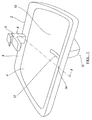
- FIG. 1 there is illustrated a sink in accordance with the invention, in the form of a bathroom sink.
- the sink 2 includes a cavity 4 in which water can be poured from one or more tap assemblies 6 which are mounted at the rim 8 of the cavity at the rear as shown.
- a cover 12 which can be of any shape, appearance as desired. It will therefore be seen that from the normal viewpoint of a user of the sink in direction 14, all that is apparent to them is the cover 12.
- There is no movable assembly or removable part provided within the cavity which is contrary to the conventional sink wherein there is either a plug or a plate which can be raised or lowered between an open and closed position to allow the drainage or collecting of liquid in the sink.
- an enclosure 16 On the underside of the sink or basin, there is provided an enclosure 16, said enclosure acting as the masking means for the closure assembly provided for the sink.
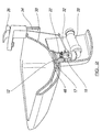
- the drainage assembly comprises a drain hole 17 which leads into a drainpipe 18 and waste trap 20 which, in this case, depend vertically downwardly and then horizontally to allow the same to be provided within the enclosure 16 on the underside of the sink
- the closure assembly for the sink which is shown in more detail in Figures 3a and b.
- the closure assembly comprises a member 22, which comprises a plate-like portion 24 and a downwardly depending rod 26.
- the base or free end 28 of the rod 26, is contactable with an actuation means 30, which comprises, in this embodiment, first and second interconnected rods 32, 34.
- One end of the actuation means contacts with the free end 28 of the member 26 and the other end is connected to a lever 36 which is provided externally for user actuation and hence allows the user to move the closure assembly between open and closed positions.
- the member 22 is provided to be raised and lowered so as to move the same between a lowered sealing position shown in Figure 3a and a raised drainage position shown in Figure 3b .
- the member portion 24 seals against a peripheral lip 38 of the drainpipe and in a drainage position, the member portion 24 is raised from the peripheral lip 38 so as to form a gap 40 between the same.
- water which is poured into the sink cavity 4 will enter into the portion 42 of the drainpipe through a gap 44 which is formed between the cover 12 and the external face 46 of the sink cavity 4, adjacent the drain hole opening 17.
- the actuation means 30 When it is required to drain the liquid from the basin cavity 4, the actuation means 30 is operated from lever 36 externally of the basin to cause the rods 32, 34 of the actuation means to move the member 22 from the sealed position to the open drainage position shown in Figure 3b , with the movement being as indicated by the arrow 48. In this position, the gap 40 which is formed between the member 22 and the peripheral lip 38 of the drainpipe, allows the flow of liquid therethrough and to continue along the remainder of the drainpipe and to the drainage system as indicated by the arrows 50.
- a further advantage of the present invention is that as the cover is the only portion which is viewable, the materials used for the remainder of the closure assembly which is held within the drainpipe, and which is not externally viewable, can be chosen with regard to functional and/or cost requirements rather than having to take into account any visual appearance implications.
Landscapes
- Engineering & Computer Science (AREA)
- Mechanical Engineering (AREA)
- Environmental & Geological Engineering (AREA)
- Health & Medical Sciences (AREA)
- Life Sciences & Earth Sciences (AREA)
- Hydrology & Water Resources (AREA)
- Public Health (AREA)
- Water Supply & Treatment (AREA)
- Domestic Plumbing Installations (AREA)
- Sink And Installation For Waste Water (AREA)
Applications Claiming Priority (1)
| Application Number | Priority Date | Filing Date | Title |
|---|---|---|---|
| GB0710673A GB0710673D0 (en) | 2007-06-05 | 2007-06-05 | Closure assembly |
Publications (2)
| Publication Number | Publication Date |
|---|---|
| EP2000602A2 true EP2000602A2 (de) | 2008-12-10 |
| EP2000602A3 EP2000602A3 (de) | 2012-10-03 |
Family
ID=38289836
Family Applications (1)
| Application Number | Title | Priority Date | Filing Date |
|---|---|---|---|
| EP08251960A Withdrawn EP2000602A3 (de) | 2007-06-05 | 2008-06-05 | Verschlussbauteil und Vorrichtung damit |
Country Status (2)
| Country | Link |
|---|---|
| EP (1) | EP2000602A3 (de) |
| GB (1) | GB0710673D0 (de) |
Cited By (1)
| Publication number | Priority date | Publication date | Assignee | Title |
|---|---|---|---|---|
| DE202012011346U1 (de) * | 2012-11-27 | 2014-03-05 | Duravit Ag | Sanitärwanne |
Family Cites Families (6)
| Publication number | Priority date | Publication date | Assignee | Title |
|---|---|---|---|---|
| GB656287A (en) * | 1948-11-01 | 1951-08-15 | C S A Ind Ltd | Improvements in or relating to domestic sinks or the like |
| AT375988B (de) * | 1983-05-11 | 1984-09-25 | Oespag Oesterr Sanitaer | Kombiniertes ueberlauf- und abflussventil |
| DE4032405A1 (de) * | 1990-09-14 | 1992-03-19 | Ideal Standard | Ablaufgarnitur |
| US6282730B1 (en) * | 1998-04-15 | 2001-09-04 | E-Ticket Enterprises, Llc | Magnetic stopper |
| US6154898A (en) * | 1999-05-19 | 2000-12-05 | Wcm Industries, Inc. | Wastewater drain control for fluid compartments |
| US6138297A (en) * | 1999-06-21 | 2000-10-31 | Harris; Robert J | Gravity ball valve and operating mechanism |
-
2007
- 2007-06-05 GB GB0710673A patent/GB0710673D0/en not_active Ceased
-
2008
- 2008-06-05 EP EP08251960A patent/EP2000602A3/de not_active Withdrawn
Cited By (1)
| Publication number | Priority date | Publication date | Assignee | Title |
|---|---|---|---|---|
| DE202012011346U1 (de) * | 2012-11-27 | 2014-03-05 | Duravit Ag | Sanitärwanne |
Also Published As
| Publication number | Publication date |
|---|---|
| GB0710673D0 (en) | 2007-07-11 |
| EP2000602A3 (de) | 2012-10-03 |
Similar Documents
| Publication | Publication Date | Title |
|---|---|---|
| CA2771221C (en) | Cable actuated drain | |
| US12031310B2 (en) | Pop-up drain stopper and actuator assembly | |
| US20060156460A1 (en) | Movement mechanism for moving a closure element for the purposes of sealing a waste outlet opening | |
| EP2859154A1 (de) | Raumsparendes wasserablaufsystem zur verwendung bei sanitärprodukten und mit verborgenem überlaufsystem | |
| EP2000602A2 (de) | Verschlussbauteil und Vorrichtung damit | |
| US6237168B1 (en) | Sink drain assembly including sink seal cap removal tool | |
| US544105A (en) | Sink and washtub | |
| JP2010077653A (ja) | 洗面装置 | |
| TWI691634B (zh) | 多功能地板排水器 | |
| KR20130064098A (ko) | 세면기 팝업밸브에 부착 사용되는 스트레이너 캡 | |
| KR101335632B1 (ko) | 선박용 화장실 유닛 | |
| JP4456961B2 (ja) | 浴槽の配管構造に用いられる目皿部材 | |
| JP6652413B2 (ja) | 操作装置 | |
| JP4941982B2 (ja) | オーバーフロー口の開閉構造 | |
| JP5486173B2 (ja) | 浴槽の排水栓装置 | |
| JP5455323B2 (ja) | 自動水栓付き洗面器ユニット | |
| JP7475606B2 (ja) | 配管構造 | |
| CA2797522A1 (en) | Remote controller unit for control of a valve of a drain fitting | |
| JPS63501024A (ja) | 間接出口と隠された排水機構とを有する衛生装置 | |
| JP5103073B2 (ja) | 手洗器 | |
| AU2016238907B2 (en) | Bathroom fittings | |
| WO2012030107A3 (ko) | 싱크대용 배수장치 | |
| CA2467491A1 (en) | Dishwasher float mounting bracket with retainer cover | |
| JP6712770B2 (ja) | 小便器および小便器システム | |
| EP3533942A1 (de) | Waschbeckenausstellventil |
Legal Events
| Date | Code | Title | Description |
|---|---|---|---|
| PUAI | Public reference made under article 153(3) epc to a published international application that has entered the european phase |
Free format text: ORIGINAL CODE: 0009012 |
|
| AK | Designated contracting states |
Kind code of ref document: A2 Designated state(s): AT BE BG CH CY CZ DE DK EE ES FI FR GB GR HR HU IE IS IT LI LT LU LV MC MT NL NO PL PT RO SE SI SK TR |
|
| AX | Request for extension of the european patent |
Extension state: AL BA MK RS |
|
| PUAL | Search report despatched |
Free format text: ORIGINAL CODE: 0009013 |
|
| AK | Designated contracting states |
Kind code of ref document: A3 Designated state(s): AT BE BG CH CY CZ DE DK EE ES FI FR GB GR HR HU IE IS IT LI LT LU LV MC MT NL NO PL PT RO SE SI SK TR |
|
| AX | Request for extension of the european patent |
Extension state: AL BA MK RS |
|
| RIC1 | Information provided on ipc code assigned before grant |
Ipc: E03C 1/23 20060101AFI20120827BHEP |
|
| AKX | Designation fees paid |
Designated state(s): AT BE BG CH CY CZ DE DK EE ES FI FR GB GR HR HU IE IS IT LI LT LU LV MC MT NL NO PL PT RO SE SI SK TR |
|
| STAA | Information on the status of an ep patent application or granted ep patent |
Free format text: STATUS: THE APPLICATION IS DEEMED TO BE WITHDRAWN |
|
| 18D | Application deemed to be withdrawn |
Effective date: 20130404 |