EP2000600A1 - Radlader - Google Patents
Radlader Download PDFInfo
- Publication number
- EP2000600A1 EP2000600A1 EP07738790A EP07738790A EP2000600A1 EP 2000600 A1 EP2000600 A1 EP 2000600A1 EP 07738790 A EP07738790 A EP 07738790A EP 07738790 A EP07738790 A EP 07738790A EP 2000600 A1 EP2000600 A1 EP 2000600A1
- Authority
- EP
- European Patent Office
- Prior art keywords
- arm
- brake
- valve
- switchover valve
- work oil
- Prior art date
- Legal status (The legal status is an assumption and is not a legal conclusion. Google has not performed a legal analysis and makes no representation as to the accuracy of the status listed.)
- Withdrawn
Links
- 230000004044 response Effects 0.000 claims description 14
- 230000002401 inhibitory effect Effects 0.000 claims description 8
- 238000010276 construction Methods 0.000 description 42
- 230000005540 biological transmission Effects 0.000 description 41
- 230000007246 mechanism Effects 0.000 description 29
- 230000001429 stepping effect Effects 0.000 description 25
- 230000009471 action Effects 0.000 description 18
- 239000004576 sand Substances 0.000 description 15
- 230000000694 effects Effects 0.000 description 9
- 230000008878 coupling Effects 0.000 description 7
- 238000010168 coupling process Methods 0.000 description 7
- 238000005859 coupling reaction Methods 0.000 description 7
- 238000006243 chemical reaction Methods 0.000 description 5
- 230000008602 contraction Effects 0.000 description 4
- 239000002361 compost Substances 0.000 description 3
- 230000008859 change Effects 0.000 description 2
- 238000001514 detection method Methods 0.000 description 2
- 238000010586 diagram Methods 0.000 description 2
- 238000006073 displacement reaction Methods 0.000 description 2
- 239000002828 fuel tank Substances 0.000 description 2
- 235000015250 liver sausages Nutrition 0.000 description 2
- 230000009347 mechanical transmission Effects 0.000 description 2
- 230000007935 neutral effect Effects 0.000 description 2
- 230000003213 activating effect Effects 0.000 description 1
- 230000008901 benefit Effects 0.000 description 1
- 230000009699 differential effect Effects 0.000 description 1
- 239000011888 foil Substances 0.000 description 1
- 239000000446 fuel Substances 0.000 description 1
- 238000010413 gardening Methods 0.000 description 1
- 230000002706 hydrostatic effect Effects 0.000 description 1
- 230000002093 peripheral effect Effects 0.000 description 1
- 230000035939 shock Effects 0.000 description 1
- 239000000725 suspension Substances 0.000 description 1
- 238000011144 upstream manufacturing Methods 0.000 description 1
Images







Classifications
-
- E—FIXED CONSTRUCTIONS
- E02—HYDRAULIC ENGINEERING; FOUNDATIONS; SOIL SHIFTING
- E02F—DREDGING; SOIL-SHIFTING
- E02F9/00—Component parts of dredgers or soil-shifting machines, not restricted to one of the kinds covered by groups E02F3/00 - E02F7/00
- E02F9/20—Drives; Control devices
- E02F9/22—Hydraulic or pneumatic drives
-
- B—PERFORMING OPERATIONS; TRANSPORTING
- B60—VEHICLES IN GENERAL
- B60T—VEHICLE BRAKE CONTROL SYSTEMS OR PARTS THEREOF; BRAKE CONTROL SYSTEMS OR PARTS THEREOF, IN GENERAL; ARRANGEMENT OF BRAKING ELEMENTS ON VEHICLES IN GENERAL; PORTABLE DEVICES FOR PREVENTING UNWANTED MOVEMENT OF VEHICLES; VEHICLE MODIFICATIONS TO FACILITATE COOLING OF BRAKES
- B60T1/00—Arrangements of braking elements, i.e. of those parts where braking effect occurs specially for vehicles
- B60T1/02—Arrangements of braking elements, i.e. of those parts where braking effect occurs specially for vehicles acting by retarding wheels
- B60T1/06—Arrangements of braking elements, i.e. of those parts where braking effect occurs specially for vehicles acting by retarding wheels acting otherwise than on tread, e.g. employing rim, drum, disc, or transmission or on double wheels
- B60T1/062—Arrangements of braking elements, i.e. of those parts where braking effect occurs specially for vehicles acting by retarding wheels acting otherwise than on tread, e.g. employing rim, drum, disc, or transmission or on double wheels acting on transmission parts
-
- B—PERFORMING OPERATIONS; TRANSPORTING
- B60—VEHICLES IN GENERAL
- B60T—VEHICLE BRAKE CONTROL SYSTEMS OR PARTS THEREOF; BRAKE CONTROL SYSTEMS OR PARTS THEREOF, IN GENERAL; ARRANGEMENT OF BRAKING ELEMENTS ON VEHICLES IN GENERAL; PORTABLE DEVICES FOR PREVENTING UNWANTED MOVEMENT OF VEHICLES; VEHICLE MODIFICATIONS TO FACILITATE COOLING OF BRAKES
- B60T7/00—Brake-action initiating means
-
- B—PERFORMING OPERATIONS; TRANSPORTING
- B60—VEHICLES IN GENERAL
- B60T—VEHICLE BRAKE CONTROL SYSTEMS OR PARTS THEREOF; BRAKE CONTROL SYSTEMS OR PARTS THEREOF, IN GENERAL; ARRANGEMENT OF BRAKING ELEMENTS ON VEHICLES IN GENERAL; PORTABLE DEVICES FOR PREVENTING UNWANTED MOVEMENT OF VEHICLES; VEHICLE MODIFICATIONS TO FACILITATE COOLING OF BRAKES
- B60T7/00—Brake-action initiating means
- B60T7/12—Brake-action initiating means for automatic initiation; for initiation not subject to will of driver or passenger
-
- E—FIXED CONSTRUCTIONS
- E02—HYDRAULIC ENGINEERING; FOUNDATIONS; SOIL SHIFTING
- E02F—DREDGING; SOIL-SHIFTING
- E02F9/00—Component parts of dredgers or soil-shifting machines, not restricted to one of the kinds covered by groups E02F3/00 - E02F7/00
- E02F9/02—Travelling-gear, e.g. associated with slewing gears
-
- E—FIXED CONSTRUCTIONS
- E02—HYDRAULIC ENGINEERING; FOUNDATIONS; SOIL SHIFTING
- E02F—DREDGING; SOIL-SHIFTING
- E02F9/00—Component parts of dredgers or soil-shifting machines, not restricted to one of the kinds covered by groups E02F3/00 - E02F7/00
- E02F9/20—Drives; Control devices
- E02F9/2025—Particular purposes of control systems not otherwise provided for
- E02F9/2037—Coordinating the movements of the implement and of the frame
-
- F—MECHANICAL ENGINEERING; LIGHTING; HEATING; WEAPONS; BLASTING
- F16—ENGINEERING ELEMENTS AND UNITS; GENERAL MEASURES FOR PRODUCING AND MAINTAINING EFFECTIVE FUNCTIONING OF MACHINES OR INSTALLATIONS; THERMAL INSULATION IN GENERAL
- F16D—COUPLINGS FOR TRANSMITTING ROTATION; CLUTCHES; BRAKES
- F16D65/00—Parts or details
- F16D65/14—Actuating mechanisms for brakes; Means for initiating operation at a predetermined position
- F16D65/16—Actuating mechanisms for brakes; Means for initiating operation at a predetermined position arranged in or on the brake
- F16D65/18—Actuating mechanisms for brakes; Means for initiating operation at a predetermined position arranged in or on the brake adapted for drawing members together, e.g. for disc brakes
- F16D65/186—Actuating mechanisms for brakes; Means for initiating operation at a predetermined position arranged in or on the brake adapted for drawing members together, e.g. for disc brakes with full-face force-applying member, e.g. annular
-
- F—MECHANICAL ENGINEERING; LIGHTING; HEATING; WEAPONS; BLASTING
- F16—ENGINEERING ELEMENTS AND UNITS; GENERAL MEASURES FOR PRODUCING AND MAINTAINING EFFECTIVE FUNCTIONING OF MACHINES OR INSTALLATIONS; THERMAL INSULATION IN GENERAL
- F16D—COUPLINGS FOR TRANSMITTING ROTATION; CLUTCHES; BRAKES
- F16D2121/00—Type of actuator operation force
- F16D2121/02—Fluid pressure
-
- F—MECHANICAL ENGINEERING; LIGHTING; HEATING; WEAPONS; BLASTING
- F16—ENGINEERING ELEMENTS AND UNITS; GENERAL MEASURES FOR PRODUCING AND MAINTAINING EFFECTIVE FUNCTIONING OF MACHINES OR INSTALLATIONS; THERMAL INSULATION IN GENERAL
- F16D—COUPLINGS FOR TRANSMITTING ROTATION; CLUTCHES; BRAKES
- F16D2121/00—Type of actuator operation force
- F16D2121/02—Fluid pressure
- F16D2121/12—Fluid pressure for releasing a normally applied brake, the type of actuator being irrelevant or not provided for in groups F16D2121/04 - F16D2121/10
Definitions
- the present invention relates to wheel loader having a machine body travelably supported on wheels and a work device mounted on the machine body.
- a wheel loader having a machine body travelably supported on front and rear wheels, and a work device supported to a front portion of the machine body, the work device including a boom having a base portion thereof supported to the machine body to be vertically pivotable, an arm pivotally connected to the leading end of the boom to be pivotable in the fore/aft direction, and a work implement pivotally attached to the leading end of the arm (see Patent Document 1).
- Patent Document 1 Japanese Patent Application "Kokai" No. 2005-171608
- the conventional wheel loaders e.g. one having a bucket, as the work implement, oriented to the front side, with the rear face side thereof being pivoted to the leading end of the arm, so that the bucket is capable of scooping/dumping operations, when a scooping operation for scooping a working target such as earth/sand, compost, snow, etc., or a digging operation is to be carried out, under a working posture where the pivot of the bucket is located downwardly of the pivot of the arm and the bottom face of the bucket faces the ground surface, the arm is pivotally operated to bring the bucket closer to the machine body and then from this condition, the arm is pivoted forward to cause the bucket to effect the scooping action.
- This mode of operation has the advantage that a great amount of earth/ sand or the like can be scooped by the bucket.
- the driver needs to confirm that the brake pedal has been stepped on and then to start operating the arm.
- the driver needs to confirm that the brake pedal has been stepped on and then to start operating the arm.
- the object of the present invention is to provide a wheel loader with improved operability.
- the wheel loader comprises:
- a hydraulic operating type brake for braking the wheels; wherein when said travel operating means is not operated and said arm has been pivoted, a portion of work oil fed to an arm cylinder for pivoting the arm is fed to said brake, so that said brake is actuated by this work oil.
- a work oil passageway extending from said arm cylinder to said brake incorporates therein a first switchover valve for allowing passage of the work oil from the arm cylinder to the brake when the travel operating means is not operated and for inhibiting said passage when the travel operating means is operated; and between said first switchover valve and said arm cylinder, there is provided a second switchover valve for allowing passage of the work oil from the arm cylinder to the first switchover valve when the arm is pivoted and for inhibiting said passage when the arm is not pivoted.
- a pressure relief circuit for relieving pressure in a pipe passage extending between the first switchover valve and the second switchover valve when the travel operating means is operated and the arm is not pivoted.
- a work oil passageway extending from said arm cylinder to said brake incorporates therein a first switchover valve for allowing passage of the work oil from the arm cylinder to the brake when the travel operating means is not operated and for inhibiting said passage when the travel operating means is operated; and between said first switchover valve and said brake, there is provided a second switchover valve for allowing passage of the work oil from the first switchover valve to said brake when the arm is pivoted and for inhibiting said passage when the arm is not pivoted.
- said second switchover valve is switched over in response to either a hydraulic signal sent from a pilot valve for operating an arm control valve for controlling said arm cylinder or an electric signal transmitted when an arm operating means for operating the arm is operated.
- said second switchover valve comprises a plurality of electromagnetic valves, including an electromagnetic switchover valve which is switched over for allowing passage of work oil if said arm operating means is operated to pivot the arm in one direction, and an electromagnetic switchover valve which is switched over for allowing passage of work oil if said arm operating means is operated to pivot the arm in the other direction.
- said brake is operable also in response to work oil fed by a traveling line brake operating means which is manually operated during traveling; and either the work oil fed by said traveling line brake operating means or the work oil fed from the arm cylinder side when the travel operating means is not operated and the arm is pivoted can be fed selectively via a shuttle valve.
- a differential device for transmitting power outputted from the engine to the right and left wheels; and said brake brakes the power inputted to said differential device.
- the brake As the brake is provided for braking the power inputted to the differential device, the brake can be applied while the torque is small. Hence, the load to the brake can be lessened, so that the automatic brake can be formed compact and also the right and left wheels can be braked by one automatic brake.
- FIG. 1 denotes a compact wheel loader for city use, to be used in home gardening for example.
- This wheel loader 1 includes a traveling body 2 disposed on the lower side and a swivel body 3 disposed on the upper side.
- the traveling body 2 comprises a wheel type traveling body 2 travelable by a pair of right and left front wheels 4 and a pair of right and left rear wheels 5, a traveling machine body 6 supported by the front and rear wheels 4, 5, an engine 7 mounted on the traveling machine body 6, a traveling line main transmission mechanism 8 for transmitting power of the engine 7 to the rear wheels 5, and a front wheel power transmission mechanism 9 for trnasmitt6ing power taken off the traveling line main power transmission mechanism 8 to the front wheels 4.
- the traveling machine body 6 includes a main frame 11 and a front frame 12 provided forwardly of this main frame 11.
- the main frame 11 mounts thereon the engine 7, a radiator 13, a battery 14, a swivel joint 15, a swivel motor 16, a swivel bearing 17, etc.
- the front frame 12 mounts thereon a fuel tank 18 for reserving fuel for the engine 7.
- a rear portion of the main frame 11 is supported on the right and left rear wheels 5, and a front portion of the front frame 12 is supported on the right and left front wheels 4. With these, the traveling machine body 6 is rendered travelable.
- the main frame 11 is comprised of plate members and includes an upper wall 19, right and left side walls 20 extending downward from right and left side edges of the upper wall 19, a front wall 21 fixed to the front ends of the upper wall 19 and the right and left side walls 20, and a rear wall 22 interconnecting rear end lower portions of the right and left side walls 20, with the main frame 11 being a downwardly opened.
- the engine 7 is arranged longitudinally at the right/left center side at a rear portion between the right and left side walls 20, with an axis of a crankshaft thereof being oriented along the fore/aft direction and also with an output shaft 23 thereof projecting forwardly.
- An upper end side of this engine 7 projects upward from an aperture defined in the upper wall 19 of the main frame 11.
- a cooing fan 25 is provided.
- the radiator 13 is disposed on the left side of the engine 7.
- a battery 14 is disposed on the right side of the engine 7. As shown in Fig. 4 , Fig.7 and Fig.
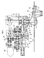
- the traveling line main power transmission mechanism 8 includes a traveling propelling shaft 26 receiving power from the engine 7, a hydrostatic transmission (“HST" hereinafter) 27 receiving the power from the traveling propelling shaft 26, a mechanical transmitting means 29 for transmitting the power from the HST 27 to a bevel pinion shaft 28, a rear wheel differential device 30 receiving the power from the bevel pinion shaft 28, and right and left final transmission devices 32 transmitting the power transmitted to the rear wheel differential device 30 to the right and left rear wheels 31.
- the traveling propelling shaft 26, the HST 27, the mechanical transmitting means 29, the bevel pinion shaft 28 and the rear wheel differential device 30 are disposed forwardly of the engine 7, and the final transmission devices 32 are arranged to extend from the sides of the rear wheel differential device 30 to the front lateral side of the engine 7.
- the traveling propelling shaft 26 is disposed along the fore/aft direction on the front side of the engine 7 and has its rear end side connected to a flywheel 33 connected to the output shaft 23 of the engine 7.
- the HST 27 includes an input shaft 36 for receiving the power from the engine 7, and an output shaft 37 for outputting power to the rear wheel differential mechanism 30, with the axes thereof being aligned with the fore/aft direction.
- This HST 27 includes a hydraulic pump 38 mounted on the input shaft 36 and a hydraulic motor 39 mounted on the output shaft 37, so that this transmission is configured such that the hydraulic motor 39 is driven by work oil fed by the hydraulic pump 38 driven by the input shaft 36 and the power is outputted from the output shaft 37 driven by the hydraulic motor 39.
- a casing 34 consists of a main body 40 having a rear face side thereof open and a lid body 41 closing the rear face side opening of the main body 40; and the input shaft 36 and the output shaft 47 project rearward from the lid body 41.
- the input shaft 36 of the HST 27 is arranged forwardly of the traveling propelling shaft 26 and coaxial with this propelling shaft 26 and operably coupled via coupling with the traveling propelling shaft 26.
- the hydraulic pump 38 comprises a variable displacement pump and its swash angle is variable by means of a swash plate controlling actuator 42. In operation, when the angle of the swash plate is changed, the flow amount of the work oil discharged to the hydraulic motor 39 is varied, so that the rotational speed the output shaft 37 (vehicle speed) can be changed. Further, this hydraulic pump 38 is capable of switching over the rotational direction of the output shaft 37 to the forward (forward rotation) or the reverse (reverse rotation) by changing the flow direction of the work oil discharged to the hydraulic motor 39.
- the swash plate controlling actuator 42 is controlled by a forward/reverse switchover means 43 comprised of a pilot operation switchover servo valve operated by pilot work oil.
- a forward/reverse switchover means 43 comprised of a pilot operation switchover servo valve operated by pilot work oil.
- a pilot operation pressure is developed at a forward side port 44 of this forward/reverse switchover means 43
- the swash pate of the hydraulic pump 38 is controlled so as to cause the output shaft 37 to be rotated forwardly.
- a pilot operation pressure is developed at a reverse side port 45 of this forward/reverse switchover means 43
- the swash pate of the hydraulic pump 38 is controlled so as to cause the output shaft 37 to be rotated in reverse. forwardly.
- a degree of pressure developed at the forward side port 44 or a reverse side port 45 the flow amount of the work oil discharged from the hydraulic pump 38 is controlled, thereby controlling the rotational speed of the output shaft 37.
- the hydraulic motor 39 comprises a variable displacement motor and has the angle of its swash plate variable in two steps by means of a high/low switchover actuator 46. So that, with change in the angle of the swash plate, the rotational power outputted from the output shaft 37 can be switched over between a high speed state and a low speed stage.
- the bevel pinion shaft 28 is disposed on the left side of a portion of the output shaft 37 of the HST 27 which portion projects rearward from the lid body 41 and disposed downwardly and in parallel with the same, the bevel pinion shaft 28 extending more rearward than the rear end of the output shaft 37 of the HST 27 and forming a bevel gear portion at the rear end thereof.
- the mechanical transmitting means 29, in the instant embodiment, comprises a gear transmission mechanism consisting of a drive side gear 47 mounted on the portion of the output shaft 37 of the HST 27 projecting rearward from the lid body 41 to be rotatable therewith and a driven side gear 48 mounted on the front end side of the bevel pinion shaft 28 to be rotatable therewith and meshed with the driven side gear 47, and this transmitting means is configured also as a speed reducing mechanism.
- this mechanical transmitting means 29 can also be an accelerating mechanism (speed changing mechanism) or a constant speed mechanism, and can be a mechanism for effecting power transmission such as coupling.
- the rear wheel differential device 30 is disposed rearwardly of the bevel pinion shaft 28 and forwardly of the left side of the engine 7 and has a differential output shaft 49 projecting to the right and left sides thereof.
- Rear axles 31 are disposed rearwardly of the differential output shaft 49 of the rear wheel differential device 30 and overlapped with the engine 7 in the side view, the rear wheel 5 being fixedly mounted on the outer end side of each one of the right and left rear axles 31 to be rotatable therewith.
- the final transmission device 32 comprises a gear transmission mechanism including a drive side gear 51 mounted on the right/left outer end portion of the differential output shaft 49 to be rotatable therewith and a driven side gear 52 mounted on the rear axle 31 to be rotatable therewith and this device is configured as a speed reducing mechanism.
- this final transmission device 32 too can be an accelerating mechanism (speed changing mechanism) or a constant speed mechanism.
- a housing 53 housing the flywheel 33, the rear wheel differential device 30, etc.
- a transmission case 54 housing the mechanical transmission means 29, etc.
- a casing 34 (the lid body 41 thereof) of the HST 27.
- the rear wheel differential device 30 the mechanical transmission means 39, the HST 27, etc. to be integral therewith.
- the housing 53, the transmission case 54 and the casing 34 are disposed between the right and left side walls 20 of the main frame 11.
- each one of the right and left transmission cases 55 housing the final transmission devices 32. And, to each one of the right and left final transmission case 55, the rear axle 31 is supported and the final transmission cases 55 are fixedly attached to the main frame 11. With each one of the right and left transmission cases 55, its front and right/left inner end side thereof is bolt-fixed to the lateral face of the housing 53 and a rear end side of each one of the right and left final transmission cases 55 is bolt-fixed to an upper portion side of the side wall 20 of the main frame 11.
- a cutout portion 56 open downward so as to engage from above the upper portion of the final transmission case 55, and the final transmission case 55 is bolt-fixed to the main frame side wall 20 around this cutout portion 56.
- the front portion side of the engine 7 is supported to the main frame 11 via the housing 53 and the final transmission case 55 and the rear portion side of the engine 7 is supported via a connecting plate or the like to the rear wall 22 of the main frame 11.
- the rear wheel differential device 30 is provided forwardly of the engine 7 and the rear axle 31 receiving the power from this rear wheel differential device 30 to rotate the rear wheel 5 is disposed at a position rearwardly of the differential output shaft 49 and overlapped with the engine 7 in the side view.
- the wheel loader 1 is formed compact in the fore/aft direction.
- a main pump 58 comprised of a double gear pump operably coupled to the front end side of the input shaft 36 of the HST 27 and driven by the power of the engine 7.
- the work oil from this main pump 58 is fed via the swivel joint 15 to various hydraulic actuators mounted on the wheel loader 1.
- this wheel loader 1 includes a sub pump 59 driven by the engine 7 to feed the work oil mainly for pilot pressure.
- the work oil for pilot pressure from this sub pump 59 is fed via the swivel joint 15 to the pilot valve mounted on the wheel loader 1 and the work oil from this sub pump 79 is fed also to the forward/reverse switchover means 43, etc.
- an oil pan 60 provided on the lower end side of the engine 7 is utilized as a work oil tank for reserving the work oil for the hydraulic components.
- the traveling main power transmission mechanism 8 includes a main brake (traveling brake, an automatic brake) 62 and a parking brake 63.
- the main brake 62 is a hydraulically operated brake for braking the traveling power transmitted , at the time of traveling or working, etc., from the HST 27 to the rear wheel differential device 30 and a front wheel differential device 61 to be described later (inputted to the rear wheel differential device 30 and the front wheel differential device 61).
- the parking brake 63 is a hydraulically operated brake for maintaining the front wheels 4 and the rear wheels 5 under stopped conditions at the time of parking. These brakes 62, 63 are disposed rearwardly of the drive side gear 47 of the mechanical transmitting means 29.
- the main brake 62 is housed in the transmission case 54.
- This main brake 62 includes a main brake case 64 fixed to the transmission case 54, a plurality of plates 66 housed in the main brake case 64 to be movable in the fore/aft direction and non-rotatable therein, brake discs 67 interposed between these brake plates 66, and main brake pistons 68 for bringing the brake discs 67 and the plates 66 into pressed contact with each other.
- the main brake case 64 is open rearward and into this main brake case 64, the rear end side of the output shaft 37 of the HST 27 is inserted. On this rear end side of the output shaft 37 inserted into the main brake case 64, the brake discs 67 are mounted to be axially (fore/aft direction) movable and rotatable in unison.
- the main brake pistons 68 are disposed in opposition to each other on the forward side of the front end side plates 66 and are housed inside rearwardly open piston housing portions 69 provided in the main brake case 64 to be movable in the fore/aft direction and to be projectable and retractable.
- the parking brake 63 is disposed rearwardly of the main brake 62 and this parking brake 63 includes a parking brake piston 71 housed inside a housing 53 and fixed to this housing 53, a piston support member 72 fixed to a parking brake case 70 and a spring 73 for pressing the parking brake piston 71 to bring the brake disc 67 and the plates 66 into pressed contact with each other.
- the parking brake case 70 is open forwardly and this parking brake case 70 is in communication with the main brake case 64.
- the piston support member 72 consists of a disc portion 74 disposed in opposition to the rear end plate 66 and a rod portion 75 projecting rearward from the center of this disc portion 74 and extending through a rear wall 70a of the parking brake case 70 to project rearward. And, the rod portion 75 is fixed to the rear wall 70a of the parking brake case.
- the parking brake piston 71 is mounted on the piston support member 72 to be movable in the fore/aft direction.
- the spring 73 is housed in a spring housing portion 76 in the parking brake piston 71 to be open rearward and is compressed between the parking brake piston 71 and the rear wall 70a of the parking brake piston 70.
- the parking brake 63 having the above-described construction in operation, at the time of stop of the engine 7 (parking), as the spring 73 presses the parking brake piston 71 to press the brake disc 67 and the plate 66 against the main brake case 64, the brake disc 67 and the plate 66 are compressed against each other, whereby the front wheels 4 and the rear wheels 5 are maintained under the stop condition.
- the work oil from the main pump 58 or the sub pump 59 is fed to the gap between the rear face of the disc portion 74 of the piston support member 72 and the parking brake piston 71, so that the hydraulic pressure of this work oil moves the parking brake piston 71 rearward against the urging force of the spring 73, thus releasing the pressed contact between the brake disc 67 and the plate 66.
- the main brake 62 is comprised of a disc brake and the brake disc 67 and the plate 66 of this disc brake are used also as the parking brake 63.
- a differential lock device 77 is a hydraulically operated differential lock device 77 configured such that as a differential lock shifter 78 operable in unison with a left side differential output shaft 49 is moved by the work oil toward the rear wheel differential device 30 against a return spring to mesh engaging teeth of this differential lock shifter 78 with engaging teeth provided in the rear wheel differential device 30 side, thereby to inhibit a differential action of the rear wheel differential device 30, thus providing the differential lock effect.
- a bearing attaching plate 79 formed of a thick plate. And, on this bearing attaching plate 79, there is fixedly attached an outer race of the swivel bearing 17 and the center of this swivel bearing 17 forms a swivel axis X.
- an inner toothed wheel and a pinion meshed with this inner toothed wheel is fixed to an output shaft of a swivel motor 16 comprised of a hydraulic motor fixed to the main frame 11, so that by this swivel motor 16, the inner race of the swivel bearing 17 can be turned about the swivel axis X.
- the front frame 12 of the traveling machine body 6 are formed of plate members, and includes an upper wall 81, right and left side walls 82 extending downward from the right and left side edges of this upper wall 81, and a connecting plate interconnecting the front portions of the right and left side walls 82, the front frame 12 being downwardly open on its rear side.
- a front axle case 83 On the front and lower side of the front frame 12, there is arranged a front axle case 83 oriented along the right/left direction, and on opposed fore/aft sides at the right/left center portion of this front axle case 83, there is arranged a front wheel bearing 84 supported to the front frame 12. To this fore/aft front wheel bearing 84, via a center pin, there is supported the front axle case 83 to be pivotable about a fore/aft axis. And, to the right and left sides of this front axle case 83, via gear cases or the like, the front wheels 4 are supported to be steerable.
- a steering cylinder 85 comprised of a hydraulic cylinder for steering the front wheels 4.
- This steering cylinder 85 includes piston rods 97 projecting from the right and left sides of the cylinder tube 86.
- Each right/left piston rod 97 is operably coupled with the front wheel 4 disposed on the same right/left side, and the steering cylinder 85 is controlled by a power steering controller 88 provided on the swivel body 3 side.
- the fuel tank 18 At the rear portion of the front frame 12 between the right and left side walls 82, there is arranged the fuel tank 18 for reserving the foil for the engine 7.
- the front wheel power transmission mechanism 9 for transmitting power to the front wheels 4 includes a front wheel power takeoff (PTO) shaft 89 connected to the driven side gear 48 of the mechanical transmitting means 29 and projecting forwardly from the transmission case 54, the front wheel differential device 61 provided inside the front axle case 83, a bevel pinion gear 90 for inputting the power to the front wheel differential device 61, a transmission shaft 91 for operably coupling this bevel pinion shaft 90 with the front wheel PTO shaft 98, and an unillustrated final speed reducing mechanism (transmission mechanism) for transmitting power from the differential output shaft 92 of the front wheel differential device 61 to the font wheels 4.
- PTO front wheel power takeoff
- the swivel body 3 includes a swivel machine body 93 supported on the traveling machine body 6 to be swivellable about a vertically extending swivel axis, a traveling line control device 94, a work device (ground work device, a digging work device) 95, a driver's seat 96, a control valve 97 for controlling the work device 95 and the swivel machine body 93, a counter weight 98 for obtaining weight balance relative to the work deice 95, a ROPS (roll-over protection system) 99, etc.
- a swivel machine body 93 supported on the traveling machine body 6 to be swivellable about a vertically extending swivel axis
- a traveling line control device 94 for controlling the work device 95 and the swivel machine body 93
- a control valve 97 for controlling the work device 95 and the swivel machine body 93
- a counter weight 98 for obtaining weight balance relative to
- the traveling machine body 6 and the swivel machine body 93 together constitute the machine body of the wheel loader 1.
- the swivel machine body 93 consists mainly of a swivel deck 101 fixedly attached to the inner race of the swivel bearing 17 to be swivellable about the swivel axis X, a pair of right and left masts (work device supports) 102 mounted erect on front portions of this swivel deck 101, and a driver's seat disposing frame body 103 provided at a rear portion of the swivel deck 101.
- the driver's seat disposing frame body 103 includes a support frame 104 fixed to the swivel deck 101, a seat deck 105 attached to this support frame 104 and mounting the driver's seat 96 to be pivoted forwardly and collapsible forwardly, and a weight attaching frame 106 to which the counter weight 98 is attached. And, to the support frame 104, the control valve 97 is fixedly attached.
- the traveling line control device 94 includes a steering wheel 108 and a brake pedal (traveling line brake operating means) 109 supported to a steering deck 107 disposed between the pair of right and left masts 102, and a traveling pedal (traveling operating means) 110 disposed forwardly of the driver's seat 96 and supported to the swivel deck 101.
- the steering wheel 108 is capable of controlling the power steering controller 88 and the brake pedal 109 has an upper end side thereof supported to the steering deck 107 to be pivotable about an axis extending along the right/left direction, so that the pedal can be controlled by a manual stepping operation.
- this brake pedal 109 is stepped on, work oil present in a master cylinder 111 is fed to the main brake 62 (the rear face side of the main brake piston 68 of the piston housing portion 69) thereby to activate the main brake 62.
- the brake pedal 109 is urged by a return spring to a position assumed thereby prior to the stepping operation, when released from the stepping operation.
- the work oil fed to the main brake 62 is returned to the master cylinder 111.
- the master cylinder 111 is disposed downwardly of the driver's seat 96 and in the vicinity thereof, there is provided a brake oil tank 112 for reserving work oil for the master cylinder 111.
- the traveling pedal 110 is pivotally supported, at its fore/aft intermediate portion, to a support shaft 113 having an axis extending along the right/left direction.
- the pedal 110 allows manual stepping operation either forwardly or rearwardly as seen from the driver, and the pedal 110 is urged to return to the neutral position upon release of such forward or rearward stepping operation.
- a traveling remote control valve 114 comprised of a pilot valve can be operated.
- This traveling remote control valve 114 is operable to switch over the HST 27 between the forward traveling state and the reverse traveling state and to adjust the traveling speed of the traveling body 2, in response to a pilot operational pressure developed at the forward side port 44 or the reverse side port 45 of the forward/reverse switchover means 43 of the HST 27.
- pilot oil passages 115a, 115b extending from the traveling remote control valve 114 to the forward/reverse switchover means 43, there is incorporated a forward/reverse switchover valve 116 for reversing switchover operation of the forward/reverse switchover means 43 by the traveling pedal 110 when the swivel deck 101 is swiveled from a forward facing posture to a rear facing posture.
- This forward/reverse switchover valve 116 is comprised of a four-port, three-position switchover valve capable of switching over the flow of the pilot work oil flowing in the pilot oil passages 115a, 115b between the traveling remote control valve 114 and the forward/reverse switchover means 43 so as to feed the pilot work oil from this traveling remote control valve 114 to the forward/reverse switchover means 43.
- the forward/reverse switchover valve 116 when the forward/reverse switchover valve 116 is switched over to a C position, by a forward stepping operation on the traveling pedal 110, the work oil from the traveling remote control valve 114 is fed to the reverse side port 45 of the forward/reverse switchover means 43. Whereas, by a rearward stepping operation on the traveling pedal 110, the work oil from the traveling remote control valve 114 is fed to the forward side port 44 of the forward/reverse switchover means 43. Hence, by stepping on the traveling pedal 110 to the forward side, the traveling body 2 travels in reverse. Whereas, by stepping on the traveling pedal 110 to the rear side, the traveling body 2 travels forwardly.
- this forward/reverse switchover valve 116 is switched over to the A position when the swivel machine body 93 is at its front facing posture and is switched over to the C position when the swivel machine body 93 is at its rear facing posture and is switched over to the B position when the swivel machine body 93 is at its side facing posture.
- the traveling body 2 travels forwardly; whereas by a rear stepping operation on the traveling pedal 110, the traveling body 2 travels in reverse. Further, when the swivel machine body 93 assumes the rear facing posture, by a forward stepping operation on the traveling pedal 110, the traveling body 2 travels in reverse, whereas by a rear stepping operation on the traveling pedal 110, the traveling body 2 travels forwardly. And, when the swivel machine body 93 assumes the side facing posture, traveling of the traveling body 2 is disabled.
- a steering switchover means 117 for switching over the flow of work oil such that the steering direction of steering the steering wheel 108 and the turning direction of the traveling body 2 may in agreement with each other as seen from the driver seated at the driver's seat 96, whether the swivel machine body 93 assumes the front facing posture or the rear facing posture.
- this steering switchover means 117 is operated to its neutral condition when the swivel machine body 93 assumes the side facing posture, so that the steering of the traveling body 2 is disabled, irrespectively of operation on the steering wheel 108.
- the work device 95 as shown in Fig. 1 and Fig. 6 , includes attaching members 118, booms 120 having a base portion thereof pivotally connected to an upper portion of the attaching member 118 to be pivotable about an axis along the right/left direction, and a pair of right and left arms 122 having a base portion thereof pivotally connected via an arm support shaft 121 to the leading end of the boom 120 to be pivotable about an axis along the right/left direction, and further includes one bucket 123 as a work implement.
- the right and left attaching members 118 each is detachably attached via upper and lower connecting pins to the mast 102 disposed on the same side in the right/left direction, and a longitudinal intermediate portion of the right/left boom 120 and the base portion of the right/left arm 122 are connected to each other via a connecting member 124, 125, respectively.
- the bucket 123 is used for effecting a scooping operation of earth/sand, compost, snow, etc, a ground working operation such as a digging operation and includes a bottom wall portion 126, a rear face wall portion 127 and right and left side wall portions 128.
- the bucket 123 has its rear face side detachably attached to an attaching member 129 provided at the leading end of the arms 122, so that the opening of the bucket may face the forward side when the bottom face thereof is placed in opposition to the ground surface.
- the attaching member 129 is pivotally connected to the leading end side of the arm 122 via a bucket support shaft 130 to be pivotable about an axis along the right/left direction.
- a first link 131 is pivotally connected via a pivot shaft 132 to be pivotable about an axis along the right/left direction.
- a second link 133 is pivotally connected via a connecting shaft 134, to be pivotable about an axis along the right/left direction.
- the other end of this second link 133 is pivotally connected via a traverse shaft 135 to the leading end side of the arm 122 with an offset toward the opposite leading end than the bucket support shaft 130 to be pivotable about an axis along the right/left direction.
- each right/left boom 120 Downwardly of the base side (rear side) of each right/left boom 120, there is respectively disposed a boom cylinder 136, and one end side of this boom cylinder 136 is pivotally connected to a lower portion of the attaching member 118 and the other end side thereof is pivotally connected to a longitudinal intermediate portion of the lower face side of the boom 120.
- this boom cylinder 136 In association with an expansion/contraction of this boom cylinder 136, the boom 120 is pivoted about the boom support shaft 119 to be lifted up/down.
- an arm cylinder 137 Upwardly of the leading end side (front side) of the boom 120.
- this arm cylinder 137 is pivotally connected to a longitudinal intermediate portion of the upper face side of the boom 120 and the other end side thereof is pivotally connected to the base portion side of the arm 122. In association with an expansion/contraction of this arm cylinder 137, the arm 122 is pivoted about the arm support shaft 121 to be pivoted back and forth.
- a single bucket cylinder 138 Between the right and left arms 122, there is provided a single bucket cylinder 138. One end side of this bucket cylinder 138 is pivotally connected to a connecting member 125 interconnecting the base portions of the right and left arms 122 and the other end side thereof is pivotally connected via the connecting shaft 134 to the interconnecting portion between the first link 131 and the second link 133. In association with an expansion/contraction of this bucket cylinder 138, the bucket 123 is pivoted about the bucket support shaft 130 to effect a dumping action (downward pivotal movement) or a scooping action (upward pivotal movement).
- the boom cylinder 136, the arm cylinder 137 and the bucket cylinder 136 are comprised of hydraulic cylinders.
- an attaching member 129 for attaching/supporting the bucket 123 is pivotally connected to the leading end side of the arm 122 in such a manner that under a working posture where the pivot (bucket support shaft 130) of the bucket 123 is located downwardly of the pivot (arm support shaft 121) of the arm 122 and the bottom face of the bucket 123 is disposed in opposition to the ground surface, the pivot 130 of the bucket 123 may be located downwardly on the rear face side of this bucket 123.
- the arm 122 is formed bent, at its longitudinal intermediate portion, to be concave in the direction rearwardly away from the bucket 123.
- the arm 122 is formed bent such that a front side longitudinal edge portion 122a of the arm 122 may be located rearwardly of a tangential line 140 tangent to the upper side and the lower side of this longitudinal edge portion 122a, and at the front side longitudinal intermediate portion of the arm 122, there is provided an interference-avoiding space 141 for avoiding interference with the rear face side upper end of the bucket 123 when the bucket 123 is operated to effect a scooping operation (upward pivotal movement).
- the pivot 130 of the bucket 123 is located downwardly of the pivot 121 of the arm 122 and the bottom face of the bucket 123 is placed in opposition to the ground surface and the arm 122 has been pivoted to bring the bucket 123 closer to the machine body of the wheel loader 1, the pivot 130 of the bucket 123 is located downwardly on the rear face side of the bucket 123.
- the arm 122 is formed bent such that its longitudinally upper portion is inclined rearward as extending downward and its longitudinally lower portion extends substantially perpendicular (extending perpendicularly downward or inclined rearwardly or forwardly as extending downward) and with an inclination having an inclination angel smaller than the inclination angle of the upper portion side of the arm 122 relative to the perpendicular).
- the lower portion of the arm 122 lower than the bent portion 139 of the arm 122 may be formed straight or curved.
- the pivot 130 of the bucket 123 is located downwardly of the rear face side of this bucket 123.
- the arm 122 is pivoted forwardly to penetrate the leading end of the bucket 123 into the earth/sand, it is possible to prevent the bucket 123 from escaping to the rear side, so that the leading end of the bucket 123 may penetrate into the earth/sand effectively.
- the pivot 130 of the bucket 123 is located downwardly on the rear face side of the bucket 123, if the arm 122 extends straight from one end to the other end thereof, under the working posture where the pivot 130 of the bucket 123 is located downwardly of the pivot 121 of the arm 122 and the bottom face of the bucket 123 is placed in opposition to the ground surface, when the arm 122 is pivoted rearward to bring the bucket 123 closer to the machine body of the wheel loader 1, the upper end of the rear face of the bucket 123 is close to the arm 122. Hence, the bucket 123 cannot be brought too close to the machine body, in order to secure a spacing between the rear face upper end of the bucket 123 and the arm 122.
- the arm 122 is formed bent at is longitudinally intermediate portion so as to be concave rearwardly away from the bucket 123 (the interference avoiding space 141 is formed at the front edge intermediate portion of the arm 122).
- the arm 122 is pivoted rearwardly to bring the bucket 123 closer to the machine body, sufficient spacing can be secured between the arm 122 and the rear face upper end of the bucket 123.
- the pivot 130 of the bucket 123 is disposed downwardly of the rear face side of the bucket 123, the bucket 123 can be moved closer to the machine body.
- sufficient stroke can be obtained in the fore/aft direction of the bucket 123.
- the bucket 123 capable of scooping/dumping operations. Instead, it is possible to provide a bucket 123 whose opening is oriented rearward under the posture of the bottom face in opposition to the ground surface, thus the bucket 123 being capable of raking/dumping actions. Or, any other work implement than the bucket 123 may be mounted.
- the bucket may be supported to a support body attached to the leading ends of the right and left arms and between the right and left arms so as to be pivotable about an axis extending normal to a bucket supporting face, so that as this bucket is pivoted for 180 degrees about the pivotal axis by a hydraulic actuator to be switched over between a first working posture capable of effecting a scooping action and a second working posture capable of effecting a raking action.
- operating levers (working line operating means) 146 for operating the work device 95 and the swivel machine body 93.
- the left operating lever 146 is configured for operating the swivel deck 101 and the arm 122 (arm operating means) and the right operating lever is configured for operating the boom 120 and the bucket 123.
- control valve 97 includes a bucket control valve V1 for controlling the bucket cylinder 138, a boom control valve V2 for controlling the boom cylinder 136, a bucket pivot control valve V3 for controlling the hydraulic actuator for pivoting the bucket in case the bucket is attached to be switchable between a scooping posture and a raking posture, an arm control valve V4 for controlling the arm cylinder 137, and a swivel control valve V5 for controlling the swivel motor 16.
- This control valve 97 is constructed such that the respective control valves each comprised of a direct moving spool type switchover valve are connected in the direction normal to the sliding direction of the spool. In operation, work oil from the main pump 58 is fed via the swivel joint 15 to the control valve 97 and the oil is forwarded from the respective control valves V1-V5 to the respective actuators.
- the bucket control valve V1, the boom control valve V2, the arm control valve V4, and the swivel control valve V5 are comprised of pilot operation switchover valves which are switched over by pilot work oil.
- the bucket pivot control valve V3 is comprised of a manual type switchover valve which is switched over by a switchover lever provided on the swivel machine body 93.
- the left control lever 146 is attached to an arm/pivot remote control valve 147 comprised of a pilot valve for controlling the arm control valve V4 and the swivel control valve V5.
- the right control lever 146 is attached to a boom/bucket remote control valve 148 comprised of a pilot valve for controlling the boom control valve V2 and the bucket control valve V1, so that the respective remote control valves 147, 148 are operable by the control levers 146.
- the arm control valve V4 is operated to pivot the arm 122 back and forth.
- the swivel control valve V5 is operated to swivel the swivel machine body 93 to the right and left.
- the boom control valve V2 is operated to lift the boom 120 up and down.
- the bucket control valve V1 is operated to cause the bucket 123 to effect a dumping/scooping action.
- the loader in case the loader is to effect a scooping operation for scooping earth/sand, compost, snow or the like, under the working posture where the pivot of the bucket is located downwardly of the pivot of the arm and the bottom face of the bucket is placed in opposition to the ground surface, after the arm has been pivoted to move the bucket closer to the machine body and then this arm is pivoted forwardly to cause the bucket to effect the scooping action, the machine body will be caused to travel forward with the arm pivoted to bring the bucket closer to the machine body to bring the leading end of the bucket close to or into contact with the earth/sand or the like.
- the machine body will be stopped under this condition and the arm will be pivoted forward to cause the bucket to effect the scooping action.
- the machine body may be displaced rearward inadvertently due to the reaction force from the earth/sand or the like.
- an automatic brake system 150 for braking the wheels 4, 5 in association with the pivotal movement of the arm 122 when the traveling pedal 110 is not operated and the arm 122 is pivoted.
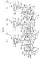
- the automatic brake system 150 shown in Fig. 9 and Fig. 10 is configured such that when the traveling pedal 110 is not stepped on (not operated) and the arm 122 is pivoted, a portion of the work oil fed to the arm cylinder 137 is forwarded to the main brake 62, so that this main brake 62 is actuated to brake the wheels 4, 5 (front and rear wheels 4, 5).
- the main brake 62 is used not only as the traveling brake for braking the wheels 4, 5 in response to a stepping operation on the brake pedal 100, but also as an automatic brake for braking the wheels 4, 5 in operative association with a pivotal movement of the arm 122 when the traveling pedal 110 is not operated and the arm 122 is pivoted.
- the traveling brake and the automatic brake may be provided separately from each other.
- the automatic brake is not limited to the hydraulically operated brake, but can be a mechanical operation type brake. Further, this need not be a disc brake, but can be a drum brake or any other type of brake.
- the automatic brake system 150 includes a first shuttle valve 151, a pressure reducing valve 162, a first switchover valve 153, a second switchover valve 154 and a second shuttle valve 155.
- the first switchover valve 153 can be switched over between a communicating position 153a for allowing communication of work oil from the pressure reducing valve 152 (arm cylinder 137 side) to the main brake 62 side when the traveling pedal 110 is not operated and a shutting position 153b for shutting off the communication of the work oil from the pressure reducing valve 152 (arm cylinder 137 side) to the main brake 62 side when the traveling pedal 110 is operated.
- the second switchover valve 154 is incorporated in a work oil communication passageway between the first switchover valve 153 and the pressure reducing valve 152 (arm cylinder 137 side) and can be switched over between a communicating position 154a for allowing communication of work oil from the pressure reducing valve 152 (arm cylinder 137 side) to the first switchover valve 153 when the arm 122 is pivoted and a shutting position 154b for shutting off the communication of the work oil from the pressure reducing valve 152 (arm cylinder 137 side) to the first switchover valve 153 when the arm 122 is not pivoted.
- the second shuttle valve 155 is capable of selectively feeding, to the main brake 62, either one (the one having the higher pressure) of the work oil fed from the master cylinder 111 (brake pedal 109 side) and the work oil fed from the first switchover valve 153 (arm cylinder 137 side) when the traveling pedal 110 is not operated and the arm 122 is pivoted at the same time.
- the first switchover valve 163 is comprised of an electromagnetic valve which is urged by a spring 156 to the direction to be switched over to the shutting position 153b and which also is switched over to the communicating position 153a in response to an electric signal (ON signal).
- a traveling sensor 157 comprised of e.g. a limit switch or the like which detects whether the traveling pedal 110 is being stepped on or not, is turned OFF (OFF signal is transmitted to the first switchover valve 153), whereby the first switchover valve 153 is demagnetized and this first switchover valve 153 is switched over to the shutting position 163b.
- the traveling sensor 157 is turned ON (ON signal is transmitted to the first switchover valve 153), whereby the first switchover valve 153 is magnetized and this first switchover valve 153 is switched over to the communicating position 153a.
- the second switchover valve 154 is an electromagnetic switchover valve which is urged by a spring 158 to the direction to be switched over to the shutting position 154b and which also is switched over to the communicating position 154a in response to an electric signal (ON signal).
- an arm sensor 159 comprised of e.g. a limit switch or the like which detects whether the arm operating lever 146 for operating the arm is being operated or not, is turned OFF, whereby the second switchover valve 154 is demagnetized and this second switchover valve 154 is switched over to the shutting position 164b.
- the arm sensor 159 is turned ON, whereby the second switchover valve 154 is magnetized and this second switchover valve 154 is switched over to the communicating position 154a.
- the automatic brake system 150 having the above-described construction, for instance, in case a scooping operation of earth/sand or the like is to be effected, from the working posture where the pivot 130 of the bucket 123 is located downwardly of the pivot 121 of the arm 122 and the bottom face of the bucket 123 is placed in opposition to the ground surface and the arm 122 has been pivoted to bring the bucket 123 closer to the machine body 1 as illustrated in Fig. 1 , the wheel loader 1 will be caused to travel forward to bring the leading end of the bucket 123 to the vicinity of or contact with the earth/sand or the like and then the forward traveling will be stopped.
- the stepping operation on the traveling pedal 110 will be released and at the same time, the scooping action of the bucket 123 will be effected with pivoting the arm 122 forwardly.
- the first switchover valve 153 and the second switchover valve 154 are switched over respectively to the communicating positions 153a, 154a, so that a portion of the work oil fed to the rod side of the arm cylinder 137 will be fed to the rear face side of the main brake piston 68 of the piston housing portion 69 of the main brake 63 via: the first shuttle valve 151 ⁇ pressure reducing valve 152 ⁇ communication oil passage 175 of second switchover valve 164 ⁇ communication oil passage 162 of the first switchover valve 163 ⁇ second shuttle valve 155, whereby the main brake 62 is actuated to brake the wheels 4, 5.
- the first switchover valve 153 is switched over to the shutting position 153b, so that the first switchover valve 153 shuts off the communication of the portion of the work oil fed to the arm cylinder 137 to the main brake 62 side and at the same time, the work oil present inside the piston housing portion 69 of the main brake 62 will be tank-drained via: second shuttle valve 155 ⁇ drain oil passage 160 of the first switchover valve 153 ⁇ drain circuit 161 from the first switchover valve 63 to work oil tank (oil pan) 60, whereby the braking of the wheels 4, 5 is released.
- the main brake 62 will not be activated. Further, if the pivotal movement of the arm 122 is stopped while the stepping on the traveling pedal 110 is released, as shown in Fig. 10 (c) , the second switchover valve 154 will be switched over to the shutting position 154b, the work oil present inside the piston housing portion 69 of the main brake 62 will be tank-drained via: second shuttle valve 155 ⁇ communication oil passage 162 ⁇ pipe passage 163 between the first switchover valve 63 and the second switchover valve 164 ⁇ drain oil passage 164 of the second switchover valve 164 ⁇ drain circuit 16 from the second switchover valve 154 to work oil tank (oil pan) 60, whereby the braking of the wheels 4, 5 is released.
- the drain oil passage 164 of the second switchover valve 154 and the drain circuit 165 together constitute a pressure relief circuit for relieving pressure in the pipe passage 163 extending between the first switchover valve 153 and the second switchover valve 154 when the traveling pedal 110 is being operated and the arm 122 is being not pivoted. Further, if the brake pedal 109 is stepped on while the traveling pedal 110 is not being stepped on, the work oil (brake oil) is fed from the master cylinder 111 via the second shuttle valve 155 to the main brake 62, whereby this main brake 62 is activated.
- the first switchover valve 153 when demagnetized, is switched over by a spring, to the communicating position 163a and switched over, when magnetized, to the shutting position 154b.
- the second switchover valve 154 may be incorporated within the wok oil flow passage extending between the first switchover valve 153 and the second shuttle valve 155.
- the first switchover valve 153 and/or second switchover valve 154 may be comprised of a pilot operation switchover valve operated by pilot work oil.
- the first switchover valve 153 in response to a stepping operation on the traveling pedal 110, the first switchover valve 153 will be switched over to the shutting position 153b by the pilot work oil from the traveling remote control valve 114.
- the traveling pedal 110 is not stepped on, the first switchover valve 153 will be switched over to the shutting position 153a by means of the spring.
- the second switchover valve 154 is comprised of a pilot operation switchover valve, in response to an operation on the operating lever 146 for arm operation, the second switchover valve 154 will be switched over to the communicating position 154a by the pilot work oil from the arm/swivel remote control valve 117. And, when the arm operating lever 146 is not operated, the second switchover valve 154 will be switched over to the shutting position 154b by means of the spring.
- the traveling pedal 110 is not operated and the arm 122 is pivoted, in association with the pivotal movement of the arm 122, a portion of the work oil fed to the arm cylinder 137 is fed to the brake 62 (automatic brake).
- the invention is not limited thereto.
- the work oil is fed to the main brake 62 from an appropriate portion of the feed circuit of the work oil discharged from the main pump 58
- the pilot work oil from the arm/swivel remote control valve 147 for controlling the arm control valve V4 to the arm/swivel remote control valve 147 may be used as a work oil for activating the main brake 62 when the arm 122 is pivoted while the traveling pedal 110 is not being operated.
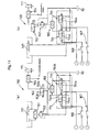
- An automatic brake system 150 shown in Fig. 11 (a) includes two of the above-described second switchover valves 154 comprised of electromagnetic valves in juxtaposition in the work oil communication passage extending from the speed reducing valve 152 (arm cylinder 137 side) to the first switchover valve 153 and includes also a third shuttle valve 166 for feeding the work oil past the second switchover valve 154 switched over to the communicating position 154a of the two second switchover valves 164, to the first switchover valve 153.
- the system differs from the above-described automatic brake system 150.
- the rest of the construction is substantially identical to the automatic brake system 150 shown in Fig. 9 .
- one second switchover valve 154 is configured as a second switchover valve 154 which is magnetized when the arm operating means is operated to pivot the arm 122 in one direction, to be switched over to the communicating position 154a.
- the other second switchover valve 154 is configured as a second switchover valve 154 which is magnetized when the arm operating means is operated to pivot the arm 122 in the other direction, to be switched over to the communicating position 154a.
- the arm operating means there is employed an operating means which includes an operating button for expanding the arm cylinder 137 and an operating button for contracting the arm cylinder 137, and the arm/swivel remote control valve 147 is operated by pressing operations on these operational buttons.
- One second switchover valve 154 is energized by a switch 167 which is turned ON In response to a pressing operation on one operational button.
- the other second switchover valve 154 is energized by a switch 168 which is turned ON in response to a pressing operation on the other operational button.
- the switches 167, 168 are turned OFF, whereby the second switchover valves 154 will be demagnetized.
- the arm control valve V4 may be comprised of an electromagnetic valve, so that the arm control valve V4 may be controlled by an electric signal generated by a pressing operation on the operational button.
- an automatic brake system 150 shown in Fig. 11 (b) differs from the automatic brake system 150 shown in Fig. 11 (a) in that this system omits the first shuttle valve 151 and includes a pressure reducing valve 152 in a work oil communication passage extending from the first switchover valve 153 and the third shuttle valve 166.
- the rest of the construction is substantially identical to the automatic brake system shown in Fig. 11 (a) .
- a detecting sensor such as a limit switch for detecting a pivot operation when the arm operating lever described above is pivoted in one direction and a detecting sensor such as a limit switch for detecting a pivot operation when the arm operating lever described above is pivoted in the other direction, so that in response to detection signal from one detecting sensor, one second switchover valve 154 is switched over and in response to detection signal from the other detecting sensor, the other second switchover valve 154 is switched over.
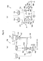
- An automatic brake system 150 shown in Fig. 12 (a) differs in that a pilot check valve is employed as the second switchover valve 154 included in the automatic brake system 150 shown in Fig.
- this pilot check valve is incorporated in the work oil communication passage extending between the first switchover valve 153 and the second shuttle valve 155, and there is provided a third shuttle valve 169 for sending, to the second switchover valve 154, the pilot work oil of the higher pressure side of the two lines of pilot work oil (one for the arm cylinder expansion and the other for the arm cylinder contraction) sent from the arm/swivel remote control valve 147 to the arm control valve V4.
- the rest of the construction is substantially identical to the automatic brake system 150 shown in Fig. 9 .
- the second switchover valve 154 is closed.
- the traveling pedal 110 is not stepped on and the arm 122 is pivoted, the first switchover valve 153 is magnetized to be switched over to the communicating position 153a and also the second switchover valve 154 is opened by the pilot work oil from the arm/swivel remote control valve 147, so that a portion of the work oil fed to the arm cylinder 137 is sent via the pressure reducing valve 152 to the first switchover valve 153 and flows past the first switchover valve 153 and the second switchover valve 154 and is sent via the second shuttle valve 155 to the main brake 62 to brake the wheels 4, 5.
- the automatic brake system 150 when the traveling pedal 110 is stepped when the arm 122 is not being pivoted, the work oil is tank-drained from the main brake 62: via: second shuttle valve 155 ⁇ second switchover valve 154 ⁇ drain oil passage 160 of the first switchover valve 153 ⁇ drain circuit 161, thus releasing the operation of the main brake 62.
- the automatic brake system 150 shown in Fig. 12 (b) differs from the automatic brake system shown in Fig. 12 (a) in that the second switchover valve 154 is incorporated in the work oil communication passageway between the pressure reducing valve 152 and the first switchover valve 153. The rest of the construction is substantially identical to the automatic brake system 150 shown in Fig. 12 (a) .
- a pilot operation switchover valve switched over by a pilot operation pressure and there is provided a third shuttle valve 180 for sending the high pressure side pilot work oil from the arm/swivel remote control valve 147 to the second switchover valve 154, so that the second switchover valve 154 is switched over to the communicating position 154a by the pilot work oil from the arm/swivel remote control valve 147.
- the rest of the construction is substantially identical to the automatic brake system 150 shown in Fig. 9 .
- An automatic brake system 150 shown in Fig. 13 (b) differs from the automatic brake system shown in Fig. 12 (b) in that a third switchover valve 171 is incorporated in the pilot oil passage 170 between the third shuttle valve 169 and the second switchover valve 154 of the automatic brake system 150 of Fig. 12 (b) and the first switchover valve 153 includes a first drain oil passage 194 for draining the work oil from the automatic brake to the drain circuit 161 in case the first switchover valve 153 is switched over during operation of the traveling pedal 110 and a second drain oil passage 195 for draining the pressure of the pipe passage 163 between the first switchover valve 153 and the second switchover valve 154 to the drain circuit 161 via the drain pipe passage 172.
- the rest of the construction is substantially identical to the automatic brake system 150 shown in Fig. 12 (b) .
- the third switchover valve 171 is comprised of an electromagnetic switchover valve, which is magnetized when the traveling pedal 110 is not stepped on, to be switched over to a communicating position 171a for allowing passage of the pilot work oil.
- the valve is demagnetized to be switched over by a spring 173 to a shutting position 171b for shutting off the communication of the pilot work oil 170.
- this automatic brake system 150 when the traveling pedal 110 is operated and the arm 122 is not pivoted, no trapped pressure will develop in the pipe passage 163 between the first switchover valve 153 and the second switchover valve 154.
- the first switchover valve 153 in the automatic brake system 150 shown in Fig. 12 (a) is comprised of a pilot operation switchover valve which is switched over to a shutting position 153b by the pilot work oil from the traveling remote control valve 114 when the traveling pedal 110 is stepped forwardly or rearwardly and there is provided a fourth shuttle valve 174 for sending the pilot operation oil from the traveling remote control valve 114 to the first switchover valve 153 when the traveling pedal 110 is stepped forwardly or rearwardly.
- the rest of the construction is substantially identical to the automatic brake system 150 shown in Fig. 12 (a) .
- a master cylinder 176 for feeding work oil to the automatic brake (this can be the above-described main brake 62 acting also as a traveling brake or a brake dedicated to the automatic brake system 150), an automatic brake cylinder 177, a traveling shuttle valve 178 for sending a portion (high pressure side) of the pilot work oil from the traveling remote control valve 114 to the bottom side of the automatic brake cylinder 177 when the traveling pedal 110 is stepped on forwardly or rearwardly, an arm shuttle valve 179 for sending a portion of the pilot work oil sent from the arm/swivel remote control valve 147 to the rod side of the automatic brake cylinder 177 when the arm operating lever 146 is pivoted to one side or the other side, and a transmission mechanism 180 for transmitting movement of a piston rod 177a of the automatic brake cylinder 177 to the master cylinder 176.
- a master cylinder 176 for feeding work oil to the automatic brake (this can be the above-described main brake 62 acting also as a traveling brake or a brake dedicated to the automatic brake system
- the transmission mechanism 180 includes a first arm 182 and a second arm 183 having base portions thereof fixed to a pivotable first pivotal portion 181, a third arm 185 and a fourth arm 186 having base portions thereof fixed to a pivotable second pivotal portion 183, a coupling link 187 for operably coupling the leading end side of the second arm 183 with the leading end side of the third arm 185, and a stopper 188 which comes into contact with a third link to restrict movement of the piston rod 177a of the automatic brake cylinder 177 in its projecting direction.
- the leading end side of the piston rod 177a of the automatic brake cylinder 177 is operably coupled to the leading end side of the first arm 182.
- a push rod 198 of the master cylinder 176 is operably coupled to the leading end side of the fourth arm 186.
- the piston rod 177a of the automatic brake cylinder 177 is retracted, the first arm 182 is pulled, so that the first, second arms 12 are pivoted, and also the third arm 185 is pulled by the coupling link 178, so that the third, fourth arms 122 are pivoted.
- the push rod 198 of the master cylinder 176 is pushed in by the fourth arm 186, thus pressing the piston inside this master cylinder 176.
- the work oil in the master cylinder 176 is sent to the automatic brake, whereby the automatic brake is activated to brake the wheels 4, 5.
- An automatic brake system 150 shown in Fig. 15 (a) includes a traveling switchover valve 191 incorporated in a work oil communication oil passageway extending from the main pump 58 to the bottom side of the automatic brake cylinder 177, a pilot check valve 192 disposed upstream of this traveling switchover valve 191, an arm shuttle valve 179 for sending, to the pilot check valve 192, a portion of the pilot work oil sent from the arm/swivel remote control valve 147 to the arm control valve V4 when the arm operating lever 146 is pivoted to one or the other side, and a transmission mechanism 180 for transmitting movement of the piston rod 177a of the automatic brake cylinder 177 to the master cylinder 176.
- the traveling switchover valve 191 is comprised of a switchover valve similar to the first switchover valve 153 described above.
- the pilot check valve 192 is comprised of a pilot check valve similar to the second switchover valve 154 described above.
- the transmission mechanism 180 differs from the above-described transmission mechanism 180 in that the stopper 188 provided in the latter is not provided and the direction of the fourth arm 186 is different, the rest of the construction being substantially identical to that of the above-described transmission mechanism.
- the pilot work oil from the arm/swivel remote control valve 147 is sent via the arm shuttle valve 179 to the pilot check valve 192, so that this pilot check valve 192 is opened and also the traveling switchover valve 191 is magnetized to be switched over to the communicating position 191a, so that the work oil from the main pump 58 is fed to the bottom side of the automatic brake cylinder 177.
- the traveling switchover valve 191 used in the latter is comprised now of a pilot operation switchover valve and there is provided a traveling shuttle valve 178 for sending a portion of the pilot work oil from the traveling remote control valve to the traveling switchover valve 191 when the traveling pedal 110 is stepped on forwardly or rearwardly.
- the rest of the construction is substantially identical to that of the automatic brake system 150 shown in Fig. 15 (b) .
- the present invention is applicable to a wheel loader having a machine body travelably supported on wheels and a work device mounted on the machine body.
Landscapes
- Engineering & Computer Science (AREA)
- General Engineering & Computer Science (AREA)
- Mining & Mineral Resources (AREA)
- Civil Engineering (AREA)
- Structural Engineering (AREA)
- Mechanical Engineering (AREA)
- Transportation (AREA)
- Operation Control Of Excavators (AREA)
Applications Claiming Priority (3)
| Application Number | Priority Date | Filing Date | Title |
|---|---|---|---|
| JP2006092024A JP4481265B2 (ja) | 2006-03-29 | 2006-03-29 | ホイールローダ |
| JP2006092023A JP4481264B2 (ja) | 2006-03-29 | 2006-03-29 | ホイールローダのオートブレーキ方法及びホイールローダ |
| PCT/JP2007/055345 WO2007111158A1 (ja) | 2006-03-29 | 2007-03-16 | ホイールローダ |
Publications (1)
| Publication Number | Publication Date |
|---|---|
| EP2000600A1 true EP2000600A1 (de) | 2008-12-10 |
Family
ID=38541078
Family Applications (1)
| Application Number | Title | Priority Date | Filing Date |
|---|---|---|---|
| EP07738790A Withdrawn EP2000600A1 (de) | 2006-03-29 | 2007-03-16 | Radlader |
Country Status (4)
| Country | Link |
|---|---|
| US (1) | US8276705B2 (de) |
| EP (1) | EP2000600A1 (de) |
| KR (1) | KR100998097B1 (de) |
| WO (1) | WO2007111158A1 (de) |
Families Citing this family (16)
| Publication number | Priority date | Publication date | Assignee | Title |
|---|---|---|---|---|
| CN101929171A (zh) * | 2010-07-26 | 2010-12-29 | 徐工集团工程机械股份有限公司江苏徐州工程机械研究院 | 轮式装载机的动臂定位方法及装置 |
| US8858151B2 (en) * | 2011-08-16 | 2014-10-14 | Caterpillar Inc. | Machine having hydraulically actuated implement system with down force control, and method |
| KR101778308B1 (ko) | 2011-12-27 | 2017-09-27 | 두산인프라코어 주식회사 | 건설중장비용 병렬 링키지 타입 작업장치 |
| JP5205536B1 (ja) * | 2012-06-28 | 2013-06-05 | 株式会社小松製作所 | ホイールローダ |
| US9181676B2 (en) * | 2013-01-11 | 2015-11-10 | Deere & Company | Machine foot control operational pattern and method thereof |
| US9453519B2 (en) * | 2013-07-05 | 2016-09-27 | Kanzaki Kokyukoki Mfg. Co., Ltd. | Transaxle |
| JP6398446B2 (ja) * | 2014-08-08 | 2018-10-03 | 井関農機株式会社 | トラクター |
| JP1522700S (de) * | 2014-09-05 | 2015-04-27 | ||
| JP1522701S (de) * | 2014-09-05 | 2015-04-27 | ||
| US9212038B1 (en) * | 2014-10-07 | 2015-12-15 | Kelly Presti | Automated portable personal lift |
| EP3239553B1 (de) * | 2014-12-25 | 2019-09-04 | Mitsubishi Logisnext Co., Ltd. | Achse für industriefahrzeug |
| US10641388B2 (en) | 2015-12-07 | 2020-05-05 | Kubota Corporation | Hydraulic system of work machine and work machine |
| CN110065497B (zh) * | 2019-05-24 | 2023-05-19 | 徐工集团工程机械股份有限公司科技分公司 | 一种高速装载机高低速自动切换控制系统 |
| US11623492B2 (en) * | 2020-11-04 | 2023-04-11 | Terex South Dakota, Inc. | Vehicle suspension system |
| US11623493B2 (en) * | 2020-11-04 | 2023-04-11 | Terex South Dakota, Inc. | Vehicle suspension system |
| CN113003501B (zh) * | 2021-03-19 | 2022-06-24 | 湖南星邦智能装备股份有限公司 | 高空作业平台的浮动装置 |
Family Cites Families (14)
| Publication number | Priority date | Publication date | Assignee | Title |
|---|---|---|---|---|
| US3688879A (en) * | 1970-07-07 | 1972-09-05 | Arnold A Buletti | Auxiliary brake system |
| US3973805A (en) * | 1971-09-20 | 1976-08-10 | Royal Industries, Inc. | Motor vehicle security system and security method |
| JPS5664041A (en) | 1979-10-31 | 1981-06-01 | Furukawa Mining Co Ltd | Wheel type loader |
| JPS6092914A (ja) | 1983-10-27 | 1985-05-24 | Nippon Denso Co Ltd | 車高制御装置 |
| JPS60261765A (ja) * | 1984-06-07 | 1985-12-25 | Honda Motor Co Ltd | 車両の制動装置 |
| JPS622472U (de) * | 1985-06-21 | 1987-01-09 | ||
| JPH0790883A (ja) * | 1991-09-02 | 1995-04-04 | Hitachi Constr Mach Co Ltd | ホイ−ルロ−ダの自動デフロック制御装置 |
| JPH0622472U (ja) | 1992-06-24 | 1994-03-25 | チュァン チン−パオ | 折り畳み式テント・フレーム |
| KR970040698A (ko) | 1995-12-29 | 1997-07-24 | 유상부 | 휠타입 굴삭기의 작업브레이크장치 |
| DE19616732B4 (de) * | 1996-04-26 | 2007-02-08 | Robert Bosch Gmbh | Verfahren und Vorrichtung zur Steuerung der Bremsanlage eines Fahrzeugs |
| JP2003106967A (ja) * | 2001-09-28 | 2003-04-09 | Shimadzu Corp | 油圧−サーボ式材料試験機 |
| US6631320B1 (en) * | 2002-11-27 | 2003-10-07 | Caterpillar Inc | Electronic traction control system |
| JP2005171608A (ja) | 2003-12-10 | 2005-06-30 | Kubota Corp | 作業機 |
| GB2439333A (en) * | 2006-06-20 | 2007-12-27 | Bamford Excavators Ltd | Loading machine with ABS |
-
2007
- 2007-03-16 US US12/282,493 patent/US8276705B2/en active Active
- 2007-03-16 WO PCT/JP2007/055345 patent/WO2007111158A1/ja not_active Ceased
- 2007-03-16 KR KR1020087022188A patent/KR100998097B1/ko not_active Expired - Fee Related
- 2007-03-16 EP EP07738790A patent/EP2000600A1/de not_active Withdrawn
Non-Patent Citations (1)
| Title |
|---|
| See references of WO2007111158A1 * |
Also Published As
| Publication number | Publication date |
|---|---|
| KR100998097B1 (ko) | 2010-12-02 |
| US8276705B2 (en) | 2012-10-02 |
| US20090252586A1 (en) | 2009-10-08 |
| WO2007111158A1 (ja) | 2007-10-04 |
| KR20080103555A (ko) | 2008-11-27 |
Similar Documents
| Publication | Publication Date | Title |
|---|---|---|
| US8276705B2 (en) | Wheel loader | |
| EP2134905B1 (de) | Hydraulikkraftverwaltungssystem | |
| JP3805632B2 (ja) | ブルドーザー及びピッチ制御システム | |
| EP2466017A1 (de) | Hydraulischer Antrieb mit geschlossenem Kreis mit Unterstützung einer Pumpe aus einem offenen Kreis für Hochgeschwindigkeitsfahrbewegungen | |
| JP7324654B2 (ja) | 建設機械の油圧システム | |
| WO2012107186A1 (en) | Hydrostatic system configured to be integrated in an excavator | |
| JPH08199620A (ja) | ブルドーザの土工板姿勢制御装置およびその制御方法 | |
| CN111287232A (zh) | 用于作业机械的改进的作业机具附接件 | |
| US20040182233A1 (en) | Hydraulic control apparatus for controlling hydraulic cylinder for implement | |
| US3978998A (en) | Fast hoist control system | |
| JPS5836132B2 (ja) | バツクホ−装着旋回ポスト作動用液圧系統 | |
| JP7210651B2 (ja) | 作業機の油圧システム | |
| CN101415889B (zh) | 轮式装载机 | |
| JP4606365B2 (ja) | ローダ | |
| AU720849B2 (en) | Multifunction valve stack | |
| US4015679A (en) | Drive range and lock control system | |
| JP4481265B2 (ja) | ホイールローダ | |
| US4126082A (en) | Travel-brake control system | |
| JP2009293631A (ja) | 作業機の油圧システム | |
| JP2019065996A (ja) | 作業機の油圧システム | |
| JP3386691B2 (ja) | 作業車輛の油圧回路 | |
| JP7005443B2 (ja) | 作業機の油圧システム | |
| WO2026050713A1 (en) | Hydraulic high flow manifold | |
| JP6656994B2 (ja) | 作業機の油圧システム | |
| JP2005065611A (ja) | 作業車両 |
Legal Events
| Date | Code | Title | Description |
|---|---|---|---|
| PUAI | Public reference made under article 153(3) epc to a published international application that has entered the european phase |
Free format text: ORIGINAL CODE: 0009012 |
|
| 17P | Request for examination filed |
Effective date: 20080908 |
|
| AK | Designated contracting states |
Kind code of ref document: A1 Designated state(s): AT BE BG CH LI |
|
| RBV | Designated contracting states (corrected) |
Designated state(s): DE FR GB IT |
|
| DAX | Request for extension of the european patent (deleted) | ||
| RBV | Designated contracting states (corrected) |
Designated state(s): DE FR GB IT |
|
| STAA | Information on the status of an ep patent application or granted ep patent |
Free format text: STATUS: THE APPLICATION HAS BEEN WITHDRAWN |
|
| 18W | Application withdrawn |
Effective date: 20130205 |