EP2000571B1 - Sewing machine and method for operating such a sewing machine - Google Patents
Sewing machine and method for operating such a sewing machine Download PDFInfo
- Publication number
- EP2000571B1 EP2000571B1 EP08009867.6A EP08009867A EP2000571B1 EP 2000571 B1 EP2000571 B1 EP 2000571B1 EP 08009867 A EP08009867 A EP 08009867A EP 2000571 B1 EP2000571 B1 EP 2000571B1
- Authority
- EP
- European Patent Office
- Prior art keywords
- feed
- adjustment
- sewing
- fabric
- feeder
- Prior art date
- Legal status (The legal status is an assumption and is not a legal conclusion. Google has not performed a legal analysis and makes no representation as to the accuracy of the status listed.)
- Active
Links
- 238000009958 sewing Methods 0.000 title claims description 91
- 238000000034 method Methods 0.000 title claims description 6
- 239000004744 fabric Substances 0.000 claims description 29
- 230000007246 mechanism Effects 0.000 claims description 2
- 230000001419 dependent effect Effects 0.000 claims 1
- 239000000463 material Substances 0.000 description 19
- 230000008859 change Effects 0.000 description 16
- 230000005540 biological transmission Effects 0.000 description 8
- 238000011017 operating method Methods 0.000 description 8
- 230000003287 optical effect Effects 0.000 description 4
- 230000002093 peripheral effect Effects 0.000 description 4
- 230000006978 adaptation Effects 0.000 description 2
- 238000006243 chemical reaction Methods 0.000 description 2
- 238000004891 communication Methods 0.000 description 2
- 238000006073 displacement reaction Methods 0.000 description 2
- 241001136792 Alle Species 0.000 description 1
- 230000004308 accommodation Effects 0.000 description 1
- 230000004888 barrier function Effects 0.000 description 1
- 230000015572 biosynthetic process Effects 0.000 description 1
- 238000012937 correction Methods 0.000 description 1
- 230000008878 coupling Effects 0.000 description 1
- 238000010168 coupling process Methods 0.000 description 1
- 238000005859 coupling reaction Methods 0.000 description 1
- 238000002788 crimping Methods 0.000 description 1
- 230000009347 mechanical transmission Effects 0.000 description 1
- 239000002994 raw material Substances 0.000 description 1
- 238000004904 shortening Methods 0.000 description 1
- 230000001360 synchronised effect Effects 0.000 description 1
- 238000012546 transfer Methods 0.000 description 1
Images


Classifications
-
- D—TEXTILES; PAPER
- D05—SEWING; EMBROIDERING; TUFTING
- D05B—SEWING
- D05B27/00—Work-feeding means
- D05B27/02—Work-feeding means with feed dogs having horizontal and vertical movements
- D05B27/04—Work-feeding means with feed dogs having horizontal and vertical movements arranged above the workpieces
-
- D—TEXTILES; PAPER
- D05—SEWING; EMBROIDERING; TUFTING
- D05B—SEWING
- D05B27/00—Work-feeding means
-
- D—TEXTILES; PAPER
- D05—SEWING; EMBROIDERING; TUFTING
- D05B—SEWING
- D05B35/00—Work-feeding or -handling elements not otherwise provided for
-
- D—TEXTILES; PAPER
- D05—SEWING; EMBROIDERING; TUFTING
- D05B—SEWING
- D05B69/00—Driving-gear; Control devices
- D05B69/20—Control devices responsive to the number of stitches made
Definitions
- the invention relates to a sewing machine with a transport device for the intermittent feed of sewing material according to the preamble of claim 1. Furthermore, the invention relates to various operating methods for such a sewing machine.
- a sewing machine of the type mentioned is known from the EP 0 512 145 B1 , There, a stitch length adjustment is described by corresponding change of feed values of an upper and a lower conveyor.
- From the US 4,867,082 is a sewing machine with an upper feed dog and two lower conveyors known.
- a transport feed of the upper transporter can be adjusted via an adjusting device with an actuator and a guided holder.
- Feed lengths of the two lower conveyors can be adjusted via corresponding actuators.
- the actuators for the upper feed dog and the lower feeders each have an adjustment motor.
- the actuators of the upper conveyor and the lower conveyors are in signal communication with a controller to which a memory belongs. Stored setting data are used to control the actuators of the upper conveyor and the lower conveyors during the execution of a sewing sequence.
- the control device can be in signal communication with external sensors and / or enable direct influencing of the adjusting drives by operating elements of the sewing machine, for example foot switches, toggle levers or pushbuttons.
- the control device can be in signal communication with external sensors and / or enable direct influencing of the adjusting drives by operating elements of the sewing machine, for example foot switches, toggle levers or pushbuttons.
- such a feed length adjustment can take place over an entire sewing sequence, wherein in each case the corresponding setting data for the adjusting drives are called up.
- an adjustment of the feed Changing sewing material parameters, for example a changing composition of the fabric or a change in the sewing direction relative to the angle of the warp and weft threads of the sewing material, are possible.
- a different ratio of the feed lengths between the upper and the lower feed dog can also be specified, which is also referred to below as the Raff feed value.
- the change in the feed length can also be used to achieve desired optical effects during sewing.
- the mechanical top feed adjusting device and the mechanical bottom feed adjusting device are designed as link adjustments and have at least one adjusting device adjustable along the adjusting link.
- Such gate adjustments as adjusting devices have proven themselves because of their mechanical robustness.
- At least one of the adjusting devices has a rotatably driven via the associated adjustment cam plate having a peripheral surface with varying radius in peripheral sections, with the peripheral surface of an adjusting body sections to Vorschubinver ein cooperates, which is mechanically coupled to the associated feed dog.
- Such adjustment can be structurally integrated into a sewing machine with little effort.
- a stepper motor according to claim 3 allows a finely predetermined feed adjustment.
- An accommodation of the adjusting drive according to claim 4 leads to a compact sewing machine.
- An embodiment according to claim 5 enables an automatic adjustment of the thread tension, in particular to a predetermined length of the control device stitch length.
- Another object of the invention is to provide operating methods for the sewing machine according to the invention.
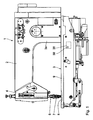
- a sewing machine 1 has an arm 2, a base plate 3, and a stand 3a connecting them.
- the free end of the arm 2 carries a head 4.
- an arm shaft 5 is mounted, which is rotatably driven by a main drive not shown in detail.
- needle bar 6 is vertically moved up and down.
- a needle 7 is mounted at the lower end of the needle bar 6.
- the needle 7 passes through a stitch hole in a throat plate 8, which is inserted into a support plate 9 of the base plate 3.
- Below the needle plate 8 a co-operating with the needle 7 for looping gripper is arranged, which is driven by a gripper shaft and a deflection gear, which are not shown in detail.
- the drive of the gripper is also derived from the arm shaft 5.
- a fabric presser 11 which is mounted at the lower end of a Stoffdrückerstange 12.
- a transport device 14 For intermittent feed of the material in a sewing direction 13, with an arrow in the Fig. 12 is shown and in the Fig. 12 extends from right to left, serves a transport device 14, whose frictionally cooperating with the material conveyors increased in the Fig. 12 are shown. With an upper surface of the fabric acts an upper Transporter 15 together, in the Fig. 12 on the one hand shown in a zero position and on the other hand at 15 'in one of these opposite to the left displaced maximum stroke position.
- the two lower conveyors 16, 17 have along the sewing direction 13 spaced-apart contact portions for frictional feed contact with the fabric underside.
- the transporters 16, 17 are shown on the one hand in a zero position and on the other hand at 16 ', 17' in a relation to this left displaced maximum stroke position.
- the transporters 15 to 17 each have a sawtooth profiling 18a.
- the stroke of all three transporters 15 to 17 in the sewing direction can be set individually for each of the transporters 15 to 17 controlled. This will be described below in connection with the feed length of one of the lower transporters 16, 17 on the basis of Fig. 7 to 11 explained.
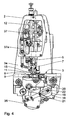
- a first stepper motor 18 which is fixedly mounted on the base plate 3.
- the first stepper motor 18 is operatively connected to the first lower feed dog 16.
- a contact body 19 Connected to a drive shaft of the first stepping motor 18 in a rotationally fixed manner is a contact body 19 with a spiral-shaped outer peripheral abutment wall 20.
- the abutment wall 20 thus has a radius varying in circumferential sections.
- the contact body 19 is a driven rotatable cam.
- the abutment wall 20 abuts an adjusting or counter body in the form of a needle bearing 21, which is held in a fork-shaped deflecting rod 22.
- the needle bearing 21 thus represents a sliding body for cooperation with the abutment wall 20.
- the deflection bar 22 is connected via a hinge 23 with a link adjusting body 24, which in turn is rotatably connected to a slotted guide 25. Along the latter is a sliding block 26 displaced. This is in turn connected to a triangular lever 27. About an eccentric shaft 28 of the triangle lever 27 is vibrated. Depending on the guide direction of the slotted guide 25, this vibration is implemented in a more or less large torsional vibration of a transmission shaft 29 about its longitudinal axis.
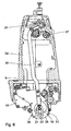
- FIG. 7 and FIGS. 10 and 11 show a lower feed adjusting device 30, to which the first stepping motor 18 belongs, in a "small lift" position in which practically no angular displacement is transmitted to the transmission shaft 29 during operation.
- the assigned lower transporter When operating the sewing machine, the assigned lower transporter remains virtually in its zero position. In the "small stroke” position, the outermost end of the abutment wall 20 bears against the needle bearing 21, so that the latter is maximally spaced from the drive shaft of the first stepping motor 18.
- the 8 and 9 In contrast, show the position "long stroke" of the first lower feed adjustment 30. In this position “large stroke” the abutment wall 20 is at its innermost end on the needle bearing 21, so that the distance between this and the drive shaft of the stepping motor 18 is low. Between the two positions “small stroke” and “large stroke” is a relative rotation of the drive shaft of the first Stepping motor 18 of about 225 °. Since the stepper motor 18 has a high step resolution, all intermediate positions between the positions "small stroke” and "large stroke” can be practically infinitely preset.
- a second lower transport adjustment device 31 is used for controlled specification of the feed length of the second lower conveyor 17.
- the second lower transport adjustment device 31 has a second stepper motor 32, which is also mounted on the base plate 3 under the support plate 9.
- the second stepper motor 32 is operatively connected to the second lower feed dog 17.
- the mechanical actuation of the second lower feed adjusting device 31 corresponds to that of the first lower feed adjusting device 30 and has the same structure as this, with the difference that the second Untes transport adjustment device 31 on a transmission shaft 33 acts, which runs in the executed as a hollow shaft transmission shaft 29 of the first lower feed adjustment device 30 and is rotated independently of this about a common longitudinal axis of the two shafts 29, 33 by a predetermined angular amount to the feed control.
- the transmission shafts 29, 33 act independently of one another on each of the lower conveyors 16 and 17.
- the feed length of the lower feed conveyor controlled by the second lower feed adjusting device 31 can be preset via the rotation of the second stepping motor 32, as described above in connection with FIG the first lower feed adjusting device 30 has been explained.
- the Fig. 5 shows the second lower feed adjusting device 31 in a position similar to that of the first lower feed adjusting device 30 after the 10 and 11 corresponds, ie in the position "small stroke".
- the second lower feed adjusting device 31 can be practically continuously changed to the "long stroke" position.
- an upper transport adjustment 34 To adjust a feed length of the upper conveyor 15 is an upper transport adjustment 34.
- This has a third stepper motor 35, which is also mounted on the base plate 3 and mounted under the support plate 9.
- the third stepping motor 35 is in operative connection with the upper conveyor 15.
- the mechanical transmission from the stepping motor 35 to the upper feed dog 15 corresponds to that which has been explained above with reference to the two lower feed adjusting devices 30, 31.
- the upper transport adjusting device 34 has as a transfer member between the needle roller bearing 21 and the guide adjusting body 24 a pull rod 36, which extends in the stator 3a.
- a corresponding angular displacement is imparted to a transmission shaft 37 of the top feed adjusting device 34, which in turn is mechanically connected to the upper feed dog 15 via a push rod 37a.
- the transmission shaft 37 runs along the arm 2.
- the three stepper motors 18, 32, 35 are all housed within a housing surrounding the base plate 3 and not shown in the drawing of the sewing machine.
- control device 38 is connected to the two lower feed adjustment devices 30, 31 and the upper transport adjustment device 34 in signal connection.
- the control device 38 has a memory device 39, in which data to be processed sewing sequences and this sewing sequence data associated adjustment data for controlling the stepper motors 18, 32, 35 are stored during the execution of the sewing sequence.
- a first feed value for advancing the material to be sewn by the transporters 15 to 17 is initially predetermined by corresponding synchronous control of all three stepper motors 18, 32, 35, controlled by the control device 38. Subsequently, the sewing material, as long as this first default value is set, so with a first stitch length, sewn. Subsequently, a second, from the first different feed value to the material feed with the transporters 15 to 17 by concurrently driving the stepper motors 18, 32, 35 predetermined. Subsequently, the sewing material is sewn with the resulting second feed value, which may for example be greater than the first feed value, so that the subsequent seam has a greater stitch length than before.
- This controlled conversion of the feed value can be done, for example, depending on detected signal values of additional sensors on the sewing machine 1, for example a light barrier sensor or a touch sensor, which detects when one end of the material is reached and therefore only a few stitches are to be sewed to the seam end, so that it is ensured by appropriate adjustment of the stitch length that the last stitch ends at a predetermined location, without this last stitch in its length being too different from the previous stitches. Such a difference is undesirable for optical reasons. Even when sewing corner stitching this can be a stitch shortening can be prevented in the corner.
- the thread tension is automatically adjusted, controlled by the control device 38.
- the control device 38 controls an electronic thread tension transmitter of the sewing machine 1.
- the thread tension is increased in particular as the stitch length is increased.
- a first Raff feed value for advancing the material to be conveyed with the transporters 15 to 17, wherein the upper conveyor 15 z. B. makes a material feed, which is different from the Nähgutvorschub the lower conveyors 16, 17. Subsequently, the fabric is sewn with this first Raff feed value. Subsequently, by appropriate adjustment of either the stepping motor 35 for the upper conveyor 15 or concurrent adjustment of the stepper motors 18, 32 for the two lower conveyors 16, 17, a second, predetermined by the first Raff feed value.
- the differential is utilized.
- This is first a first crimp feed value for advancing the material to be sewn with the two lower transporters 16, 17, wherein z. B. the first lower feed dog 16 performs a Nähgutvorschub different from the Nähgutvorschub the second lower conveyor 17.
- the feed supplied by the second lower feed dog 17 is slightly larger than that supplied by the first lower feed dog 16. The fabric is now sewn with this first crimp feed value.
- a second crimp feed value is predetermined, which differs from the first crimp feed value.
- the conversion can for example be such that the difference in the feed between the two lower conveyors 16, 17 is now greater than before, so that the lower work piece is now crimped by the two lower conveyors 16, 17 more.
- the fabric is sewn with the second crimp feed value.
- This third method of operation can also be used to achieve certain optical results when sewing or to compensate for a change in the properties of the material during sewing, in particular when sewing seams with changes in direction.
- Changes in sewing material parameters are, for example, changes in the type of binding of the sewing material, changes in the raw material composition of the sewing material or changes in the degree of twist of the warp and weft threads with each other.
- the control of the stepper motors 18, 32, 35 can automatically by the controller 38 when executing a sewing program or a Sewing sequence done.
- this control directly, for example via a foot switch or a toggle or a button by the operator.
- the operator can therefore change the stitch length, the differentiability or the differential as needed during sewing.
- Such a direct control is possible in particular for making quick corrections, which is often desirable, for example, when sewing in sleeves.
- blank tolerances can be compensated.
- this can also be done depending on internal parameters, for example the number of sewn stitches or the sewn seam length.
Landscapes
- Engineering & Computer Science (AREA)
- Textile Engineering (AREA)
- Mechanical Engineering (AREA)
- Sewing Machines And Sewing (AREA)
Description
Die Erfindung betrifft eine Nähmaschine mit einer Transporteinrichtung zum intermittierenden Vorschub von Nähgut nach dem Oberbegriff des Anspruchs 1. Ferner betrifft die Erfindung verschiedene Betriebsverfahren für eine derartige Nähmaschine.The invention relates to a sewing machine with a transport device for the intermittent feed of sewing material according to the preamble of claim 1. Furthermore, the invention relates to various operating methods for such a sewing machine.
Eine Nähmaschine der eingangs genannten Art ist bekannt aus der
Aus der
Aus der
Viele, insbesondere anspruchsvolle Nähaufgaben erfordern eine flexiblere Anpassung des Nähgutvorschubs an die jeweiligen Nähbedingungen, als dies durch die bekannten Nähmaschinen gewährleistet werden kann.Many, especially demanding sewing tasks require a more flexible adaptation of the Nähgutvorschubs to the respective sewing conditions, as can be ensured by the known sewing machines.
Es ist daher eine Aufgabe der vorliegenden Erfindung, eine Nähmaschine der eingangs genannten Art derart weiterzubilden, dass die Flexibilität des Nähgutvorschubs zur Anpassung an unterschiedliche Nähanforderungen erhöht ist.It is therefore an object of the present invention, a sewing machine of the type mentioned in such a way that the flexibility of the Nähgutvorschubs is increased to adapt to different sewing requirements.
Diese Aufgabe ist erfindungsgemäß gelöst durch eine Nähmaschine mit den im Anspruch 1 angegebenen Merkmalen.This object is achieved by a sewing machine with the features specified in claim 1.
Erfindungsgemäß wurde erkannt, dass es möglich ist, die an sich bereits bekannte Mechanik zur Veränderung der Vorschublänge eines unteren und eines oberen Transporteurs durch den Einsatz entsprechender Verstellantriebe zu automatisieren. Die Vorschublängenänderung kann nun durch Ansteuerung des entsprechenden Verstellantriebs über die Steuereinrichtung erfolgen. Die Steuereinrichtung kann mit externen Sensoren in Signalverbindung stehen und/oder eine direkte Beeinflussung der Verstellantriebe durch Bedienelemente der Nähmaschine, zum Beispiel Fußschalter, Kniehebel oder Taster ermöglichen. Auf diese Weise ist eine flexible Anpassung des Nähgutvorschubs beispielsweise an den Verlauf einer Naht, möglich. Zum Beispiel kann die Stichlänge im Eckbereich zwischen zwei aneinander über Eck anstoßenden Nähten so angepasst werden, dass der Stich in der Ecke endet, ohne dass der letzte Stich sich in seiner Länge von vorhergehenden Stichen zu unterscheiden braucht. Über die Steuereinrichtung kann eine derartige Vorschublängen-Anpassung über eine gesamte Nähsequenz erfolgen, wobei jeweils die entsprechenden Einstelldaten für die Verstellantriebe abgerufen werden. Auch eine Anpassung des Vorschubs an sich ändernde Nähgutparameter, zum Beispiel an eine sich ändernde Stoffzusammensetzung oder an eine Änderung der Nährichtung zum Winkel der Kett- und Schussfäden des Nähguts, ist möglich. Neben einer automatischen Vorgabe verschiedener Gesamt-Vorschublängen, also verschiedener Stichlängen, lässt sich auch ein unterschiedliches Verhältnis der Vorschublängen zwischen dem oberen und dem unteren Transporteur vorgeben, was nachfolgend auch als Raff-Vorschubwert bezeichnet wird. Die Änderung der Vorschublänge kann auch zur Erzielung erwünschter optischer Effekte beim Nähen eingesetzt werden. Die mechanische Obertransport-Verstelleinrichtung und die mechanische Untertransport-Verstelleinrichtung sind als Kulissenverstellungen ausgeführt und weisen mindestens einen längs der Verstelleinrichtung verstellbaren Kulissen-Einstellkörper auf. Derartige Kulissenverstellungen als Verstelleinrichtungen haben sich aufgrund ihrer mechanischen Robustheit bewährt. Mindestens eine der Verstelleinrichtungen hat eine über den zugeordneten Verstellantrieb angetrieben drehbare Kurvenscheibe mit einer Umfangsfläche mit in Umfangsabschnitten variierendem Radius, wobei mit der Umfangsfläche ein Verstellkörper abschnittsweise zu Vorschublängenverstellung zusammenwirkt, der mechanisch mit dem zugeordneten Transporteur gekoppelt ist. Eine derartige Verstelleinrichtung lässt sich mit geringem Aufwand baulich in eine Nähmaschine integrieren.According to the invention it has been recognized that it is possible to automate the already known mechanism for changing the feed length of a lower and an upper conveyor by the use of appropriate adjustment drives. The feed length change can now take place by controlling the corresponding adjustment drive via the control device. The control device can be in signal communication with external sensors and / or enable direct influencing of the adjusting drives by operating elements of the sewing machine, for example foot switches, toggle levers or pushbuttons. In this way, a flexible adaptation of the Nähgutvorschubs, for example, to the course of a seam, possible. For example, the stitch length in the corner between two abutting seams can be adjusted so that the stitch ends in the corner without the last stitch needing to be different in length from previous stitches. By means of the control device, such a feed length adjustment can take place over an entire sewing sequence, wherein in each case the corresponding setting data for the adjusting drives are called up. Also an adjustment of the feed Changing sewing material parameters, for example a changing composition of the fabric or a change in the sewing direction relative to the angle of the warp and weft threads of the sewing material, are possible. In addition to an automatic specification of different total feed lengths, ie different stitch lengths, a different ratio of the feed lengths between the upper and the lower feed dog can also be specified, which is also referred to below as the Raff feed value. The change in the feed length can also be used to achieve desired optical effects during sewing. The mechanical top feed adjusting device and the mechanical bottom feed adjusting device are designed as link adjustments and have at least one adjusting device adjustable along the adjusting link. Such gate adjustments as adjusting devices have proven themselves because of their mechanical robustness. At least one of the adjusting devices has a rotatably driven via the associated adjustment cam plate having a peripheral surface with varying radius in peripheral sections, with the peripheral surface of an adjusting body sections to Vorschublängeverstellung cooperates, which is mechanically coupled to the associated feed dog. Such adjustment can be structurally integrated into a sewing machine with little effort.
Bei einer Nähmaschine nach Anspruch 2 lässt sich nicht nur die Länge oder das Verhältnis der Vorschublänge des oberen Transporteurs zur Vorschublänge des unteren Transporteurs einstellen, sondern es lassen sich auch die Vorschublängen der beiden unteren Transporteure untereinander einstellen. Dies wird nachfolgend auch als Vorgabe unterschiedlicher Kräusel-Vorschubwerte bezeichnet. Durch die zusätzliche und über die Steuereinrichtung ansteuerbare Untertransport-Verstelleinrichtung lässt sich die Flexibilität bei der Vorgabe von Vorschubmöglichkeiten durch die erfindungsgemäße Nähmaschine weiter erhöhen.In a sewing machine according to
Ein Schrittmotor nach Anspruch 3 ermöglicht eine fein vorgebbare Vorschub-Verstellung.A stepper motor according to
Eine Unterbringung des Verstellantriebs nach Anspruch 4 führt zu einer kompakten Nähmaschine.An accommodation of the adjusting drive according to
Eine Ausgestaltung nach Anspruch 5 ermöglicht eine automatische Anpassung der Fadenspannung insbesondere an eine über die Steuereinrichtung vorgegebene Stichlänge.An embodiment according to
Eine weitere Aufgabe der Erfindung ist es, Betriebsverfahren für die erfindungsgemäße Nähmaschine anzugeben.Another object of the invention is to provide operating methods for the sewing machine according to the invention.
Diese Aufgabe ist erfindungsgemäß gelöst durch die Betriebsverfahren nach den Ansprüche 6 und 7 und, was die Nähmaschine nach Anspruch 2 angeht, durch ein Betriebsverfahren nach Anspruch 8.This object is achieved by the operating method according to
Die Vorteile dieser Betriebsverfahren entsprechen denen, die vorstehend schon unter Bezugnahme auf die erfindungsgemäße Nähmaschine erläutert wurden.The advantages of these operating methods correspond to those which have already been explained above with reference to the sewing machine according to the invention.
Ein Ausführungsbeispiel der Erfindung wird nachfolgend anhand der Zeichnung näher erläutert. In dieser zeigen:
- Fig. 1
- eine Seitenansicht einer Nähmaschine mit einer Grundplatte;
- Fig. 2
- eine Aufsicht auf die Nähmaschine nach
Fig. 1 ; - Fig. 3
- eine Unteransicht der Nähmaschine nach
Fig. 1 ; - Fig. 4
- eine stirnseitige Ansicht der Nähmaschine gemäß Blickrichtung IV in
Fig. 3 ; - Fig. 5
- einen Schnitt gemäß Linie V-V in
Fig. 3 ; - Fig. 6
- einen Schnitt gemäß Linie VI-VI in
Fig. 2 ; - Fig. 7
- einen Schnitt gemäß Linie VII-VII in
Fig. 3 ; - Fig. 8
- eine Seitenansicht der Grundplatte aus der gleichen Blickrichtung wie
Fig. 1 , wobei im Vergleich zurFig. 1 mechanische Komponenten fehlen, sodass die mechanische Kopplung einer mechanischen Untertransport-Verstelleinrichtung verbleibt, wobei diese Untertransport-Verstelleinrichtung in der Stellung "großer Hub" vorliegt; - Fig. 9
- einen Schnitt gemäß Linie IX-IX in
Fig. 8 ; - Fig. 10
- eine zu
Fig. 8 ähnliche Ansicht mit der Untertransport-Verstelleinrichtung in der Stellung "kleiner Hub", - Fig. 11
- einen Schnitt gemäß Linie XI-XI in
Fig. 10 ; und - Fig. 12
- vergrößert einen Ausschnitt aus
Fig. 4 , wobei insbesondere die Transporteure zum Nähgutvorschub dargestellt sind.
- Fig. 1
- a side view of a sewing machine with a base plate;
- Fig. 2
- a top view of the sewing machine
Fig. 1 ; - Fig. 3
- a bottom view of the sewing machine after
Fig. 1 ; - Fig. 4
- an end view of the sewing machine according to viewing direction IV in
Fig. 3 ; - Fig. 5
- a section along line VV in
Fig. 3 ; - Fig. 6
- a section according to line VI-VI in
Fig. 2 ; - Fig. 7
- a section according to line VII-VII in
Fig. 3 ; - Fig. 8
- a side view of the base plate from the same direction as
Fig. 1 , in comparison toFig. 1 mechanical components are missing, leaving the mechanical coupling of a mechanical bottom feed adjusting device, this bottom feed adjusting device being in the "high lift"position; - Fig. 9
- a section along line IX-IX in
Fig. 8 ; - Fig. 10
- one too
Fig. 8 similar view with the bottom feed adjusting device in the "small stroke" position, - Fig. 11
- a section along line XI-XI in
Fig. 10 ; and - Fig. 12
- enlarges a section
Fig. 4 , wherein in particular the conveyors are shown for Nähgutvorschub.
Eine Nähmaschine 1 hat einen Arm 2, eine Grundplatte 3 und einen diese verbindenden Ständer 3a. Das freie Ende des Arms 2 trägt einen Kopf 4. Im Arm 2 ist eine Armwelle 5 gelagert, die von einem nicht im Einzelnen dargestellten Hauptantrieb drehantreibbar ist. Über die Armwelle 5 ist eine im Kopf 4 gelagerte Nadelstange 6 vertikal auf- und abbewegbar. Am unteren Ende der Nadelstange 6 ist eine Nadel 7 montiert. Beim Betrieb der Nähmaschine 1 durchtritt die Nadel 7 ein Stichloch in einer Stichplatte 8, die in eine Auflageplatte 9 der Grundplatte 3 eingesetzt ist. Unterhalb der Stichplatte 8 ist ein zur Schlingenbildung mit der Nadel 7 zusammenwirkender Greifer angeordnet, der über eine Greiferwelle und ein Umlenkgetriebe, die nicht näher dargestellt sind, angetrieben ist. Der Antrieb des Greifers wird ebenfalls von der Armwelle 5 abgeleitet. Zur Fixierung des Nähguts bei der Stichbildung dient ein Stoffdrücker 11, der am unteren Ende einer Stoffdrückerstange 12 montiert ist.A sewing machine 1 has an
Zum intermittierenden Vorschub des Nähguts in einer Nährichtung 13, die mit einem Pfeil in der
Mit einer Unterseite des Nähguts kommen zwei untere Transporteure, nämlich ein erster unterer Transporteur 16 und ein zweiter unterer Transporteur 17 in Kontakt. Der erste untere Transporteur 16 ist in der
Zum intermittierend reibschlüssigen Vorschub-Kontakt mit dem Nähgut weisen die Transporteure 15 bis 17 jeweils eine Sägezahnprofilierung 18a auf.For intermittently frictional feed contact with the sewing material, the
Der Hub aller drei Transporteure 15 bis 17 in der Nährichtung kann individuell für jeden der Transporteure 15 bis 17 gesteuert vorgegeben werden. Dies wird nachfolgend in Zusammenhang mit der Vorschublänge eines der unteren Transporteure 16, 17 anhand der
Zur Einstellung der Vorschublänge dient ein erster Schrittmotor 18, der fest an der Grundplatte 3 montiert ist. Der erste Schrittmotor 18 steht mit dem ersten unteren Transporteur 16 in Wirkverbindung. Mit einer Antriebswelle des ersten Schrittmotors 18 drehfest verbunden ist ein Anlagekörper 19 mit einer spiralförmigen äußeren Umfangs-Anlagewand 20. Die Anlagewand 20 hat also einen in Umfangsabschnitten variierenden Radius. Der Anlagekörper 19 stellt eine angetrieben drehbare Kurvenscheibe dar. Die Anlagewand 20 liegt an einem Verstell- bzw. Gegenkörper in Form eines Nadellagers 21 an, das in einer gabelförmigen Umlenkstange 22 gehalten ist. Das Nadellager 21 stellt also einen Gleitkörper zum Zusammenwirken mit der Anlagewand 20 dar. Die Umlenkstange 22 ist über ein Gelenk 23 mit einem Kulissen-Einstellkörper 24 verbunden, der seinerseits drehfest mit einer Kulissenführung 25 verbunden ist. Längs letzterer ist ein Kulissenstein 26 verschiebbar. Dieser ist wiederum mit einem Dreieckshebel 27 verbunden. Über eine Exzenterwelle 28 wird der Dreieckshebel 27 in Schwingung versetzt. Je nach der Führungsrichtung der Kulissenführung 25 wird diese Schwingung in einer mehr oder minder große Drehschwingung einer Übertragungswelle 29 um deren Längsachse umgesetzt.To adjust the feed length is a
Die
Die
In der Stellung "großer Hub" wird der Kulissenstein 26 in der Kulissenführung 25 in einer in der
In Zwischenstellungen der ersten Untertransport-Verstelleinrichtung 30 zwischen den dargestellten Stellungen "kleiner Hub" und "großer Hub" wird entsprechend der erste untere Transporteur 16 zwischen seiner Nullstellung und einer zwischen der Nullstellung und der Stellung "großer Hub" gelegenen Stellung verlagert. Zwischen dem in der
Eine zweite Untertransport-Verstelleinrichtung 31 dient zur gesteuerten Vorgabe der Vorschublänge des zweiten unteren Transporteurs 17. Die zweite Untertransport-Verstelleinrichtung 31 hat einen zweiten Schrittmotor 32, der ebenfalls an der Grundplatte 3 unter der Auflageplatte 9 montiert ist. Der zweite Schrittmotor 32 steht mit dem zweiten unteren Transporteur 17 in Wirkverbindung. Die mechanische Ansteuerung der zweiten Untertransport-Verstelleinrichtung 31 entspricht derjenigen der ersten Untertransport-Verstelleinrichtung 30 und ist genauso aufgebaut wie diese mit dem Unterschied, dass die zweite Untemansport-Verstelleinrichtung 31 auf eine Übertragungswelle 33 wirkt, die in der als Hohlwelle ausgeführten Übertragungswelle 29 der ersten Untertransport-Verstelleinrichtung 30 läuft und unabhängig von dieser um eine gemeinsame Längsachse der beiden Wellen 29, 33 um einem vorgegebenen Winkelbetrag zur Vorschubsteuerung verdreht wird.A second lower
Die Übertragungswellen 29, 33 wirken unabhängig voneinander jeweils auf einen der unteren Transporteure 16 und 17. Dabei lässt sich über die Verdrehung des zweiten Schrittmotors 32 die Vorschublänge des von der zweiten Untertransport-Verstelleinrichtung 31 angesteuerten unteren Transporteurs eingestellt vorgeben, wie dies vorstehend im Zusammenhang mit der ersten Untertransport-Verstelleinrichtung 30 erläutert wurde.The
Die
Zur Verstellung einer Vorschublänge des oberen Transporteurs 15 dient eine Obertransport-Verstelleinrichtung 34. Diese hat einen dritten Schrittmotor 35, der ebenfalls an der Grundplatte 3 angebracht und unter der Auflageplatte 9 montiert ist. Der dritte Schrittmotor 35 steht mit dem oberen Transporteur 15 in Wirkverbindung. Die mechanische Übertragung vom Schrittmotor 35 auf den oberen Transporteur 15 entspricht derjenigen, die vorstehend unter Bezugnahme auf die beiden Untertransport-Verstelleinrichtungen 30, 31 erläutet wurde. Im Unterschied zu den Untertransport-Verstelleinrichtungen 30, 31 hat die Obertransporterstelleinrichtung 34 als Übertragungsglied zwischen dem Nadellager 21 und dem Kulissen-Einstellkörper 24 eine Zugstange 36, die im Ständer 3a verläuft. Je nach der Drehstellung des dritten Schrittmotors 35 wird eine entsprechende Winkelverstellung an eine Übertragungswelle 37 der Obertransport-Verstelleinrichtung 34 vermittelt, die wiederum mechanisch über eine Schubstange 37a mit dem oberen Transporteur 15 verbunden ist. Die Übertragungswelle 37 läuft längs des Arms 2.To adjust a feed length of the
Die drei Schrittmotoren 18, 32, 35 sind sämtlich innerhalb eines die Grundplatte 3 umgebenden und in der Zeichnung nicht dargestellten Gehäuses der Nähmaschine untergebracht.The three
Eine in der
Aufgrund der unabhängigen Verstellmöglichkeiten der Vorschublängen der Transporteure 15 bis 17 über die Verstelleinrichtungen 30, 31 und 34 lassen sich Verstellmöglichkeiten realisieren, zu denen folgende Haupt-Verstellmöglichkeiten gehören:
- Zum einen lassen sich die Vorschublängen aller drei Transporteure 15
bis 17 synchron zueinander jeweils in gleicher Weise verstellen, sodass alle drei Transporteure 15bis 17 von einer ersten gemeinsamen Vorschublänge hin zu einer zweiten gemeinsamen Vorschublänge verstellt werden. In diesem Fall wird also der gesamte Transport-Vorschub der Nähmaschine 1 und damit die Stichlänge verändert.
- On the one hand, the feed lengths of all three
transporters 15 to 17 can be adjusted in synchronism with each other in the same way, so that all threetransporters 15 to 17 are adjusted from a first common feed length to a second common feed length. In this case, therefore, the entire transport feed of the sewing machine 1 and thus the stitch length is changed.
Zum zweiten ist es möglich, den Vorschub der beiden unteren Transporteure 16, 17 synchron zueinander zu verstellen, wobei die Vorschublänge des oberen Transporteurs entweder konstant bleibt oder um einen von der Veränderung der Vorschublänge der unteren Transporteure 16, 17 unterschiedlichen Betrag geändert wird. Durch eine solche Verstellung wird also der Unterschied zwischen den bei einem Transporthub realisierten Transportwegen einerseits der unteren Transporteure 16, 17 und andererseits des oberen Transporteurs 15 geändert. Dies wird nachfolgend als Differenzierbarkeit des Transports der Nähmaschine 1 bezeichnet oder als Änderung des Raff-Vorschubwertes. Durch diese Differenzierbarkeit kann eine Änderung der Raffung eines oberen Nähgutteils, welches vom oberen Transporteur 15 transportiert wird, relativ zu einem unteren Nähgutteil, welches von den unteren Transporteuren 16, 17 transportiert wird, erreicht werden.Secondly, it is possible to adjust the feed of the two
Zum dritten ist es möglich, lediglich die Vorschublängen der beiden unteren Transporteure 16, 17 relativ zueinander zu verstellen. Dadurch kann eine Veränderung einer durch die unteren Transporteure 16, 17 herbeigeführten Kräuselung eines unteren Nähgutteils beim Transport variiert werden. Diese verstellbare Eigenschaft des Nähguttransports durch die Nähmaschine 1 wird nachfolgend als Differential oder als Änderung des Kräusel-Vorschubwertes bezeichnet.Third, it is possible to adjust only the feed lengths of the two
Auch beliebige Überlagerungen dieser drei prinzipiellen Verstellmöglichkeiten "Änderung der Vorschublänge", "Differenzierbarkeit" und "Differential" sind möglich.Any overlays of these three basic adjustment options "change the feed length", "differentiability" and "differential" are possible.
Bei einem ersten beispielhaften Betriebsverfahren der Nähmaschine 1 wird zunächst durch entsprechende gleichlaufende Ansteuerung aller drei Schrittmotoren 18, 32, 35, gesteuert über die Steuereinrichtung 38, ein erster Vorschubwert zum Vorschub des Nähguts mit den Transporteuren 15 bis 17 vorgegeben. Anschließend wird das Nähgut, solange dieser erste Vorgabewert eingestellt ist, also mit einer ersten Stichlänge, genäht. Anschließend wird ein zweiter, vom ersten verschiedener Vorschubwert zum Nähgutvorschub mit den Transporteuren 15 bis 17 durch gleichlaufendes Ansteuern der Schrittmotoren 18, 32, 35 vorgegeben. Nachfolgend wird das Nähgut mit dem resultierenden zweiten Vorschubwert, der zum Beispiel größer sein kann als der erste Vorschubwert, genäht, sodass die nachfolgende Naht eine größere Stichlänge aufweist als zuvor.In a first exemplary operating method of the sewing machine 1, a first feed value for advancing the material to be sewn by the
Diese angesteuerte Umstellung des Vorschubwertes kann beispielsweise abhängig von erfassten Signalwerten zusätzlicher Sensoren an der Nähmaschine 1 erfolgen, zum Beispiel eines Lichtschrankensensors oder eines Tastsensors, der erfasst, wenn ein Ende des Nähguts erreicht ist und daher nur noch wenige Stiche bis zum Nahtende zu nähen sind, sodass durch entsprechende Anpassung der Stichlänge sichergestellt ist, dass der letzte Stich an einem vorgegebenen Ort endet, ohne dass dieser letzte Stich in seiner Länge sich von den vorhergehenden Stichen zu sehr unterscheidet. Ein derartiger Unterschied ist aus optischen Gründen unerwünscht. Auch beim Nähen von Ecknähen kann hierdurch eine Stichverkürzung im Eckbereich verhindert werden.This controlled conversion of the feed value can be done, for example, depending on detected signal values of additional sensors on the sewing machine 1, for example a light barrier sensor or a touch sensor, which detects when one end of the material is reached and therefore only a few stitches are to be sewed to the seam end, so that it is ensured by appropriate adjustment of the stitch length that the last stitch ends at a predetermined location, without this last stitch in its length being too different from the previous stitches. Such a difference is undesirable for optical reasons. Even when sewing corner stitching this can be a stitch shortening can be prevented in the corner.
Je nach vorgegebener Stichlänge wird, angesteuert über die Steuereinrichtung 38, auch die Fadenspannung automatisch angepasst. Hierzu steuert die Steuereinrichtung 38 einen elektronischen Fadenspannungs-Geber der Nähmaschine 1 an. Dabei wird bei Vergrößerung der Stichlänge die Fadenspannung insbesondere erhöht.Depending on the specified stitch length, the thread tension is automatically adjusted, controlled by the
Bei einem weiteren, alternativ oder zusätzlich einsetzbaren Betriebsverfahren für die Nähmaschine 1 wird die Differenzierbarkeit ausgenutzt. Hierbei wird zunächst ein erster Raff-Vorschubwert zum Vorschub des Nähguts mit den Transporteuren 15 bis 17 vorgegeben, wobei der obere Transporteur 15 z. B. einen Nähgutvorschub leistet, der vom Nähgutvorschub der unteren Transporteure 16, 17 verschieden ist. Anschließend wird das Nähgut mit diesem ersten Raff-Vorschubwert genäht. Anschließend wird, durch entsprechende Verstellung entweder des Schrittmotors 35 für den oberen Transporteur 15 oder gleichlaufendes Verstellen der Schrittmotoren 18, 32 für die beiden unteren Transporteure 16, 17 ein zweiter, vom ersten verschiedener Raff-Vorschubwert vorgegeben. Dies kann beispielsweise so geschehen, dass beim zweiten Raff-Vorschubwert der Unterschied im Vorschub zwischen dem oberen Transporteur 15 und den beiden unteren Transporteuren 16, 17 größer ist als vorher. Nun wird beim nachfolgenden Nähen der Stoff stärker gerafft als vorher. Dies kann beispielsweise zum Erzielen gewünschter optischer Ergebnisse beim Nähen eingesetzt werden oder aber eine Änderung im Raffverhalten des Stoffs, beispielsweise beim Nähen von Nähten mit Richtungsänderung bei Stoffen mit Reibungs-Vorzugsrichtungen, erwünscht kompensieren.In a further, alternatively or additionally usable operating method for the sewing machine 1, the differentiability is utilized. Here, first, a first Raff feed value for advancing the material to be conveyed with the
Bei einem weiteren Betriebsverfahren, welches alternativ oder zusätzlich zum vorstehend genannten Betriebsverfahren bei der Nähmaschine 1 durchgeführt werden kann, wird das Differential ausgenutzt. Hierbei wird zunächst ein erster Kräusel-Vorschubwert zum Vorschub des Nähgutes mit den beiden unteren Transporteuren 16, 17 vorgegeben, wobei z. B. der erste untere Transporteur 16 einen Nähgutvorschub leistet, der vom Nähgutvorschub des zweiten unteren Transporteurs 17 verschieden ist. Insbesondere ist beim ersten Kräusel-Vorschubwert der Vorschub, den der zweite untere Transporteur 17 liefert, etwas größer als der, den der erste untere Transporteur 16 liefert. Das Nähgut wird nun mit diesem ersten Kräusel-Vorschubwert genäht. Anschließend wird durch entsprechendes Ansteuern zum Beispiel eines der beiden Schrittmotoren 18, 32 für die unteren Transporteure 16, 17 ein zweiter Kräusel-Vorschubwert vorgegeben, der sich vom ersten Kräusel-Vorschubwert unterscheidet. Die Umstellung kann beispielsweise so sein, dass der Unterschied im Vorschub zwischen den beiden unteren Transporteuren 16, 17 nun größer ist als vorher, sodass das untere Nähgutteil nun durch die beiden unteren Transporteure 16, 17 stärker gekräuselt wird. Anschließend wird das Nähgut mit dem zweiten Kräusel-Vorschubwert genäht. Auch dieses dritte Betriebsverfahren kann zum Erzielen bestimmter optischer Ergebnisse beim Nähen oder zum Ausgleich einer Änderung der Stoffeigenschaften während des Nähens, insbesondere beim Nähen von Nähten mit Richtungsänderung, genutzt werden.In a further method of operation, which can be performed alternatively or in addition to the above-mentioned operating method in the sewing machine 1, the differential is utilized. This is first a first crimp feed value for advancing the material to be sewn with the two
Änderungen von Nähgut-Parametern, denen durch Änderung der Differenzierbarkeit oder des Differentials Rechnung getragen werden kann, sind beispielsweise Änderungen in der Bindungsart des Nähguts, Änderungen in der Rohstoffzusammensetzung des Nähguts oder Änderungen im Zwirnungsgrad der Kett- und Schussfäden untereinander.Changes in sewing material parameters, which can be accommodated by changing the differentiability or the differential, are, for example, changes in the type of binding of the sewing material, changes in the raw material composition of the sewing material or changes in the degree of twist of the warp and weft threads with each other.
Die Ansteuerung der Schrittmotoren 18, 32, 35 kann automatisch durch die Steuereinrichtung 38 beim Abarbeiten eines Nähprogramms oder einer Nähsequenz erfolgen. Alternativ oder zusätzlich ist es möglich, diese Ansteuerung direkt, zum Beispiel über einen Fußschalter oder einen Kniehebel oder einen Taster von der Bedienperson zu ermöglichen. Die Bedienperson kann daher während des Nähens die Stichlänge, die Differenzierbarkeit oder das Differential nach Bedarf verändern. Eine derartige direkte Ansteuerung ist insbesondere zur Vornahme schneller Korrekturen möglich, was beispielsweise beim Ärmeleinnähen oft erwünscht ist. Hier lassen sich beispielsweise Zuschnitts-Toleranzen ausgleichen.The control of the
Insbesondere lassen sich Änderungen im Nähverhalten aufgrund einer Änderung des Winkels der Nährichtung zwischen der Kett- und Schussfadenrichtung des Nähguts kompensieren. Eine derartige Kompensation kann beispielsweise beim Nähen von gebogenen Nähten stufenlos angepasst erfolgen.In particular, changes in the sewing behavior due to a change in the angle of the sewing direction between the warp and weft direction of the fabric can be compensated. Such compensation can for example be made steplessly adapted when sewing bent seams.
Alternativ zu einer Ansteuerung der Vorschubänderung über externe Sensoren kann dies auch abhängig von internen Parametern, zum Beispiel der Anzahl der genähten Stiche oder der genähten Nahtstrecke, erfolgen.As an alternative to triggering the feed change via external sensors, this can also be done depending on internal parameters, for example the number of sewn stitches or the sewn seam length.
Claims (8)
- Sewing machine (1) comprising- a feed unit (14) for intermittent feeding of fabric, comprising-- at least one upper feeder (15) providing an intermittent frictional feed contact with an upper side of the fabric;-- at least one lower feeder (16, 17) providing an intermittent frictional feed contact with an underside of the fabric;- a mechanical upper feed adjustment device (34) for adjusting a feed length of the at least one upper feeder (15);- a mechanical lower feed adjustment device (30, 31) for adjusting a feed length of the at least one lower feeder (16, 17);- an upper feed adjustment drive (35) for adjusting the upper feed adjustment device (34);- a lower feed adjustment drive (18, 32) for adjusting the lower feed adjustment device (30, 31);a control device (38) which is in signal connection with the lower feed adjustment drive (18, 32) and the upper feed adjustment drive (35) and has a storage device (39) in which data are stored regarding sewing sequences to be executed as well as adjustment data which are assigned to these sewing sequence data for independently actuating the adjustment drives (18, 32, 35) when the sewing sequence is executed,- the adjustment devices (30, 31, 34) are guided slider mechanisms having at least one guided-slider adjustment body (24) that is displaceable along an adjustment direction (18, 32, 35) of the respective adjustment drive,- at least one of the adjustment devices (30, 31, 34) has a cam disk (19) that is drivable for rotation by the assigned adjustment drive (18, 32, 35), the cam disk (19) having a circumferential area (20) the radius of which varies over circumferential portions, wherein an adjustment body (21) interacts with sections of the circumferential area (20) for adjusting the feed length, the adjustment body (21) being mechanically coupled to the assigned feeder (15 to 17).
- Sewing machine according to claim 1, characterized in that the feed unit (14) additionally comprises:- at least an additional lower feeder (17, 16) providing an intermittent frictional feed contact with the underside of the fabric;- wherein the two lower feeders (16, 17) have contact portions along a sewing direction (13), the contact portions being disposed at a distance from one another for providing a feed contact with the underside of the fabric;- an additional mechanical lower feed adjustment device (31, 30) for adjusting a feed length of the additional lower feeder (17, 16);- an additional lower feed adjustment drive (35, 32) for adjusting the additional lower feed adjustment device (31, 30);- wherein the control device (38) is also in signal connection with the additional lower feed adjustment device (31, 30); and- wherein additional adjustment data are stored in the storage device (39), these additional adjustment data being assigned to the data regarding sewing sequences to be executed, for actuating the additional lower feed adjustment drive (35, 32) when the sewing sequence is executed.
- Sewing machine according to one of claims 1 to 2, characterized by a stepper motor (18, 32, 35) as adjustment drive.
- Sewing machine according to one of claims 1 to 3, characterized in that the at least one adjustment drive (18, 32, 35) is housed in a housing of the sewing machine (1).
- Sewing machine according to one of claims 1 to 4, characterized in that the control device (38) is connected to a thread tensioning device.
- Method of operation of a sewing machine according to one of claims 1 to 5 comprising the following steps:- setting a first feed value for moving the fabric by means of the at least one upper feeder (15) and the at least one lower feeder (16, 17);- sewing the fabric with the first feed value;- setting a second feed value for moving the fabric by means of the at least one upper feeder (15) and the at least one lower feeder (16, 17), the second feed value being different from the first feed value;- sewing the fabric with the second feed value.
- Method of operation of a sewing machine according to one of claims 1 to 5 comprising the following steps:- setting a first gathering feed value for moving the fabric by means of the at least one upper feeder (15) and the at least one lower feeder (16, 17), wherein the first gathering feed value is the ratio between the feed lengths of the upper feeder (15) and the lower feeder (16, 17);- sewing the fabric with the first gathering feed value;- setting a second gathering feed value for moving the fabric by means of the at least one upper feeder (15) and the at least one lower feeder (16, 17), the second gathering feed value being different from the first gathering feed value;- sewing the fabric with the second gathering feed value.
- Method of operation of a sewing machine according to claim 2 or according to one of claims 3 to 5 when at least dependent from claim 2, comprising the following steps:- setting a first ruffling feed value for moving the fabric by means of the two lower feeders (16, 17), wherein the ruffling feed value is the ratio between the feed lengths of the one lower feeder (16) and the other lower feeder (17);- sewing the fabric with the first ruffling feed value;- setting a second ruffling feed value for moving the fabric by means of the two lower feeders (16, 17), the second ruffling feed value being different from the first ruffling feed value;- sewing the fabric with the second ruffling feed value.
Applications Claiming Priority (1)
| Application Number | Priority Date | Filing Date | Title |
|---|---|---|---|
| DE102007026651A DE102007026651A1 (en) | 2007-06-08 | 2007-06-08 | Sewing machine and operating method for such a sewing machine |
Publications (3)
| Publication Number | Publication Date |
|---|---|
| EP2000571A2 EP2000571A2 (en) | 2008-12-10 |
| EP2000571A3 EP2000571A3 (en) | 2011-06-22 |
| EP2000571B1 true EP2000571B1 (en) | 2013-11-06 |
Family
ID=39811628
Family Applications (1)
| Application Number | Title | Priority Date | Filing Date |
|---|---|---|---|
| EP08009867.6A Active EP2000571B1 (en) | 2007-06-08 | 2008-05-30 | Sewing machine and method for operating such a sewing machine |
Country Status (5)
| Country | Link |
|---|---|
| EP (1) | EP2000571B1 (en) |
| JP (2) | JP2008302222A (en) |
| KR (2) | KR20080108035A (en) |
| CN (1) | CN101319436B (en) |
| DE (1) | DE102007026651A1 (en) |
Cited By (1)
| Publication number | Priority date | Publication date | Assignee | Title |
|---|---|---|---|---|
| TWI596250B (en) * | 2015-06-02 | 2017-08-21 | Zeng Hsing Industrial Co Ltd | Sewing machine feed feed compensation method |
Families Citing this family (9)
| Publication number | Priority date | Publication date | Assignee | Title |
|---|---|---|---|---|
| DE102008030797A1 (en) * | 2008-06-28 | 2009-12-31 | Dürkopp Adler AG | Sewing machine and method for operating such a sewing machine |
| JP5522981B2 (en) * | 2009-06-18 | 2014-06-18 | 日本発條株式会社 | Lower feed mechanism of sewing device and sewing device |
| DE102011052521B4 (en) | 2011-08-09 | 2023-02-23 | Chee Siang Industrial Co., Ltd. | pillar sewing machine |
| CN105734841B (en) * | 2014-12-08 | 2018-04-10 | 曾贤长 | The cloth conveying teeth differential attachment of sewing machine |
| CH712437A1 (en) | 2016-05-06 | 2017-11-15 | Bernina Int Ag | Sewing machine comprising a device for manually changing a transporter. |
| CN105803692A (en) * | 2016-05-22 | 2016-07-27 | 贵州大学 | Control device for sewing cloth cutting device |
| DE102017206499B3 (en) * | 2017-04-18 | 2018-05-03 | Dürkopp Adler AG | sewing machine |
| DE102017216725A1 (en) * | 2017-09-21 | 2019-03-21 | Dürkopp Adler AG | Method for operating a sewing machine and sewing machine for carrying out the method |
| CN110552120B (en) * | 2019-09-10 | 2022-03-25 | 杰克科技股份有限公司 | Automatic needle pitch adjusting structure of flat seaming machine |
Family Cites Families (13)
| Publication number | Priority date | Publication date | Assignee | Title |
|---|---|---|---|---|
| JPS56163689A (en) * | 1980-05-22 | 1981-12-16 | Mitsubishi Electric Corp | Sewing machine. feeding thereof can be adjusted |
| DE3216993C2 (en) * | 1982-05-06 | 1989-03-16 | Pfaff Industriemaschinen Gmbh, 6750 Kaiserslautern | Sewing machine with a device for producing shaped seams |
| IL78944A (en) * | 1985-06-03 | 1990-04-29 | Prouvost Sa | Method and sewing machine for automatically providing end of stitching at a given distance from the edge of a piece of fabric |
| DE3627470A1 (en) * | 1986-08-13 | 1988-02-18 | Pfaff Ind Masch | METHOD FOR SEWING THE CORNER OF A DOUBLE SEAM WITH A TWO NEEDLE SEWING MACHINE |
| IT1217796B (en) * | 1988-06-07 | 1990-03-30 | Rockwell Rimoldi Spa | ELECTRONIC DEVICE FOR THE MANAGEMENT OF AUTOSETTING IN INDUSTRIAL SEWING MACHINES. |
| DE59100858D1 (en) | 1991-05-10 | 1994-02-24 | Duerkopp Adler Ag | Process for producing a seam that changes direction in the course of the seam. |
| JPH0759970A (en) * | 1993-08-25 | 1995-03-07 | Brother Ind Ltd | Differential feed sewing machine |
| DE19920350C1 (en) * | 1999-05-04 | 2000-11-30 | Duerkopp Adler Ag | Method for operating a sewing machine for connecting a first sewing material part to a second sewing material part while incorporating fullness |
| JP3867012B2 (en) * | 2002-05-14 | 2007-01-10 | Juki株式会社 | Sewing machine cloth feeder |
| JP4509491B2 (en) * | 2003-04-21 | 2010-07-21 | Juki株式会社 | Differential feed sewing machine |
| JP4608998B2 (en) * | 2004-08-23 | 2011-01-12 | ブラザー工業株式会社 | Pattern sewing machine and cloth feeding method thereof |
| JP4364115B2 (en) * | 2004-12-03 | 2009-11-11 | Juki株式会社 | sewing machine |
| JP2006263177A (en) * | 2005-03-24 | 2006-10-05 | Juki Corp | Sewing machine |
-
2007
- 2007-06-08 DE DE102007026651A patent/DE102007026651A1/en not_active Withdrawn
-
2008
- 2008-05-30 EP EP08009867.6A patent/EP2000571B1/en active Active
- 2008-06-03 JP JP2008145743A patent/JP2008302222A/en active Pending
- 2008-06-05 KR KR1020080053002A patent/KR20080108035A/en not_active Application Discontinuation
- 2008-06-10 CN CN2008101101184A patent/CN101319436B/en active Active
-
2012
- 2012-12-14 JP JP2012007570U patent/JP3181916U/en not_active Expired - Fee Related
-
2014
- 2014-03-25 KR KR2020140002336U patent/KR200475371Y1/en not_active IP Right Cessation
Cited By (1)
| Publication number | Priority date | Publication date | Assignee | Title |
|---|---|---|---|---|
| TWI596250B (en) * | 2015-06-02 | 2017-08-21 | Zeng Hsing Industrial Co Ltd | Sewing machine feed feed compensation method |
Also Published As
| Publication number | Publication date |
|---|---|
| JP3181916U (en) | 2013-02-28 |
| DE102007026651A1 (en) | 2008-12-18 |
| KR20080108035A (en) | 2008-12-11 |
| EP2000571A3 (en) | 2011-06-22 |
| CN101319436B (en) | 2013-04-24 |
| KR200475371Y1 (en) | 2014-11-26 |
| KR20140002775U (en) | 2014-05-09 |
| JP2008302222A (en) | 2008-12-18 |
| EP2000571A2 (en) | 2008-12-10 |
| CN101319436A (en) | 2008-12-10 |
Similar Documents
| Publication | Publication Date | Title |
|---|---|---|
| EP2000571B1 (en) | Sewing machine and method for operating such a sewing machine | |
| DE102007031072B4 (en) | sewing machine | |
| DE102008051626B4 (en) | Material feed device of a sewing machine | |
| DE102017107281A1 (en) | sewing machine | |
| EP2138620B1 (en) | Sewing machine and method for operating same | |
| DE3216993A1 (en) | SEWING MACHINE WITH A DEVICE FOR MAKING MOLD SEAMS | |
| DE4230163A1 (en) | METHOD AND DEVICE FOR CONTROLLING THE EDGE POSITION OF A TEXTILE PIECE | |
| DE102006057581A1 (en) | sewing machine | |
| DE8533380U1 (en) | Sewing machine with differential feed | |
| DE102009004217A1 (en) | Two-needle sewing machine | |
| DE10321266B4 (en) | Nähgutzuführvorrichtung | |
| DE10002456B4 (en) | Fabric feed device for sewing machine | |
| DE10262180B4 (en) | yarn tensioner | |
| DE19624260A1 (en) | sewing machine | |
| DE19611793B4 (en) | Thread cutter for a chain stitch sewing machine | |
| DE2317975C3 (en) | Fabric feed for sewing machines | |
| DE202009000251U1 (en) | sewing machine | |
| EP2182102B1 (en) | Sewing machine | |
| DE69717261T2 (en) | ADJUSTABLE PRESSURE FOOT DEVICE FOR A MATTRESS SEWING MACHINE | |
| DE8316282U1 (en) | Feed drive for a stitch group sewing machine | |
| DE10125068C2 (en) | Sewing machine with a device for controlling a seam end point | |
| DE4207414C2 (en) | Flat knitting machine | |
| DE10025822A1 (en) | Device for transporting sewing material | |
| DE3721331C2 (en) | ||
| EP0376016B1 (en) | Sewing machine band feed guide |
Legal Events
| Date | Code | Title | Description |
|---|---|---|---|
| PUAI | Public reference made under article 153(3) epc to a published international application that has entered the european phase |
Free format text: ORIGINAL CODE: 0009012 |
|
| AK | Designated contracting states |
Kind code of ref document: A2 Designated state(s): AT BE BG CH CY CZ DE DK EE ES FI FR GB GR HR HU IE IS IT LI LT LU LV MC MT NL NO PL PT RO SE SI SK TR |
|
| AX | Request for extension of the european patent |
Extension state: AL BA MK RS |
|
| PUAL | Search report despatched |
Free format text: ORIGINAL CODE: 0009013 |
|
| AK | Designated contracting states |
Kind code of ref document: A3 Designated state(s): AT BE BG CH CY CZ DE DK EE ES FI FR GB GR HR HU IE IS IT LI LT LU LV MC MT NL NO PL PT RO SE SI SK TR |
|
| AX | Request for extension of the european patent |
Extension state: AL BA MK RS |
|
| RIC1 | Information provided on ipc code assigned before grant |
Ipc: D05B 27/00 20060101AFI20081016BHEP Ipc: D05B 69/20 20060101ALI20110516BHEP Ipc: D05B 69/00 20060101ALI20110516BHEP |
|
| 17P | Request for examination filed |
Effective date: 20111001 |
|
| 17Q | First examination report despatched |
Effective date: 20111216 |
|
| AKX | Designation fees paid |
Designated state(s): CZ DE RO |
|
| GRAP | Despatch of communication of intention to grant a patent |
Free format text: ORIGINAL CODE: EPIDOSNIGR1 |
|
| INTG | Intention to grant announced |
Effective date: 20130719 |
|
| GRAS | Grant fee paid |
Free format text: ORIGINAL CODE: EPIDOSNIGR3 |
|
| GRAA | (expected) grant |
Free format text: ORIGINAL CODE: 0009210 |
|
| AK | Designated contracting states |
Kind code of ref document: B1 Designated state(s): CZ DE RO |
|
| REG | Reference to a national code |
Ref country code: DE Ref legal event code: R096 Ref document number: 502008010887 Country of ref document: DE Effective date: 20140102 |
|
| REG | Reference to a national code |
Ref country code: RO Ref legal event code: EPE |
|
| REG | Reference to a national code |
Ref country code: DE Ref legal event code: R097 Ref document number: 502008010887 Country of ref document: DE |
|
| PLBE | No opposition filed within time limit |
Free format text: ORIGINAL CODE: 0009261 |
|
| STAA | Information on the status of an ep patent application or granted ep patent |
Free format text: STATUS: NO OPPOSITION FILED WITHIN TIME LIMIT |
|
| 26N | No opposition filed |
Effective date: 20140807 |
|
| REG | Reference to a national code |
Ref country code: DE Ref legal event code: R097 Ref document number: 502008010887 Country of ref document: DE Effective date: 20140807 |
|
| P01 | Opt-out of the competence of the unified patent court (upc) registered |
Effective date: 20230510 |
|
| PGFP | Annual fee paid to national office [announced via postgrant information from national office to epo] |
Ref country code: DE Payment date: 20230725 Year of fee payment: 16 |
|
| PGFP | Annual fee paid to national office [announced via postgrant information from national office to epo] |
Ref country code: CZ Payment date: 20240517 Year of fee payment: 17 |
|
| PGFP | Annual fee paid to national office [announced via postgrant information from national office to epo] |
Ref country code: RO Payment date: 20240523 Year of fee payment: 17 |