EP2000334B1 - Tampon coulissant - Google Patents
Tampon coulissant Download PDFInfo
- Publication number
- EP2000334B1 EP2000334B1 EP20070109756 EP07109756A EP2000334B1 EP 2000334 B1 EP2000334 B1 EP 2000334B1 EP 20070109756 EP20070109756 EP 20070109756 EP 07109756 A EP07109756 A EP 07109756A EP 2000334 B1 EP2000334 B1 EP 2000334B1
- Authority
- EP
- European Patent Office
- Prior art keywords
- slide pad
- thickness
- tyre
- bead
- rim
- Prior art date
- Legal status (The legal status is an assumption and is not a legal conclusion. Google has not performed a legal analysis and makes no representation as to the accuracy of the status listed.)
- Active
Links
Images


Classifications
-
- B—PERFORMING OPERATIONS; TRANSPORTING
- B60—VEHICLES IN GENERAL
- B60C—VEHICLE TYRES; TYRE INFLATION; TYRE CHANGING; CONNECTING VALVES TO INFLATABLE ELASTIC BODIES IN GENERAL; DEVICES OR ARRANGEMENTS RELATED TO TYRES
- B60C25/00—Apparatus or tools adapted for mounting, removing or inspecting tyres
- B60C25/01—Apparatus or tools adapted for mounting, removing or inspecting tyres for removing tyres from or mounting tyres on wheels
- B60C25/02—Tyre levers or the like, e.g. hand-held
- B60C25/04—Tyre levers or the like, e.g. hand-held pivotal about the wheel axis, or movable along the rim edge, e.g. rollable
Definitions
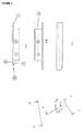
- This invention relates to a slide pad (1) for aligning a tyre on a rim and a method for using this slide pad (1).
- a constant gap is necessary for minimizing side force variations from the tyre under rolling conditions. Less variations in the side force results in a better performance under less vibrations of the wheel and the car.
- US 5 339 880 describes an apparatus for fitting bead portions of the tyre onto a wheel substantially uniformly and at the same time for filling inner pressure into the tyre.
- the object of the present invention is to give a simple mean for adjusting a tyre on a rim (14) with fewer variations in the side forces of the tyre under rolling conditions than known from the prior art.
- the device according to this inventions should give reproducible results without the need of a skilled operator.
- the duration of an alignment process using the device according to this invention should be shorter than those of the prior art.
- a slide pad (1) for aligning a constant distance between the rim edge wall (2) and the back side (3) of the bead part (4) of a tyre (5), wherein the slide pad (1) has a length of at least 50 mm, a height between 1 and 15 mm and a thickness between 2 and 9 mm, wherein one of the surface of the slide pad (1) being defined by the length and the thickness of the slide pad defines the lower side (6), the other rear (opposed) surface of the slide pad (1) being defined by the length and the thickness of the slide pad defines the upper side (7), one of the surface of the slide pad (1) being defined by the height and the thickness of the slide pad (1) defines the insertion front (8), the other rear (opposed) surface of the slide pad (1) being defined by the height and the thickness of the slide pad (1) defines the insertion end (9), and wherein the upper side (7) of the insertion front (8) of the slide pad (1) has a smaller thickness than the lower side (6) of the insertion front.
- This slide pad (1) has the major advantage that it is a simple device for adjusting the bead part (4) of a tyre precisely on a rim without moving the bead part (4) over the hump of the rim (14).
- the use of this slide pad (1) more effectively leads to a constant gap between the bead part (4) and the outer wall of the rim (14).
- This resulting matching of the bead structure is the key knowledge to provide an optimized way to the market providing an optimal tyre setup, especially in the formula one and for sports cars, reducing vibrations resulting from an incorrect adjustment of the bead part (4) on the tyre (5).
- the improvement when using the slide pad (1) according to the invention is a higher precision tyre mount work in a shorter time compared with the tools and principles of the prior art.
- the thickness of the slide pad (1) is important and increases from the insertion-edge- part to the end of the tip-part. This structure avoids the instability of positioning due to the return of bead part (4) caused by elasticity of rubber.
- a preferred embodiment of the slide pad according to the invention has a length between 110 and 150 mm.
- the slide pad (1) could have a height between 2 and 5 mm and/or a thickness between 3 and 5 mm.
- Another preferred embodiment of the invention relates to a slide pad (1) having a thickness at the insertion end (9) which is between 2 and 8 times thicker than the thickness of the insertion front (8).
- the thickness of the slide pad (1) at the insertion end (9) is 6 mm and the thickness of the insertion front (8) is 1 mm.
- the present invention preferably also relates to a slide pad (1) which comprises further a wedge angle between the height at the insertion front (8) and the height at the insertion end (9) of 1 to 5 degrees.
- the present invention further relates to a slide pad (1) which comprises further a friction reducing matter.
- This friction reducing matter could comprise a small dimple, roller and/or ball.
- the size of the small dimple could be less than 2 mm in diameter and less than 1 mm in depth. It is also possible to use friction reducing matter comprising a coating containing friction reducing particles (PTFE, MoS 2 ).
- the friction reducing matter provides an efficient and simple way leading to a perfect alignment and tyre/rim-setup.
- the size of the small dimple of less than 2 mm in diameter and less than 1 mm in depth are put on the contact side to the tyre rubber, considering the characteristic of the rubber to lower the contact pressure in a best mode.
- the slide pad (1) comprises further a bracket which is located at the upper side (7) of the slide pad (1) between the insertion front (8) and the insertion end (9).
- This slide pad (1) could comprise further fixing means (12) for attaching the slide pad (1) to an adjusting machine.
- an automatically adjusting of many tyres is provided.
- the invention relates to a process for aligning a bead part (4) of a tyre (5) on the rim (14) with a slide pad (1) wherein
Landscapes
- Engineering & Computer Science (AREA)
- Mechanical Engineering (AREA)
- Tires In General (AREA)
Claims (13)
- Tampon coulissant (1) destiné à aligner une distance constante entre la paroi de flanc de jante et le côté arrière (3) de la partie de talon (4) d'un pneumatique (5), caractérisé en ce quea) il a une longueur d'au moins 50 mm,b) il a une hauteur entre 1 et 15 mm,c) il a une épaisseur entre 2 et 9 mm,d) une première surface construite par la longueur et l'épaisseur du tampon coulissant(1) définit le côté inférieur (6),e) une surface différente de d) construite par la longueur et l'épaisseur du tampon coulissant (1) définit le côté supérieur (7), la surface e) est opposée à la surface d),f) une première surface construite par la hauteur et l'épaisseur du tampon coulissant (1) définit l'avant d'insertion (8),g) une surface différente de f) construite par la hauteur et l'épaisseur du tampon coulissant (1) définit l'extrémité d'insertion (9), la surface g) est opposée à la surface f),
et en ce que le côté supérieur (7) de l'avant d'insertion (8) du tampon coulissant (1) présente une plus petite épaisseur que le côté inférieur (6) de l'avant d'insertion (8). - Tampon coulissant (1) selon la revendication 1, caractérisé en ce qu'il a une longueur entre 110 et 150 mm.
- Tampon coulissant (1) selon la revendication 1 ou 2, caractérisé en ce qu'il a une hauteur entre 2 et 5 mm.
- Tampon coulissant (1) selon l'une quelconque des revendications précédentes, caractérisé en ce qu'il a une épaisseur entre 3 et 5 mm.
- Tampon coulissant (1) selon la revendication 1, caractérisé en ce que l'épaisseur du tampon coulissant (1) au niveau de l'extrémité d'insertion (9) est entre 2 et 8 fois plus épaisse que l'épaisseur de l'avant d'insertion (8).
- Tampon coulissant (1) selon l'une quelconque des revendications précédentes, caractérisé en ce qu'il comprend en outre un angle de coin entre la hauteur au niveau de l'avant d'insertion (8) et la hauteur au niveau de l'extrémité d'insertion (9) de 1 à 5 degrés.
- Tampon coulissant (1) selon l'une quelconque des revendications précédentes, caractérisé en ce qu'il comprend en outre un élément de réduction du frottement (10).
- Tampon coulissant (1) selon la revendication 7 caractérisé en ce que l'élément de réduction du frottement (10) comprend une petite dépression, un rouleau et/ou une bille.
- Tampon coulissant (1) selon la revendication 8, caractérisé en ce que la dimension de la petite dépression est inférieure à 2 mm de diamètre et inférieure à 1 mm de profondeur.
- Tampon coulissant (1) selon la revendication 7, caractérisé en ce que l'élément de réduction du frottement (10) comprend un revêtement contenant des particules de réduction du frottement (PTFE, MoS2).
- Tampon coulissant (1) selon l'une des revendications précédentes, caractérisé en ce qu'il comprend en outre un support (11) qui est situé au niveau du côté supérieur (7) du tampon coulissant (1) entre l'avant d'insertion (8) et l'extrémité d'insertion (9).
- Tampon coulissant (1) selon la revendication 11, caractérisé en ce qu'il comprend en outre un moyen de fixation (12) destiné à monter le tampon coulissant (1) sur une machine de réglage (13).
- Procédé d'alignement d'une partie de talon (4) d'un pneumatique (5) sur la zone d'appui de talon (18) entre la paroi latérale intérieure (17) et le bourrelet (21) d'une jante (14) avec un tampon coulissant (1) selon l'une des revendications précédentes, caractérisé en ce que• dans une première étape le tampon coulissant (1) est placé au-dessus de l'extrémité circonférentielle extérieure (15) de la jante (14) et applique une pression suffisante sur la paroi latérale extérieure du pneumatique en rotation (5) de sorte que le côté arrière (3) de la partie de talon (4) du pneumatique (5) soit écarté de l'extrémité circonférentielle extérieure la plus à l'extérieur de la paroi de flanc de jante (2),• dans une deuxième étape le tampon coulissant (1) est amené à pivoter et est dirigé de sorte qu'il coulisse entre la paroi latérale extérieure du pneumatique (5) et la paroi intérieure (17) de la paroi de flanc de jante (2), et• dans une troisième étape le tampon coulissant (1) est amené à pivoter et est dirigé de sorte qu'il applique une pression sur le côté arrière de la partie de talon (3) principalement dirigée parallèlement à la surface d'appui de talon (18) de la jante (14) en direction de la pointe de talon (19) de sorte que la semelle de talon (20) soit déplacée vers le bourrelet (21) en réalisant un mouvement axial.
Priority Applications (1)
| Application Number | Priority Date | Filing Date | Title |
|---|---|---|---|
| EP20070109756 EP2000334B1 (fr) | 2007-06-06 | 2007-06-06 | Tampon coulissant |
Applications Claiming Priority (1)
| Application Number | Priority Date | Filing Date | Title |
|---|---|---|---|
| EP20070109756 EP2000334B1 (fr) | 2007-06-06 | 2007-06-06 | Tampon coulissant |
Publications (2)
| Publication Number | Publication Date |
|---|---|
| EP2000334A1 EP2000334A1 (fr) | 2008-12-10 |
| EP2000334B1 true EP2000334B1 (fr) | 2014-10-08 |
Family
ID=38616399
Family Applications (1)
| Application Number | Title | Priority Date | Filing Date |
|---|---|---|---|
| EP20070109756 Active EP2000334B1 (fr) | 2007-06-06 | 2007-06-06 | Tampon coulissant |
Country Status (1)
| Country | Link |
|---|---|
| EP (1) | EP2000334B1 (fr) |
Family Cites Families (2)
| Publication number | Priority date | Publication date | Assignee | Title |
|---|---|---|---|---|
| US2421856A (en) * | 1944-06-27 | 1947-06-10 | Otto V Teegarden | Tire replacing tool |
| US2661793A (en) * | 1947-07-02 | 1953-12-08 | Rockwell Hugh Monroe | Circumferentially traveling type tire mounting and demounting apparatus |
-
2007
- 2007-06-06 EP EP20070109756 patent/EP2000334B1/fr active Active
Also Published As
| Publication number | Publication date |
|---|---|
| EP2000334A1 (fr) | 2008-12-10 |
Similar Documents
| Publication | Publication Date | Title |
|---|---|---|
| EP1157860B1 (fr) | Appareil de briseur de talons d'une machine de démontage de pneumatiques, et machine de démontage de pneumatiques équipée avec celui-ci | |
| JP6866176B2 (ja) | タイヤからバリを除去する方法及び装置 | |
| CN101279512A (zh) | 将橡胶条安装至轮胎毛坯的设备、装置和方法 | |
| US7371158B2 (en) | Plating removing apparatus for two-piece wheel | |
| EP2000334B1 (fr) | Tampon coulissant | |
| CN216176340U (zh) | 全自动铆接机 | |
| US20190061444A1 (en) | Method and apparatus for mounting a tire | |
| CN110814980B (zh) | 提高胎圈钢丝表面粗糙度的装置 | |
| EP1314583B1 (fr) | Dispositif pour l'insertion et l'extraction d'un anneau de support dans un pneumatique | |
| KR101218330B1 (ko) | 표면 가공장치 | |
| JP4797223B2 (ja) | ロードホイールの仕上げ装置および仕上げ方法 | |
| KR20220039453A (ko) | 동파이프 축관 자동 스웨징 장치 | |
| JP5819940B2 (ja) | タイヤの構成要素部の製造方法及びその装置 | |
| CN218801250U (zh) | 一种铝型材加工用打磨机构 | |
| CN118789383B (zh) | 一种汽车零配件加工用去毛刺装置 | |
| CN223012780U (zh) | 一种钢材加工用磨光机 | |
| CN224011362U (zh) | 一种用于模具钢锯床上的下料工装 | |
| WO2006132630A2 (fr) | Procede et appareil de montage de pneu | |
| JPH06285702A (ja) | それぞれ踏面とフランジ面からなる鉄道車両輪軸の車輪外周面を削正する方法およびこの方法を実施するための床上旋盤 | |
| CN121290218A (zh) | 一种硬脆异径回转体工件的均匀研磨抛光装置及方法 | |
| CN108698351A (zh) | 用于胎面翻新精加工中的沟槽支撑的刻纹鼓 | |
| CN120243995A (zh) | 一种转子车削装置 | |
| CN114654748A (zh) | 一种用于安装软塞的装置以及旋转装入软塞的方法 | |
| CN117381645A (zh) | 一种汽车钳体毛坯加工装置及加工方法 | |
| CN117340745A (zh) | 一种带锯条底边抛光装置及方法 |
Legal Events
| Date | Code | Title | Description |
|---|---|---|---|
| PUAI | Public reference made under article 153(3) epc to a published international application that has entered the european phase |
Free format text: ORIGINAL CODE: 0009012 |
|
| 17P | Request for examination filed |
Effective date: 20080519 |
|
| AK | Designated contracting states |
Kind code of ref document: A1 Designated state(s): AT BE BG CH CY CZ DE DK EE ES FI FR GB GR HU IE IS IT LI LT LU LV MC MT NL PL PT RO SE SI SK TR |
|
| AX | Request for extension of the european patent |
Extension state: AL BA HR MK RS |
|
| AKX | Designation fees paid |
Designated state(s): AT BE BG CH CY CZ DE DK EE ES FI FR GB GR HU IE IS IT LI LT LU LV MC MT NL PL PT RO SE SI SK TR |
|
| 18D | Application deemed to be withdrawn |
Effective date: 20100701 |
|
| 18RA | Request filed for re-establishment of rights before grant |
Effective date: 20111208 |
|
| D18D | Application deemed to be withdrawn (deleted) | ||
| GRAP | Despatch of communication of intention to grant a patent |
Free format text: ORIGINAL CODE: EPIDOSNIGR1 |
|
| INTG | Intention to grant announced |
Effective date: 20140423 |
|
| GRAS | Grant fee paid |
Free format text: ORIGINAL CODE: EPIDOSNIGR3 |
|
| GRAA | (expected) grant |
Free format text: ORIGINAL CODE: 0009210 |
|
| AK | Designated contracting states |
Kind code of ref document: B1 Designated state(s): AT BE BG CH CY CZ DE DK EE ES FI FR GB GR HU IE IS IT LI LT LU LV MC MT NL PL PT RO SE SI SK TR |
|
| REG | Reference to a national code |
Ref country code: AT Ref legal event code: REF Ref document number: 690386 Country of ref document: AT Kind code of ref document: T Effective date: 20141015 Ref country code: CH Ref legal event code: EP |
|
| REG | Reference to a national code |
Ref country code: IE Ref legal event code: FG4D |
|
| REG | Reference to a national code |
Ref country code: DE Ref legal event code: R096 Ref document number: 602007038801 Country of ref document: DE Effective date: 20141120 |
|
| REG | Reference to a national code |
Ref country code: NL Ref legal event code: VDEP Effective date: 20141008 |
|
| REG | Reference to a national code |
Ref country code: AT Ref legal event code: MK05 Ref document number: 690386 Country of ref document: AT Kind code of ref document: T Effective date: 20141008 |
|
| REG | Reference to a national code |
Ref country code: LT Ref legal event code: MG4D |
|
| PG25 | Lapsed in a contracting state [announced via postgrant information from national office to epo] |
Ref country code: NL Free format text: LAPSE BECAUSE OF FAILURE TO SUBMIT A TRANSLATION OF THE DESCRIPTION OR TO PAY THE FEE WITHIN THE PRESCRIBED TIME-LIMIT Effective date: 20141008 |
|
| PG25 | Lapsed in a contracting state [announced via postgrant information from national office to epo] |
Ref country code: FI Free format text: LAPSE BECAUSE OF FAILURE TO SUBMIT A TRANSLATION OF THE DESCRIPTION OR TO PAY THE FEE WITHIN THE PRESCRIBED TIME-LIMIT Effective date: 20141008 Ref country code: ES Free format text: LAPSE BECAUSE OF FAILURE TO SUBMIT A TRANSLATION OF THE DESCRIPTION OR TO PAY THE FEE WITHIN THE PRESCRIBED TIME-LIMIT Effective date: 20141008 Ref country code: LT Free format text: LAPSE BECAUSE OF FAILURE TO SUBMIT A TRANSLATION OF THE DESCRIPTION OR TO PAY THE FEE WITHIN THE PRESCRIBED TIME-LIMIT Effective date: 20141008 Ref country code: PT Free format text: LAPSE BECAUSE OF FAILURE TO SUBMIT A TRANSLATION OF THE DESCRIPTION OR TO PAY THE FEE WITHIN THE PRESCRIBED TIME-LIMIT Effective date: 20150209 Ref country code: IS Free format text: LAPSE BECAUSE OF FAILURE TO SUBMIT A TRANSLATION OF THE DESCRIPTION OR TO PAY THE FEE WITHIN THE PRESCRIBED TIME-LIMIT Effective date: 20150208 |
|
| PG25 | Lapsed in a contracting state [announced via postgrant information from national office to epo] |
Ref country code: CY Free format text: LAPSE BECAUSE OF FAILURE TO SUBMIT A TRANSLATION OF THE DESCRIPTION OR TO PAY THE FEE WITHIN THE PRESCRIBED TIME-LIMIT Effective date: 20141008 Ref country code: LV Free format text: LAPSE BECAUSE OF FAILURE TO SUBMIT A TRANSLATION OF THE DESCRIPTION OR TO PAY THE FEE WITHIN THE PRESCRIBED TIME-LIMIT Effective date: 20141008 Ref country code: GR Free format text: LAPSE BECAUSE OF FAILURE TO SUBMIT A TRANSLATION OF THE DESCRIPTION OR TO PAY THE FEE WITHIN THE PRESCRIBED TIME-LIMIT Effective date: 20150109 Ref country code: SE Free format text: LAPSE BECAUSE OF FAILURE TO SUBMIT A TRANSLATION OF THE DESCRIPTION OR TO PAY THE FEE WITHIN THE PRESCRIBED TIME-LIMIT Effective date: 20141008 Ref country code: PL Free format text: LAPSE BECAUSE OF FAILURE TO SUBMIT A TRANSLATION OF THE DESCRIPTION OR TO PAY THE FEE WITHIN THE PRESCRIBED TIME-LIMIT Effective date: 20141008 Ref country code: AT Free format text: LAPSE BECAUSE OF FAILURE TO SUBMIT A TRANSLATION OF THE DESCRIPTION OR TO PAY THE FEE WITHIN THE PRESCRIBED TIME-LIMIT Effective date: 20141008 |
|
| REG | Reference to a national code |
Ref country code: DE Ref legal event code: R097 Ref document number: 602007038801 Country of ref document: DE |
|
| PG25 | Lapsed in a contracting state [announced via postgrant information from national office to epo] |
Ref country code: EE Free format text: LAPSE BECAUSE OF FAILURE TO SUBMIT A TRANSLATION OF THE DESCRIPTION OR TO PAY THE FEE WITHIN THE PRESCRIBED TIME-LIMIT Effective date: 20141008 Ref country code: RO Free format text: LAPSE BECAUSE OF FAILURE TO SUBMIT A TRANSLATION OF THE DESCRIPTION OR TO PAY THE FEE WITHIN THE PRESCRIBED TIME-LIMIT Effective date: 20141008 Ref country code: CZ Free format text: LAPSE BECAUSE OF FAILURE TO SUBMIT A TRANSLATION OF THE DESCRIPTION OR TO PAY THE FEE WITHIN THE PRESCRIBED TIME-LIMIT Effective date: 20141008 Ref country code: DK Free format text: LAPSE BECAUSE OF FAILURE TO SUBMIT A TRANSLATION OF THE DESCRIPTION OR TO PAY THE FEE WITHIN THE PRESCRIBED TIME-LIMIT Effective date: 20141008 Ref country code: SK Free format text: LAPSE BECAUSE OF FAILURE TO SUBMIT A TRANSLATION OF THE DESCRIPTION OR TO PAY THE FEE WITHIN THE PRESCRIBED TIME-LIMIT Effective date: 20141008 |
|
| PLBE | No opposition filed within time limit |
Free format text: ORIGINAL CODE: 0009261 |
|
| STAA | Information on the status of an ep patent application or granted ep patent |
Free format text: STATUS: NO OPPOSITION FILED WITHIN TIME LIMIT |
|
| 26N | No opposition filed |
Effective date: 20150709 |
|
| PG25 | Lapsed in a contracting state [announced via postgrant information from national office to epo] |
Ref country code: MC Free format text: LAPSE BECAUSE OF FAILURE TO SUBMIT A TRANSLATION OF THE DESCRIPTION OR TO PAY THE FEE WITHIN THE PRESCRIBED TIME-LIMIT Effective date: 20141008 |
|
| PG25 | Lapsed in a contracting state [announced via postgrant information from national office to epo] |
Ref country code: SI Free format text: LAPSE BECAUSE OF FAILURE TO SUBMIT A TRANSLATION OF THE DESCRIPTION OR TO PAY THE FEE WITHIN THE PRESCRIBED TIME-LIMIT Effective date: 20141008 Ref country code: LU Free format text: LAPSE BECAUSE OF FAILURE TO SUBMIT A TRANSLATION OF THE DESCRIPTION OR TO PAY THE FEE WITHIN THE PRESCRIBED TIME-LIMIT Effective date: 20150606 |
|
| REG | Reference to a national code |
Ref country code: IE Ref legal event code: MM4A |
|
| REG | Reference to a national code |
Ref country code: FR Ref legal event code: ST Effective date: 20160229 |
|
| PG25 | Lapsed in a contracting state [announced via postgrant information from national office to epo] |
Ref country code: IE Free format text: LAPSE BECAUSE OF NON-PAYMENT OF DUE FEES Effective date: 20150606 |
|
| PG25 | Lapsed in a contracting state [announced via postgrant information from national office to epo] |
Ref country code: FR Free format text: LAPSE BECAUSE OF NON-PAYMENT OF DUE FEES Effective date: 20150630 |
|
| PG25 | Lapsed in a contracting state [announced via postgrant information from national office to epo] |
Ref country code: MT Free format text: LAPSE BECAUSE OF FAILURE TO SUBMIT A TRANSLATION OF THE DESCRIPTION OR TO PAY THE FEE WITHIN THE PRESCRIBED TIME-LIMIT Effective date: 20141008 |
|
| PG25 | Lapsed in a contracting state [announced via postgrant information from national office to epo] |
Ref country code: BG Free format text: LAPSE BECAUSE OF FAILURE TO SUBMIT A TRANSLATION OF THE DESCRIPTION OR TO PAY THE FEE WITHIN THE PRESCRIBED TIME-LIMIT Effective date: 20141008 Ref country code: HU Free format text: LAPSE BECAUSE OF FAILURE TO SUBMIT A TRANSLATION OF THE DESCRIPTION OR TO PAY THE FEE WITHIN THE PRESCRIBED TIME-LIMIT; INVALID AB INITIO Effective date: 20070606 |
|
| PG25 | Lapsed in a contracting state [announced via postgrant information from national office to epo] |
Ref country code: TR Free format text: LAPSE BECAUSE OF FAILURE TO SUBMIT A TRANSLATION OF THE DESCRIPTION OR TO PAY THE FEE WITHIN THE PRESCRIBED TIME-LIMIT Effective date: 20141008 |
|
| PG25 | Lapsed in a contracting state [announced via postgrant information from national office to epo] |
Ref country code: BE Free format text: LAPSE BECAUSE OF FAILURE TO SUBMIT A TRANSLATION OF THE DESCRIPTION OR TO PAY THE FEE WITHIN THE PRESCRIBED TIME-LIMIT Effective date: 20141008 |
|
| PGFP | Annual fee paid to national office [announced via postgrant information from national office to epo] |
Ref country code: CH Payment date: 20180615 Year of fee payment: 12 |
|
| PGFP | Annual fee paid to national office [announced via postgrant information from national office to epo] |
Ref country code: GB Payment date: 20180612 Year of fee payment: 12 Ref country code: IT Payment date: 20180622 Year of fee payment: 12 |
|
| REG | Reference to a national code |
Ref country code: CH Ref legal event code: PL |
|
| GBPC | Gb: european patent ceased through non-payment of renewal fee |
Effective date: 20190606 |
|
| PG25 | Lapsed in a contracting state [announced via postgrant information from national office to epo] |
Ref country code: IT Free format text: LAPSE BECAUSE OF NON-PAYMENT OF DUE FEES Effective date: 20190606 Ref country code: GB Free format text: LAPSE BECAUSE OF NON-PAYMENT OF DUE FEES Effective date: 20190606 |
|
| PG25 | Lapsed in a contracting state [announced via postgrant information from national office to epo] |
Ref country code: CH Free format text: LAPSE BECAUSE OF NON-PAYMENT OF DUE FEES Effective date: 20190630 Ref country code: LI Free format text: LAPSE BECAUSE OF NON-PAYMENT OF DUE FEES Effective date: 20190630 |
|
| PGFP | Annual fee paid to national office [announced via postgrant information from national office to epo] |
Ref country code: DE Payment date: 20250826 Year of fee payment: 19 |