EP2000334B1 - Gleitauflage - Google Patents
Gleitauflage Download PDFInfo
- Publication number
- EP2000334B1 EP2000334B1 EP20070109756 EP07109756A EP2000334B1 EP 2000334 B1 EP2000334 B1 EP 2000334B1 EP 20070109756 EP20070109756 EP 20070109756 EP 07109756 A EP07109756 A EP 07109756A EP 2000334 B1 EP2000334 B1 EP 2000334B1
- Authority
- EP
- European Patent Office
- Prior art keywords
- slide pad
- thickness
- tyre
- bead
- rim
- Prior art date
- Legal status (The legal status is an assumption and is not a legal conclusion. Google has not performed a legal analysis and makes no representation as to the accuracy of the status listed.)
- Active
Links
Images


Classifications
-
- B—PERFORMING OPERATIONS; TRANSPORTING
- B60—VEHICLES IN GENERAL
- B60C—VEHICLE TYRES; TYRE INFLATION; TYRE CHANGING; CONNECTING VALVES TO INFLATABLE ELASTIC BODIES IN GENERAL; DEVICES OR ARRANGEMENTS RELATED TO TYRES
- B60C25/00—Apparatus or tools adapted for mounting, removing or inspecting tyres
- B60C25/01—Apparatus or tools adapted for mounting, removing or inspecting tyres for removing tyres from or mounting tyres on wheels
- B60C25/02—Tyre levers or the like, e.g. hand-held
- B60C25/04—Tyre levers or the like, e.g. hand-held pivotal about the wheel axis, or movable along the rim edge, e.g. rollable
Definitions
- This invention relates to a slide pad (1) for aligning a tyre on a rim and a method for using this slide pad (1).
- a constant gap is necessary for minimizing side force variations from the tyre under rolling conditions. Less variations in the side force results in a better performance under less vibrations of the wheel and the car.
- US 5 339 880 describes an apparatus for fitting bead portions of the tyre onto a wheel substantially uniformly and at the same time for filling inner pressure into the tyre.
- the object of the present invention is to give a simple mean for adjusting a tyre on a rim (14) with fewer variations in the side forces of the tyre under rolling conditions than known from the prior art.
- the device according to this inventions should give reproducible results without the need of a skilled operator.
- the duration of an alignment process using the device according to this invention should be shorter than those of the prior art.
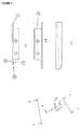
- a slide pad (1) for aligning a constant distance between the rim edge wall (2) and the back side (3) of the bead part (4) of a tyre (5), wherein the slide pad (1) has a length of at least 50 mm, a height between 1 and 15 mm and a thickness between 2 and 9 mm, wherein one of the surface of the slide pad (1) being defined by the length and the thickness of the slide pad defines the lower side (6), the other rear (opposed) surface of the slide pad (1) being defined by the length and the thickness of the slide pad defines the upper side (7), one of the surface of the slide pad (1) being defined by the height and the thickness of the slide pad (1) defines the insertion front (8), the other rear (opposed) surface of the slide pad (1) being defined by the height and the thickness of the slide pad (1) defines the insertion end (9), and wherein the upper side (7) of the insertion front (8) of the slide pad (1) has a smaller thickness than the lower side (6) of the insertion front.
- This slide pad (1) has the major advantage that it is a simple device for adjusting the bead part (4) of a tyre precisely on a rim without moving the bead part (4) over the hump of the rim (14).
- the use of this slide pad (1) more effectively leads to a constant gap between the bead part (4) and the outer wall of the rim (14).
- This resulting matching of the bead structure is the key knowledge to provide an optimized way to the market providing an optimal tyre setup, especially in the formula one and for sports cars, reducing vibrations resulting from an incorrect adjustment of the bead part (4) on the tyre (5).
- the improvement when using the slide pad (1) according to the invention is a higher precision tyre mount work in a shorter time compared with the tools and principles of the prior art.
- the thickness of the slide pad (1) is important and increases from the insertion-edge- part to the end of the tip-part. This structure avoids the instability of positioning due to the return of bead part (4) caused by elasticity of rubber.
- a preferred embodiment of the slide pad according to the invention has a length between 110 and 150 mm.
- the slide pad (1) could have a height between 2 and 5 mm and/or a thickness between 3 and 5 mm.
- Another preferred embodiment of the invention relates to a slide pad (1) having a thickness at the insertion end (9) which is between 2 and 8 times thicker than the thickness of the insertion front (8).
- the thickness of the slide pad (1) at the insertion end (9) is 6 mm and the thickness of the insertion front (8) is 1 mm.
- the present invention preferably also relates to a slide pad (1) which comprises further a wedge angle between the height at the insertion front (8) and the height at the insertion end (9) of 1 to 5 degrees.
- the present invention further relates to a slide pad (1) which comprises further a friction reducing matter.
- This friction reducing matter could comprise a small dimple, roller and/or ball.
- the size of the small dimple could be less than 2 mm in diameter and less than 1 mm in depth. It is also possible to use friction reducing matter comprising a coating containing friction reducing particles (PTFE, MoS 2 ).
- the friction reducing matter provides an efficient and simple way leading to a perfect alignment and tyre/rim-setup.
- the size of the small dimple of less than 2 mm in diameter and less than 1 mm in depth are put on the contact side to the tyre rubber, considering the characteristic of the rubber to lower the contact pressure in a best mode.
- the slide pad (1) comprises further a bracket which is located at the upper side (7) of the slide pad (1) between the insertion front (8) and the insertion end (9).
- This slide pad (1) could comprise further fixing means (12) for attaching the slide pad (1) to an adjusting machine.
- an automatically adjusting of many tyres is provided.
- the invention relates to a process for aligning a bead part (4) of a tyre (5) on the rim (14) with a slide pad (1) wherein
Landscapes
- Engineering & Computer Science (AREA)
- Mechanical Engineering (AREA)
- Tires In General (AREA)
Claims (13)
- Ein Gleitstück (2) zum Ausrichten eines konstanten Abstandes zwischen der Felgenhornwand und Rückseite (3) eines Wulstteils (4) eine Reifens (5), dadurch gekennzeichnet, dassa) es eine Länge von mindestens 50 mm hat,b) es eine Höhe zwischen 1 und 15 mm hat,c) es eine Dicke zwischen 2 und 9 mm hat,d) eine der Oberflächen, die durch die Länge und die Dicke des Gleitstücks (1) gebildet ist, eine Unterseite (6) definiert,e) die von d) verschiedene Oberfläche, die durch die Länge und die Dicke des Gleitstücks (1) gebildet ist, die Oberseite (7) definiert; Oberfläche e) liegt der Oberfläche d) gegenüber,f) eine der Oberflächen, die durch die Höhe und die Dicke des Gleitstücks (1) gebildet ist, eine Einsteckvorderseite (8) definiert,g) die von f) verschiedene Oberfläche, die durch die Höhe und die Dicke des Gleitstücks (1) gebildet ist, das Einsteckende (9) definiert; die Oberfläche g) liegt der Oberfläche f) gegenüber,
und dadurch, dass die Oberseite (7) der Einsteckvorderseite (8) des Gleitstücks (1) eine geringere Dicke als die untere Seite (6) der Einsteckvorderseite (8) aufweist. - Ein Gleitstück (1) gemäß Anspruch 1, dadurch gekennzeichnet, dass es eine Länge zwischen 110 und 150 hat.
- Ein Gleitstück (1) gemäß Anspruch 1 oder 2, dadurch gekennzeichnet, dass es eine Höhe zwischen 2 und 5 mm hat.
- Ein Gleitstück (1) nach einem der vorstehenden Ansprüche, dadurch gekennzeichnet, dass es eine Dicke zwischen 3 und 5 mm hat.
- Ein Gleitstück (1) gemäß Anspruch 1, dadurch gekennzeichnet, dass die Dicke des Gleitstücks (1) am Einsteckende (9) zwischen 2 und 8 mal dicker als die Dicke der Einsteckvorderseite (8) ist.
- Ein Gleitstück (1) gemäß einem der vorstehenden Ansprüche, dadurch gekennzeichnet, dass es zusätzlich einen Keilwinkel zwischen der Höhe der Einsteckvorderseite (8) und der Höhe des Einsteckendes (9) von 1 bis 5° aufweist.
- Ein Gleitstück (1) nach einem der vorstehenden Ansprüche, dadurch gekennzeichnet, dass es zusätzlich ein Reibung reduzierendes Material (10) aufweist.
- Ein Gleitstück (1) gemäß Anspruch 7, dadurch gekennzeichnet, dass das Reibung reduzierende Material (10) ein kleines Grübchen, Walze und/oder Kugel ist.
- Ein Gleitstück (1) gemäß Anspruch 8, dadurch gekennzeichnet, dass die Größe der kleinen Grübchen kleiner als 2 mm im Durchmesser und kleiner als 1 mm in der Tiefe ist.
- Ein Gleitstück (1) gemäß Anspruch 7, dadurch gekennzeichnet, dass das Reibung reduzierende Material (10) eine Beschichtung mit Reibung reduzierenden Partikeln (PTFE, MoS2) aufweist.
- Ein Gleitstück (1) gemäß einem der vorstehenden Ansprüche, dadurch gekennzeichnet, dass es zusätzlich ein Halteblech aufweist, das an der oberen Seite (7) des Gleitstücks (1) zwischen der Einsteckvorderseite (8) und dem Einsteckende (9) angeordnet ist.
- Ein Gleitstück (1) gemäß Anspruch 11, dadurch gekennzeichnet, dass es außerdem Befestigungsmittel (12) zur Befestigung des Gleitstücks (1) an eine Justiermaschine aufweist
- Ein Verfahren zum Ausrichten eines Wulstteils (4) eines Reifens (5) auf dem Wulstsitzbereich (18) zwischen der inneren Seitenwand (17) und dem Hump (21) einer Felge (14) mit einem Gleitstück (1) gemäß einem der vorstehenden Ansprüche, dadurch gekennzeichnet, dass• in einem ersten Schritt das Gleitstück (1) oberhalb des äußeren umlaufenden Endes (15) der Felge (14) positioniert wird und einen ausreichenden Druck auf die äußere Seitenwand des rotierenden Reifens (5) derart ausübt, dass die Rückwand (3) des Wulstteils (4) des Reifens (5) von dem äußersten Ende des äußeren Umfangs der Felgenhornwand (2) abgerückt wird,• in einem zweiten Schritt das Gleitstück (1) verschwenkt und so in eine Richtung bewegt wird, dass es zwischen die äußere Seitenwand des Reifens (5) und die innere Wand (17) der Felgenhornwand (2) hinein gleitet, und• in einem dritten Schritt das Gleitstück (1) verschwenkt und so in eine Richtung bewegt wird, dass es einen Druck auf die Rückseite des Wulstteils (3) ausübt, der hauptsächlich parallel zum Wulstsitzbereich (18) der Felge (14) in Richtung zur Wulstzehe (19) gerichtet ist, so dass die Wulstsohle (20) in Richtung zum Hump (21) bewegt wird und dabei eine axiale Bewegung ausübt.
Priority Applications (1)
| Application Number | Priority Date | Filing Date | Title |
|---|---|---|---|
| EP20070109756 EP2000334B1 (de) | 2007-06-06 | 2007-06-06 | Gleitauflage |
Applications Claiming Priority (1)
| Application Number | Priority Date | Filing Date | Title |
|---|---|---|---|
| EP20070109756 EP2000334B1 (de) | 2007-06-06 | 2007-06-06 | Gleitauflage |
Publications (2)
| Publication Number | Publication Date |
|---|---|
| EP2000334A1 EP2000334A1 (de) | 2008-12-10 |
| EP2000334B1 true EP2000334B1 (de) | 2014-10-08 |
Family
ID=38616399
Family Applications (1)
| Application Number | Title | Priority Date | Filing Date |
|---|---|---|---|
| EP20070109756 Active EP2000334B1 (de) | 2007-06-06 | 2007-06-06 | Gleitauflage |
Country Status (1)
| Country | Link |
|---|---|
| EP (1) | EP2000334B1 (de) |
Family Cites Families (2)
| Publication number | Priority date | Publication date | Assignee | Title |
|---|---|---|---|---|
| US2421856A (en) * | 1944-06-27 | 1947-06-10 | Otto V Teegarden | Tire replacing tool |
| US2661793A (en) * | 1947-07-02 | 1953-12-08 | Rockwell Hugh Monroe | Circumferentially traveling type tire mounting and demounting apparatus |
-
2007
- 2007-06-06 EP EP20070109756 patent/EP2000334B1/de active Active
Also Published As
| Publication number | Publication date |
|---|---|
| EP2000334A1 (de) | 2008-12-10 |
Similar Documents
| Publication | Publication Date | Title |
|---|---|---|
| EP1157860B1 (de) | Reifenabdrückvorrichtung für ein Raddemontiergerät, und Raddemontiergerät mit einer solchen Vorrichtung | |
| JP6866176B2 (ja) | タイヤからバリを除去する方法及び装置 | |
| CN101279512A (zh) | 将橡胶条安装至轮胎毛坯的设备、装置和方法 | |
| US7371158B2 (en) | Plating removing apparatus for two-piece wheel | |
| EP2000334B1 (de) | Gleitauflage | |
| CN216176340U (zh) | 全自动铆接机 | |
| US20190061444A1 (en) | Method and apparatus for mounting a tire | |
| CN110814980B (zh) | 提高胎圈钢丝表面粗糙度的装置 | |
| EP1314583B1 (de) | Einrichtung zum Einschieben und Herausziehen von einem Stützring in einem Reifen | |
| KR101218330B1 (ko) | 표면 가공장치 | |
| JP4797223B2 (ja) | ロードホイールの仕上げ装置および仕上げ方法 | |
| KR20220039453A (ko) | 동파이프 축관 자동 스웨징 장치 | |
| JP5819940B2 (ja) | タイヤの構成要素部の製造方法及びその装置 | |
| CN218801250U (zh) | 一种铝型材加工用打磨机构 | |
| CN118789383B (zh) | 一种汽车零配件加工用去毛刺装置 | |
| CN223012780U (zh) | 一种钢材加工用磨光机 | |
| CN224011362U (zh) | 一种用于模具钢锯床上的下料工装 | |
| WO2006132630A2 (en) | Method and apparatus for mounting a tire | |
| JPH06285702A (ja) | それぞれ踏面とフランジ面からなる鉄道車両輪軸の車輪外周面を削正する方法およびこの方法を実施するための床上旋盤 | |
| CN121290218A (zh) | 一种硬脆异径回转体工件的均匀研磨抛光装置及方法 | |
| CN108698351A (zh) | 用于胎面翻新精加工中的沟槽支撑的刻纹鼓 | |
| CN120243995A (zh) | 一种转子车削装置 | |
| CN114654748A (zh) | 一种用于安装软塞的装置以及旋转装入软塞的方法 | |
| CN117381645A (zh) | 一种汽车钳体毛坯加工装置及加工方法 | |
| CN117340745A (zh) | 一种带锯条底边抛光装置及方法 |
Legal Events
| Date | Code | Title | Description |
|---|---|---|---|
| PUAI | Public reference made under article 153(3) epc to a published international application that has entered the european phase |
Free format text: ORIGINAL CODE: 0009012 |
|
| 17P | Request for examination filed |
Effective date: 20080519 |
|
| AK | Designated contracting states |
Kind code of ref document: A1 Designated state(s): AT BE BG CH CY CZ DE DK EE ES FI FR GB GR HU IE IS IT LI LT LU LV MC MT NL PL PT RO SE SI SK TR |
|
| AX | Request for extension of the european patent |
Extension state: AL BA HR MK RS |
|
| AKX | Designation fees paid |
Designated state(s): AT BE BG CH CY CZ DE DK EE ES FI FR GB GR HU IE IS IT LI LT LU LV MC MT NL PL PT RO SE SI SK TR |
|
| 18D | Application deemed to be withdrawn |
Effective date: 20100701 |
|
| 18RA | Request filed for re-establishment of rights before grant |
Effective date: 20111208 |
|
| D18D | Application deemed to be withdrawn (deleted) | ||
| GRAP | Despatch of communication of intention to grant a patent |
Free format text: ORIGINAL CODE: EPIDOSNIGR1 |
|
| INTG | Intention to grant announced |
Effective date: 20140423 |
|
| GRAS | Grant fee paid |
Free format text: ORIGINAL CODE: EPIDOSNIGR3 |
|
| GRAA | (expected) grant |
Free format text: ORIGINAL CODE: 0009210 |
|
| AK | Designated contracting states |
Kind code of ref document: B1 Designated state(s): AT BE BG CH CY CZ DE DK EE ES FI FR GB GR HU IE IS IT LI LT LU LV MC MT NL PL PT RO SE SI SK TR |
|
| REG | Reference to a national code |
Ref country code: AT Ref legal event code: REF Ref document number: 690386 Country of ref document: AT Kind code of ref document: T Effective date: 20141015 Ref country code: CH Ref legal event code: EP |
|
| REG | Reference to a national code |
Ref country code: IE Ref legal event code: FG4D |
|
| REG | Reference to a national code |
Ref country code: DE Ref legal event code: R096 Ref document number: 602007038801 Country of ref document: DE Effective date: 20141120 |
|
| REG | Reference to a national code |
Ref country code: NL Ref legal event code: VDEP Effective date: 20141008 |
|
| REG | Reference to a national code |
Ref country code: AT Ref legal event code: MK05 Ref document number: 690386 Country of ref document: AT Kind code of ref document: T Effective date: 20141008 |
|
| REG | Reference to a national code |
Ref country code: LT Ref legal event code: MG4D |
|
| PG25 | Lapsed in a contracting state [announced via postgrant information from national office to epo] |
Ref country code: NL Free format text: LAPSE BECAUSE OF FAILURE TO SUBMIT A TRANSLATION OF THE DESCRIPTION OR TO PAY THE FEE WITHIN THE PRESCRIBED TIME-LIMIT Effective date: 20141008 |
|
| PG25 | Lapsed in a contracting state [announced via postgrant information from national office to epo] |
Ref country code: FI Free format text: LAPSE BECAUSE OF FAILURE TO SUBMIT A TRANSLATION OF THE DESCRIPTION OR TO PAY THE FEE WITHIN THE PRESCRIBED TIME-LIMIT Effective date: 20141008 Ref country code: ES Free format text: LAPSE BECAUSE OF FAILURE TO SUBMIT A TRANSLATION OF THE DESCRIPTION OR TO PAY THE FEE WITHIN THE PRESCRIBED TIME-LIMIT Effective date: 20141008 Ref country code: LT Free format text: LAPSE BECAUSE OF FAILURE TO SUBMIT A TRANSLATION OF THE DESCRIPTION OR TO PAY THE FEE WITHIN THE PRESCRIBED TIME-LIMIT Effective date: 20141008 Ref country code: PT Free format text: LAPSE BECAUSE OF FAILURE TO SUBMIT A TRANSLATION OF THE DESCRIPTION OR TO PAY THE FEE WITHIN THE PRESCRIBED TIME-LIMIT Effective date: 20150209 Ref country code: IS Free format text: LAPSE BECAUSE OF FAILURE TO SUBMIT A TRANSLATION OF THE DESCRIPTION OR TO PAY THE FEE WITHIN THE PRESCRIBED TIME-LIMIT Effective date: 20150208 |
|
| PG25 | Lapsed in a contracting state [announced via postgrant information from national office to epo] |
Ref country code: CY Free format text: LAPSE BECAUSE OF FAILURE TO SUBMIT A TRANSLATION OF THE DESCRIPTION OR TO PAY THE FEE WITHIN THE PRESCRIBED TIME-LIMIT Effective date: 20141008 Ref country code: LV Free format text: LAPSE BECAUSE OF FAILURE TO SUBMIT A TRANSLATION OF THE DESCRIPTION OR TO PAY THE FEE WITHIN THE PRESCRIBED TIME-LIMIT Effective date: 20141008 Ref country code: GR Free format text: LAPSE BECAUSE OF FAILURE TO SUBMIT A TRANSLATION OF THE DESCRIPTION OR TO PAY THE FEE WITHIN THE PRESCRIBED TIME-LIMIT Effective date: 20150109 Ref country code: SE Free format text: LAPSE BECAUSE OF FAILURE TO SUBMIT A TRANSLATION OF THE DESCRIPTION OR TO PAY THE FEE WITHIN THE PRESCRIBED TIME-LIMIT Effective date: 20141008 Ref country code: PL Free format text: LAPSE BECAUSE OF FAILURE TO SUBMIT A TRANSLATION OF THE DESCRIPTION OR TO PAY THE FEE WITHIN THE PRESCRIBED TIME-LIMIT Effective date: 20141008 Ref country code: AT Free format text: LAPSE BECAUSE OF FAILURE TO SUBMIT A TRANSLATION OF THE DESCRIPTION OR TO PAY THE FEE WITHIN THE PRESCRIBED TIME-LIMIT Effective date: 20141008 |
|
| REG | Reference to a national code |
Ref country code: DE Ref legal event code: R097 Ref document number: 602007038801 Country of ref document: DE |
|
| PG25 | Lapsed in a contracting state [announced via postgrant information from national office to epo] |
Ref country code: EE Free format text: LAPSE BECAUSE OF FAILURE TO SUBMIT A TRANSLATION OF THE DESCRIPTION OR TO PAY THE FEE WITHIN THE PRESCRIBED TIME-LIMIT Effective date: 20141008 Ref country code: RO Free format text: LAPSE BECAUSE OF FAILURE TO SUBMIT A TRANSLATION OF THE DESCRIPTION OR TO PAY THE FEE WITHIN THE PRESCRIBED TIME-LIMIT Effective date: 20141008 Ref country code: CZ Free format text: LAPSE BECAUSE OF FAILURE TO SUBMIT A TRANSLATION OF THE DESCRIPTION OR TO PAY THE FEE WITHIN THE PRESCRIBED TIME-LIMIT Effective date: 20141008 Ref country code: DK Free format text: LAPSE BECAUSE OF FAILURE TO SUBMIT A TRANSLATION OF THE DESCRIPTION OR TO PAY THE FEE WITHIN THE PRESCRIBED TIME-LIMIT Effective date: 20141008 Ref country code: SK Free format text: LAPSE BECAUSE OF FAILURE TO SUBMIT A TRANSLATION OF THE DESCRIPTION OR TO PAY THE FEE WITHIN THE PRESCRIBED TIME-LIMIT Effective date: 20141008 |
|
| PLBE | No opposition filed within time limit |
Free format text: ORIGINAL CODE: 0009261 |
|
| STAA | Information on the status of an ep patent application or granted ep patent |
Free format text: STATUS: NO OPPOSITION FILED WITHIN TIME LIMIT |
|
| 26N | No opposition filed |
Effective date: 20150709 |
|
| PG25 | Lapsed in a contracting state [announced via postgrant information from national office to epo] |
Ref country code: MC Free format text: LAPSE BECAUSE OF FAILURE TO SUBMIT A TRANSLATION OF THE DESCRIPTION OR TO PAY THE FEE WITHIN THE PRESCRIBED TIME-LIMIT Effective date: 20141008 |
|
| PG25 | Lapsed in a contracting state [announced via postgrant information from national office to epo] |
Ref country code: SI Free format text: LAPSE BECAUSE OF FAILURE TO SUBMIT A TRANSLATION OF THE DESCRIPTION OR TO PAY THE FEE WITHIN THE PRESCRIBED TIME-LIMIT Effective date: 20141008 Ref country code: LU Free format text: LAPSE BECAUSE OF FAILURE TO SUBMIT A TRANSLATION OF THE DESCRIPTION OR TO PAY THE FEE WITHIN THE PRESCRIBED TIME-LIMIT Effective date: 20150606 |
|
| REG | Reference to a national code |
Ref country code: IE Ref legal event code: MM4A |
|
| REG | Reference to a national code |
Ref country code: FR Ref legal event code: ST Effective date: 20160229 |
|
| PG25 | Lapsed in a contracting state [announced via postgrant information from national office to epo] |
Ref country code: IE Free format text: LAPSE BECAUSE OF NON-PAYMENT OF DUE FEES Effective date: 20150606 |
|
| PG25 | Lapsed in a contracting state [announced via postgrant information from national office to epo] |
Ref country code: FR Free format text: LAPSE BECAUSE OF NON-PAYMENT OF DUE FEES Effective date: 20150630 |
|
| PG25 | Lapsed in a contracting state [announced via postgrant information from national office to epo] |
Ref country code: MT Free format text: LAPSE BECAUSE OF FAILURE TO SUBMIT A TRANSLATION OF THE DESCRIPTION OR TO PAY THE FEE WITHIN THE PRESCRIBED TIME-LIMIT Effective date: 20141008 |
|
| PG25 | Lapsed in a contracting state [announced via postgrant information from national office to epo] |
Ref country code: BG Free format text: LAPSE BECAUSE OF FAILURE TO SUBMIT A TRANSLATION OF THE DESCRIPTION OR TO PAY THE FEE WITHIN THE PRESCRIBED TIME-LIMIT Effective date: 20141008 Ref country code: HU Free format text: LAPSE BECAUSE OF FAILURE TO SUBMIT A TRANSLATION OF THE DESCRIPTION OR TO PAY THE FEE WITHIN THE PRESCRIBED TIME-LIMIT; INVALID AB INITIO Effective date: 20070606 |
|
| PG25 | Lapsed in a contracting state [announced via postgrant information from national office to epo] |
Ref country code: TR Free format text: LAPSE BECAUSE OF FAILURE TO SUBMIT A TRANSLATION OF THE DESCRIPTION OR TO PAY THE FEE WITHIN THE PRESCRIBED TIME-LIMIT Effective date: 20141008 |
|
| PG25 | Lapsed in a contracting state [announced via postgrant information from national office to epo] |
Ref country code: BE Free format text: LAPSE BECAUSE OF FAILURE TO SUBMIT A TRANSLATION OF THE DESCRIPTION OR TO PAY THE FEE WITHIN THE PRESCRIBED TIME-LIMIT Effective date: 20141008 |
|
| PGFP | Annual fee paid to national office [announced via postgrant information from national office to epo] |
Ref country code: CH Payment date: 20180615 Year of fee payment: 12 |
|
| PGFP | Annual fee paid to national office [announced via postgrant information from national office to epo] |
Ref country code: GB Payment date: 20180612 Year of fee payment: 12 Ref country code: IT Payment date: 20180622 Year of fee payment: 12 |
|
| REG | Reference to a national code |
Ref country code: CH Ref legal event code: PL |
|
| GBPC | Gb: european patent ceased through non-payment of renewal fee |
Effective date: 20190606 |
|
| PG25 | Lapsed in a contracting state [announced via postgrant information from national office to epo] |
Ref country code: IT Free format text: LAPSE BECAUSE OF NON-PAYMENT OF DUE FEES Effective date: 20190606 Ref country code: GB Free format text: LAPSE BECAUSE OF NON-PAYMENT OF DUE FEES Effective date: 20190606 |
|
| PG25 | Lapsed in a contracting state [announced via postgrant information from national office to epo] |
Ref country code: CH Free format text: LAPSE BECAUSE OF NON-PAYMENT OF DUE FEES Effective date: 20190630 Ref country code: LI Free format text: LAPSE BECAUSE OF NON-PAYMENT OF DUE FEES Effective date: 20190630 |
|
| PGFP | Annual fee paid to national office [announced via postgrant information from national office to epo] |
Ref country code: DE Payment date: 20250826 Year of fee payment: 19 |