EP2000215A2 - Sprühvorrichtung - Google Patents
Sprühvorrichtung Download PDFInfo
- Publication number
- EP2000215A2 EP2000215A2 EP08156518A EP08156518A EP2000215A2 EP 2000215 A2 EP2000215 A2 EP 2000215A2 EP 08156518 A EP08156518 A EP 08156518A EP 08156518 A EP08156518 A EP 08156518A EP 2000215 A2 EP2000215 A2 EP 2000215A2
- Authority
- EP
- European Patent Office
- Prior art keywords
- liquid
- gas
- tube
- orifice
- sprayer
- Prior art date
- Legal status (The legal status is an assumption and is not a legal conclusion. Google has not performed a legal analysis and makes no representation as to the accuracy of the status listed.)
- Withdrawn
Links
- 239000007788 liquid Substances 0.000 claims abstract description 274
- 239000000203 mixture Substances 0.000 claims description 20
- 239000012530 fluid Substances 0.000 claims 2
- 239000000463 material Substances 0.000 description 24
- 238000000889 atomisation Methods 0.000 description 10
- 238000003825 pressing Methods 0.000 description 8
- 210000003813 thumb Anatomy 0.000 description 8
- 230000002093 peripheral effect Effects 0.000 description 7
- 210000003811 finger Anatomy 0.000 description 5
- 230000008602 contraction Effects 0.000 description 4
- 239000004033 plastic Substances 0.000 description 4
- 229920003023 plastic Polymers 0.000 description 4
- 238000005507 spraying Methods 0.000 description 4
- 230000008859 change Effects 0.000 description 3
- 238000010276 construction Methods 0.000 description 3
- 238000002357 laparoscopic surgery Methods 0.000 description 3
- 239000007921 spray Substances 0.000 description 3
- -1 succinimidyl Chemical group 0.000 description 3
- CURLTUGMZLYLDI-UHFFFAOYSA-N Carbon dioxide Chemical compound O=C=O CURLTUGMZLYLDI-UHFFFAOYSA-N 0.000 description 2
- 229910052782 aluminium Inorganic materials 0.000 description 2
- XAGFODPZIPBFFR-UHFFFAOYSA-N aluminium Chemical compound [Al] XAGFODPZIPBFFR-UHFFFAOYSA-N 0.000 description 2
- 229920005549 butyl rubber Polymers 0.000 description 2
- 229920001971 elastomer Polymers 0.000 description 2
- 239000004615 ingredient Substances 0.000 description 2
- 238000004519 manufacturing process Methods 0.000 description 2
- 239000007769 metal material Substances 0.000 description 2
- 229920003052 natural elastomer Polymers 0.000 description 2
- 229920001194 natural rubber Polymers 0.000 description 2
- 230000004044 response Effects 0.000 description 2
- 239000010935 stainless steel Substances 0.000 description 2
- 229910001220 stainless steel Inorganic materials 0.000 description 2
- 238000011144 upstream manufacturing Methods 0.000 description 2
- 229920001353 Dextrin Polymers 0.000 description 1
- 239000004375 Dextrin Substances 0.000 description 1
- 108010049003 Fibrinogen Proteins 0.000 description 1
- 102000008946 Fibrinogen Human genes 0.000 description 1
- 244000043261 Hevea brasiliensis Species 0.000 description 1
- 239000004698 Polyethylene Substances 0.000 description 1
- 239000004743 Polypropylene Substances 0.000 description 1
- 108090000190 Thrombin Proteins 0.000 description 1
- 239000000853 adhesive Substances 0.000 description 1
- 230000001070 adhesive effect Effects 0.000 description 1
- 230000000181 anti-adherent effect Effects 0.000 description 1
- 210000000746 body region Anatomy 0.000 description 1
- 229910002092 carbon dioxide Inorganic materials 0.000 description 1
- 239000001569 carbon dioxide Substances 0.000 description 1
- 238000006243 chemical reaction Methods 0.000 description 1
- 230000006835 compression Effects 0.000 description 1
- 238000007906 compression Methods 0.000 description 1
- 230000008878 coupling Effects 0.000 description 1
- 238000010168 coupling process Methods 0.000 description 1
- 238000005859 coupling reaction Methods 0.000 description 1
- 230000003247 decreasing effect Effects 0.000 description 1
- 235000019425 dextrin Nutrition 0.000 description 1
- BNIILDVGGAEEIG-UHFFFAOYSA-L disodium hydrogen phosphate Chemical compound [Na+].[Na+].OP([O-])([O-])=O BNIILDVGGAEEIG-UHFFFAOYSA-L 0.000 description 1
- 239000013013 elastic material Substances 0.000 description 1
- 229940012952 fibrinogen Drugs 0.000 description 1
- 239000011344 liquid material Substances 0.000 description 1
- 239000003550 marker Substances 0.000 description 1
- 230000007246 mechanism Effects 0.000 description 1
- 229920000573 polyethylene Polymers 0.000 description 1
- 229920001155 polypropylene Polymers 0.000 description 1
- 229920000915 polyvinyl chloride Polymers 0.000 description 1
- 239000004800 polyvinyl chloride Substances 0.000 description 1
- 230000009467 reduction Effects 0.000 description 1
- 239000012858 resilient material Substances 0.000 description 1
- 239000011347 resin Substances 0.000 description 1
- 229920005989 resin Polymers 0.000 description 1
- 229920002379 silicone rubber Polymers 0.000 description 1
- 239000004945 silicone rubber Substances 0.000 description 1
- 238000007711 solidification Methods 0.000 description 1
- 230000008023 solidification Effects 0.000 description 1
- 239000002904 solvent Substances 0.000 description 1
- 239000000126 substance Substances 0.000 description 1
- 229960004072 thrombin Drugs 0.000 description 1
- 239000003106 tissue adhesive Substances 0.000 description 1
- 230000000007 visual effect Effects 0.000 description 1
- 238000004804 winding Methods 0.000 description 1
Images


Classifications
-
- B—PERFORMING OPERATIONS; TRANSPORTING
- B05—SPRAYING OR ATOMISING IN GENERAL; APPLYING FLUENT MATERIALS TO SURFACES, IN GENERAL
- B05B—SPRAYING APPARATUS; ATOMISING APPARATUS; NOZZLES
- B05B7/00—Spraying apparatus for discharge of liquids or other fluent materials from two or more sources, e.g. of liquid and air, of powder and gas
- B05B7/02—Spray pistols; Apparatus for discharge
- B05B7/06—Spray pistols; Apparatus for discharge with at least one outlet orifice surrounding another approximately in the same plane
- B05B7/062—Spray pistols; Apparatus for discharge with at least one outlet orifice surrounding another approximately in the same plane with only one liquid outlet and at least one gas outlet
- B05B7/066—Spray pistols; Apparatus for discharge with at least one outlet orifice surrounding another approximately in the same plane with only one liquid outlet and at least one gas outlet with an inner liquid outlet surrounded by at least one annular gas outlet
-
- A—HUMAN NECESSITIES
- A61—MEDICAL OR VETERINARY SCIENCE; HYGIENE
- A61B—DIAGNOSIS; SURGERY; IDENTIFICATION
- A61B17/00—Surgical instruments, devices or methods
- A61B17/00491—Surgical glue applicators
-
- B—PERFORMING OPERATIONS; TRANSPORTING
- B01—PHYSICAL OR CHEMICAL PROCESSES OR APPARATUS IN GENERAL
- B01F—MIXING, e.g. DISSOLVING, EMULSIFYING OR DISPERSING
- B01F25/00—Flow mixers; Mixers for falling materials, e.g. solid particles
- B01F25/20—Jet mixers, i.e. mixers using high-speed fluid streams
- B01F25/23—Mixing by intersecting jets
- B01F25/231—Mixing by intersecting jets the intersecting jets having the configuration of sheets, cylinders or cones
-
- B—PERFORMING OPERATIONS; TRANSPORTING
- B01—PHYSICAL OR CHEMICAL PROCESSES OR APPARATUS IN GENERAL
- B01F—MIXING, e.g. DISSOLVING, EMULSIFYING OR DISPERSING
- B01F33/00—Other mixers; Mixing plants; Combinations of mixers
- B01F33/50—Movable or transportable mixing devices or plants
- B01F33/501—Movable mixing devices, i.e. readily shifted or displaced from one place to another, e.g. portable during use
- B01F33/5011—Movable mixing devices, i.e. readily shifted or displaced from one place to another, e.g. portable during use portable during use, e.g. hand-held
- B01F33/50112—Movable mixing devices, i.e. readily shifted or displaced from one place to another, e.g. portable during use portable during use, e.g. hand-held of the syringe or cartridge type
-
- B—PERFORMING OPERATIONS; TRANSPORTING
- B01—PHYSICAL OR CHEMICAL PROCESSES OR APPARATUS IN GENERAL
- B01F—MIXING, e.g. DISSOLVING, EMULSIFYING OR DISPERSING
- B01F35/00—Accessories for mixers; Auxiliary operations or auxiliary devices; Parts or details of general application
- B01F35/50—Mixing receptacles
- B01F35/52—Receptacles with two or more compartments
- B01F35/522—Receptacles with two or more compartments comprising compartments keeping the materials to be mixed separated until the mixing is initiated
-
- B—PERFORMING OPERATIONS; TRANSPORTING
- B05—SPRAYING OR ATOMISING IN GENERAL; APPLYING FLUENT MATERIALS TO SURFACES, IN GENERAL
- B05B—SPRAYING APPARATUS; ATOMISING APPARATUS; NOZZLES
- B05B7/00—Spraying apparatus for discharge of liquids or other fluent materials from two or more sources, e.g. of liquid and air, of powder and gas
- B05B7/02—Spray pistols; Apparatus for discharge
- B05B7/08—Spray pistols; Apparatus for discharge with separate outlet orifices, e.g. to form parallel jets, i.e. the axis of the jets being parallel, to form intersecting jets, i.e. the axis of the jets converging but not necessarily intersecting at a point
- B05B7/0807—Spray pistols; Apparatus for discharge with separate outlet orifices, e.g. to form parallel jets, i.e. the axis of the jets being parallel, to form intersecting jets, i.e. the axis of the jets converging but not necessarily intersecting at a point to form intersecting jets
- B05B7/0861—Spray pistols; Apparatus for discharge with separate outlet orifices, e.g. to form parallel jets, i.e. the axis of the jets being parallel, to form intersecting jets, i.e. the axis of the jets converging but not necessarily intersecting at a point to form intersecting jets with one single jet constituted by a liquid or a mixture containing a liquid and several gas jets
-
- B—PERFORMING OPERATIONS; TRANSPORTING
- B05—SPRAYING OR ATOMISING IN GENERAL; APPLYING FLUENT MATERIALS TO SURFACES, IN GENERAL
- B05B—SPRAYING APPARATUS; ATOMISING APPARATUS; NOZZLES
- B05B7/00—Spraying apparatus for discharge of liquids or other fluent materials from two or more sources, e.g. of liquid and air, of powder and gas
- B05B7/02—Spray pistols; Apparatus for discharge
- B05B7/08—Spray pistols; Apparatus for discharge with separate outlet orifices, e.g. to form parallel jets, i.e. the axis of the jets being parallel, to form intersecting jets, i.e. the axis of the jets converging but not necessarily intersecting at a point
- B05B7/0876—Spray pistols; Apparatus for discharge with separate outlet orifices, e.g. to form parallel jets, i.e. the axis of the jets being parallel, to form intersecting jets, i.e. the axis of the jets converging but not necessarily intersecting at a point to form parallel jets constituted by a liquid or a mixture containing a liquid
-
- B—PERFORMING OPERATIONS; TRANSPORTING
- B05—SPRAYING OR ATOMISING IN GENERAL; APPLYING FLUENT MATERIALS TO SURFACES, IN GENERAL
- B05B—SPRAYING APPARATUS; ATOMISING APPARATUS; NOZZLES
- B05B7/00—Spraying apparatus for discharge of liquids or other fluent materials from two or more sources, e.g. of liquid and air, of powder and gas
- B05B7/02—Spray pistols; Apparatus for discharge
- B05B7/12—Spray pistols; Apparatus for discharge designed to control volume of flow, e.g. with adjustable passages
-
- B—PERFORMING OPERATIONS; TRANSPORTING
- B05—SPRAYING OR ATOMISING IN GENERAL; APPLYING FLUENT MATERIALS TO SURFACES, IN GENERAL
- B05B—SPRAYING APPARATUS; ATOMISING APPARATUS; NOZZLES
- B05B7/00—Spraying apparatus for discharge of liquids or other fluent materials from two or more sources, e.g. of liquid and air, of powder and gas
- B05B7/24—Spraying apparatus for discharge of liquids or other fluent materials from two or more sources, e.g. of liquid and air, of powder and gas with means, e.g. a container, for supplying liquid or other fluent material to a discharge device
- B05B7/2402—Apparatus to be carried on or by a person, e.g. by hand; Apparatus comprising containers fixed to the discharge device
- B05B7/2472—Apparatus to be carried on or by a person, e.g. by hand; Apparatus comprising containers fixed to the discharge device comprising several containers
-
- A—HUMAN NECESSITIES
- A61—MEDICAL OR VETERINARY SCIENCE; HYGIENE
- A61B—DIAGNOSIS; SURGERY; IDENTIFICATION
- A61B17/00—Surgical instruments, devices or methods
- A61B17/00491—Surgical glue applicators
- A61B2017/00495—Surgical glue applicators for two-component glue
-
- A—HUMAN NECESSITIES
- A61—MEDICAL OR VETERINARY SCIENCE; HYGIENE
- A61B—DIAGNOSIS; SURGERY; IDENTIFICATION
- A61B17/00—Surgical instruments, devices or methods
- A61B2017/00535—Surgical instruments, devices or methods pneumatically or hydraulically operated
- A61B2017/00544—Surgical instruments, devices or methods pneumatically or hydraulically operated pneumatically
- A61B2017/00548—Gas cartridges therefor
-
- B—PERFORMING OPERATIONS; TRANSPORTING
- B05—SPRAYING OR ATOMISING IN GENERAL; APPLYING FLUENT MATERIALS TO SURFACES, IN GENERAL
- B05C—APPARATUS FOR APPLYING FLUENT MATERIALS TO SURFACES, IN GENERAL
- B05C17/00—Hand tools or apparatus using hand held tools, for applying liquids or other fluent materials to, for spreading applied liquids or other fluent materials on, or for partially removing applied liquids or other fluent materials from, surfaces
- B05C17/005—Hand tools or apparatus using hand held tools, for applying liquids or other fluent materials to, for spreading applied liquids or other fluent materials on, or for partially removing applied liquids or other fluent materials from, surfaces for discharging material from a reservoir or container located in or on the hand tool through an outlet orifice by pressure without using surface contacting members like pads or brushes
- B05C17/00553—Hand tools or apparatus using hand held tools, for applying liquids or other fluent materials to, for spreading applied liquids or other fluent materials on, or for partially removing applied liquids or other fluent materials from, surfaces for discharging material from a reservoir or container located in or on the hand tool through an outlet orifice by pressure without using surface contacting members like pads or brushes with means allowing the stock of material to consist of at least two different components
Definitions
- the present invention generally relates to a device for delivering a liquid material. More specifically, the invention pertains to a sprayer having useful application in the medical field for spraying a liquid at a body region.
- Sprayers have been developed in the past for mixing two or more liquids to form an anti-adhesive material or a living tissue adhesive and ejecting the mixture to a diseased region of a body.
- Known sprayers like this are structured to feed ingredients, solidifiable upon mixed, e.g. a solution containing thrombin and a solution containing fibrinogen, to a diseased region or nearby in a separated state and to apply those while being mixed at the diseased region.
- ingredients solidifiable upon mixed, e.g. a solution containing thrombin and a solution containing fibrinogen, to a diseased region or nearby in a separated state and to apply those while being mixed at the diseased region.
- Existing sprayers include a nozzle having inner tubes connected to the spouts of two syringes respectively containing different types of liquids, and an outer tube receiving the inner tubes and allowing sterilized gas to pass through a space with the inner tubes.
- An example of this sprayer is disclosed in JP-A-2001-57979 . Sterilized gas is supplied from a bombe connected to the outer tube through a tube and filled with sterilized gas.
- the inner tubes, in the nozzle of the sprayer described in JP-A-2001-57979 each have a liquid orifice opening at a tip through which liquid is to be ejected.
- the outer tube has two gas orifices opening at a tip for ejecting sterilized gas and arranged therein with the liquid orifices.
- the nozzle of the sprayer described in JP-A-2001-57979 is of a double-tube structure in which the liquid orifices and the corresponding gas orifices are arranged concentrically. Clearances (gaps) are each formed between the liquid orifice and the corresponding gas orifice.
- one possibility to consider is to provide a plurality of ribs (convexes) in the inner peripheral surface of the gas orifice which abut against the outer peripheral surface of the liquid orifice and sustain the liquid orifice, with the ribs being arranged intermittently in the clearance.
- a sprayer having a front end comprises a sprayer body on which are mounted a first liquid-containing tube containing a first liquid and a second liquid-containing tube containing a second liquid whose composition differs from a composition of the first liquid, and a nozzle extending forwardly from the sprayer body.
- the nozzle comprises a first inner tube connected to the liquid-containing first tube and through which is to flow the first liquid, a second inner tube connected to the liquid-containing second tube and through which is to flow the second liquid, and an outer tube having an interior in which is positioned the first and second tubes, wherein the outer tube being adapted to be connected to a gas source to supply gas to the interior of the outer tube.
- the outer tube comprises a front wall positioned at a front tip of the outer tube, the front wall is provided with a through opening forming a gas orifice through which the gas supplied to the interior of the outer tube is to be ejected, and the first inner tube has a tip end positioned in the gas orifice.
- the inner periphery of the gas orifice and the outer periphery of the tip end of the first inner tube are differently configured relative to one another such that the outer periphery of the tip end of the first inner tube and the inner periphery of the gas orifice contact one another at a plurality of circumferentially spaced apart contact points separated from one another by spaces between the outer periphery of the first inner tube and the inner periphery of the gas orifice.
- a sprayer having a front end from which a composition is sprayed comprises inner tubes through which is adapted to pass liquid to form the composition, and an outer tube having an interior in which is positioned at least a first one of the inner tubes and through which gas is adapted to flow.
- the first inner tube possesses a liquid orifice opening at the tip end of the first inner tube from which the liquid is adapted to be ejected.
- the outer tube possesses a gas orifice opening at the tip end of the outer tube from which the gas is adapted to be ejected.
- the liquid orifice viewed from the front end of the sprayer, possesses an outer periphery that is circular in shape
- the gas orifice viewed from the front end of the sprayer, possesses an inner periphery that is polygonal in shape, including polygonal in shape with rounded corners.
- the outer periphery of the liquid orifice and the inner periphery of the gas orifice are in point contact with each other at a plurality of spaced apart contact points so that the liquid orifice is fixed in position relative to the gas orifice, with a space between the outer periphery of the liquid orifice and the inner periphery of the gas orifice at regions between circumferentially adjacent contact points.
- a sprayer having a front end from which a composition is sprayed comprises inner tubes through which is adapted to pass liquid to form the composition, and an outer tube having an interior in which is positioned at least a first one of the inner tubes and through which gas is adapted to flow.
- the first inner tube possesses a liquid orifice opening at a tip end of the first inner tube from which the liquid is adapted to be ejected
- the outer tube possesses a gas orifice opening at the tip end of the outer tube from which the gas is adapted to be ejected.
- the liquid orifice viewed from the front end of the sprayer, possesses an outer periphery that is polygonal in shape, including polygonal in shape with rounded corners, and the gas orifice, viewed from the front end of the sprayer, possesses an inner periphery that is circular in shape.
- the outer periphery of the liquid orifice and the inner periphery of the gas orifice are in point contact with each other at a plurality of circumferentially spaced apart contact points so that the liquid orifice is fixed in position relative to the gas orifice, with a space between the outer periphery of the liquid orifice and the inner periphery of the gas orifice at regions between circumferentially adjacent contact points.
- point contact is provided at a plurality of points between the inner periphery of the gas orifice and the outer periphery of the liquid orifice.
- This helps positively restrict the liquid orifice from deflecting radially thereof, for example, under the pressure of gas when liquid is ejected together with gas through the nozzle, i.e. the liquid orifice is positively fixed relatively to the gas orifice.
- This can help maintain a constant size of gaps between the inner periphery of the gas orifice and the outer periphery of the liquid orifice, thereby positively uniformly ejecting gas through the gaps.
- a nozzle can be relatively easily manufactured with point contact being provided at a plurality of points between the inner periphery of the gas orifice and the outer peripheries of the liquid orifices.
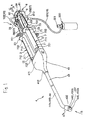
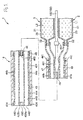
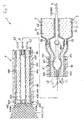
- Fig. 1 is a perspective view of a sprayer according to a first embodiment disclosed herein.
- Fig. 2 is a perspective view of the sprayer shown in Fig. 1 .
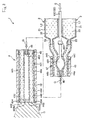
- Fig. 3 is a cross-sectional view of the sprayer taken along the section line A-A in Fig. 1 illustrating the opening/closing means of the sprayer (in the closed state of the gas passage).
- Fig. 4 is a cross-sectional view of the sprayer taken along the section line A-A in Fig. 1 illustrating the opening/closing means of the sprayer (in the opened state of the gas passage).
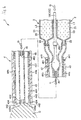
- Fig. 5 is a fragmentary longitudinal cross-sectional view of the nozzle and syringe of the sprayer shown in Fig. 1 , illustrating parts of the sprayer in one operational state.
- Fig. 6 is a fragmentary longitudinal cross-sectional view of the nozzle and syringe of the sprayer shown in Fig. 1 , illustrating parts of the sprayer in another operational state.
- Fig. 7 is a fragmentary longitudinal cross-sectional view of the nozzle and syringe of the sprayer shown in Fig. 1 , illustrating parts of the sprayer in another operational state.
- Fig. 8 is a fragmentary longitudinal cross-sectional view of the nozzle and syringe of the sprayer shown in Fig. 1 , illustrating parts of the sprayer in another operational state.
- Fig. 9 is a fragmentary longitudinal cross-sectional view of the nozzle and syringe of the sprayer shown in Fig. 1 , illustrating parts of the sprayer in another operational state.
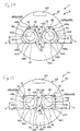
- Fig. 10 is a front view of the nozzle of the sprayer shown in Fig. 1 as viewed from the direction of the arrow B in Fig. 1 .
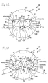
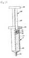
- Fig. 11 is a front view of a nozzle of a sprayer according to a second embodiment.
- Fig. 12 is a front view of a nozzle of a sprayer according to a third embodiment.
- Fig. 13 is a front view of a nozzle of a sprayer according to a fourth embodiment.
- Fig. 14 is a front view of a nozzle of a sprayer according to a fifth embodiment.
- Fig. 15 is a front view of a nozzle of a sprayer according to a sixth embodiment.
- Fig. 16 is a front view of a nozzle of a sprayer according to a seventh embodiment.
- Fig. 17 is a front view of a nozzle of a sprayer according to an eighth embodiment.
- Fig. 18 is a front view of a nozzle of a sprayer according to a ninth embodiment.
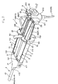
- Fig. 19 is a longitudinal cross-sectional view of a first syringe (the same as a second syringe) to be mounted on the sprayer shown in Fig. 1 .
- Figs. 1-10 illustrate one embodiment of the sprayer disclosed here
- Fig. 19 illustrates one of the two syringes to be mounted on the sprayer, it being understood that the other syringe is configured in the same way as that illustrated in Fig. 9
- the left and right sides are respectively referred to as the "front” and “rear (base)” in Figs. 1 , 2 and 5-9
- the lower and upper sides are respectively referred to as the "front” and “rear (base)” in Fig. 19
- the upper and lower sides are respectively referred to as “upper” or “forward upper” and “lower” or “forward lower” in Figs. 1-4 .
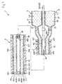
- the sprayer 1 disclosed here is used to mix together two liquids (first liquid L1 and second liquid L2), different in composition from one another, and apply the resulting mixed liquid or composition.
- the sprayer 1 is used with a first liquid-containing tube 2 (first syringe), forming a liquid supply means, and a second liquid-containing tube 3 (second syringe) forming a liquid supply means.
- first syringe 2 and the second syringe 3 are mounted and contain the first liquid L1 and the second liquid L2, respectively.
- a liquid (first liquid) L1 is filled in a space (reservoir space) 20 enclosed by an outer shell 21 and a gasket 24 prior to being mounted on the sprayer 1.
- the second liquid L2 is filled in the corresponding space 20 of the second syringe 3.
- the first liquid L1 to be filled in the first syringe 2 and the second liquid L2 to be filled in the second syringe 3 are different in their compositions (ingredients) from one another.
- the first and second liquids L1, L2 are suitably selected in accordance with the application and use or purpose of the sprayer 1, the condition being treated, etc.
- first and second liquids L1, L2 may contain carboxymethy dextrin modified with succinimidyl while the other may contain disodium hydrogenphosphate.
- first and second liquids L1, L2 are not limited to those just mentioned or otherwise described.
- the first and second liquids L1, L2 are supplied respectively to first and second inner tubes 44a, 44b of a nozzle 4, discussed in more detail below, with relative easiness and positiveness.
- the respective plungers 26 are pushed manually by the operator of the sprayer 1. Consequently, the operator is allowed to apply a liquid mixture in his/her desirable timing.
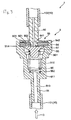
- the sprayer 1, mounted with the first and second syringes 2, 3 respectively filled with the first and second liquids L1, L2, includes a sprayer body 7, the nozzle 4, a manipulator 8, a valve mechanism 9 serving as an opening/closing means, and a gas tube (gas passage) 10 connected to a gas-containing canister or container 300 serving as a gas supply means for supplying gas.
- the gas-containing canister 300 is first explained prior to describing various parts constituting the sprayer 1.
- the gas-containing canister 300 contains or is filled with sterile gas G (hereinafter referred to as "gas G") under pressure (compressed) within the interior space thereof so that gas G can be supplied to the sprayer 1, more specifically the nozzle 4 of the sprayer 1.
- gas G sterile gas G
- the gas-containing canister 300 is arranged with an opening-and-closing valve (cock) 301 that opens and closes to control the supply/non-supply of gas G to sprayer 1. When using the sprayer 1, the valve 301 is opened.
- the type of gas G in the gas-containing canister 300 is not especially limited, but may be carbon dioxide, for example.
- the sprayer body 7 is configured to receive the syringes 2, 3 and position them in side-by-side relation (in parallel) to one another.
- the sprayer body 7 includes a base 71, a front plate (first engager) 72 provided in the front of the base 71, a rear plate (second engager) 73 provided in the rear of the base 71, and two handles 751, 752 provided in the vicinity of the rear plate 73 of the base 71.
- the base 71 is provided with receiving areas that are configured to receive the syringes.
- the receiving areas are in the form of recesses or concave regions 711, 712 that are semicircular in cross-section and arranged side-by-side in the upper portion of the base.
- the first syringe 2 i.e., the outer shell 21 of the first syringe 2
- the second syringe 3 i.e., the outer shell 21 of the second syringe 3
- the front plate 72 is provided at the front of the base 71.
- the front plate 72 includes grooves 721, 722 in positions respectively corresponding to the recesses 711, 712.
- Each of the first and second syringes 2, 3 possesses a diameter-reduced portion 22 at its forward end.
- the diameter-reduced portion 22 of the first syringe 2 is received in the groove 721, while the diameter-reduced portion 22 of the second syringe 3 is received in the groove 722.
- a rear plate 73 is provided at the rear of the base 71.
- the rear plate 73 is formed with recesses 731, 732 at positions respectively corresponding to the recesses 711, 712 of the base 71.
- the first and second syringes 2, 3 are positively fixed side by side in the sprayer body 7 by engaging the diameter-reduced portions 22 with the front plate 72 and by engaging the flanges 23 with the rear plate 73.
- the two handles 751, 752 are provided in the vicinity of the rear plate of the base 71.
- the handles 751, 752 are configured in a manner allowing the operator to put his/her fingers thereon during use of the sprayer 1.
- One of the handles 751 is constructed as an upwardly protruding or extending plate piece, while the other handle 752 is constructed as a downwardly extending or protruding plate piece.
- the front surface of each handle 751, 752 which faces to the front is arcuate in shaped, possessing a curved convex form.
- Various parts constituting the sprayer body 7 may be formed integrally or may be constructed separately one from another.
- the material of which the sprayer body 7 is formed is not particularly limited. Examples of suitable materials include a metallic material, e.g. aluminum or stainless steel, or plastic. The metallic and plastic materials can be used individually or in combination.
- a manipulator 8 is arranged in the rear of the sprayer body 7 and is movable in the longitudinal direction relative to the sprayer body 7.
- the manipulator 8 is a part that pushes the plungers 26, 26 of the first and second syringes 2, 3 in the forward direction toward the front (i.e., in the direction of the arrow C in Figs. 1 , 2 and 4 ).
- the manipulator 8 includes a coupler 81 that couples together the flanges 29 of the plungers 26 of the first and second syringes 2, 3, a presser 82 located rearwardly of the coupler 81, and a rail 83 extending from the coupler 81 toward the front.
- the coupler 81 is provided with recesses 811, 812 which both open upwardly.
- the recess 811 is in a form corresponding to the flange 29 of the plunger 26 of the first syringe 2 so that such flange 29 can be engaged therewith as shown in Fig. 2 .
- the other recess 812 is in a form corresponding to the flange 29 of the plunger 26 of the second syringe 3 so that the flange 29 of the plunger 26 of the second syringe 3 can be engaged therewith as seen in Fig. 2 .
- the coupler 81 is provided with a cylindrical portion 813 forming a cylinder located between the one recess 811 and the other recess 812.
- the cylindrical portion 813 is positioned such that the axis of the cylindrical portion 813 is vertically oriented or is parallel with the vertical direction as shown in Figs. 1 and 2 .
- the cylindrical portion 813 receives the valve means 9.
- the elongate rail 83 extends from the outer periphery of the cylindrical portion 813 of the coupler 81 in the forward direction (i.e., towards the front).
- the rail 83 is provided in the base 71 of the sprayer body 7 and is inserted or positioned in the guide 713 formed in an elongate form. By pushing the manipulator 8 in the direction of the arrow C, the rail 83 is guided along the guide 713. This allows for a relatively smooth pushing operation.
- a plate-like pusher 82 is provided at the rear of the cylindrical portion 813 of the coupler 81.
- the plate-like pusher 82 is adapted to move lengthwise of the sprayer body 7.
- the pusher 82 is a part pressed by the operator during use of the sprayer 1, i.e. upon applying a mixed liquid to a treatment region, diseased region, etc.
- the user's index finger is put on the handle 751
- the middle finger is placed on the handle 752 and the thumb is put on the pusher 82.
- the manipulator 8 pushher 82
- the manipulator 8 can be operated with smoothness and positiveness, thus improving the operability of the sprayer 1.
- the pusher 82 is coupled to a second connecting portion 92 of the valve means 9, discussed in more detail below.
- the material forming the manipulator 8 is not limited to a particular material. Examples include materials such as those listed in the explanation of materials which can be employed in the application body 7.
- valve means 9 is provided in cylindrical portion 813 of manipulator 8.
- the valve means 9 operates to open and close the gas G flow from the gas-containing canister 300 to the nozzle 4.
- the first tube 101 and the second tube 102 are shut off as seen in Fig. 3 and communicated together as seen in Fig. 4 by the operation of the valve means 9.
- the valve means 9 has a first connecting portion 91 connected to the first tube 141, a second connecting portion 92 connected to the second tube 102, and an openable and closable valve 93 received in the first connecting portion 91.
- the first connecting portion 91 is tubular in form and includes a lumen.
- the lumen of the first connecting portion 91 includes a container portion 912 (larger-diameter portion), located on the downstream side, and the valve 93.
- the lumen of the first connecting portion 91 also includes a diameter-reduced portion 913 having a diameter smaller than the inner diameter of the container portion 912 on the upstream side.
- a step 911 whose inner diameter sharply changes, is formed at the boundary between the diameter-reduced portion 913 and the container portion 912.
- the second connecting portion 92 is tubular in form. As mentioned before, the second connecting portion 92 is coupled to the pusher 82 of the manipulator 8.
- the second connecting portion 92 whose lower end 921 is supported by the seal member 94 of the valve 93 (i.e., the lower end of the second connecting portion is received in a hole in the seal member 94), is arranged downstream of the first connecting portion 91 through the seal member 94.
- the second connecting portion 92 is arranged to be displaced between a first position (i.e., the state shown in Fig.
- the seal member 94 of the valve 93 is constructed as an elastic material.
- the valve 93 includes the seal member 94, a flange 95 positioned upstream of the seal member 94, and a bias member 96 that biases the flange 95 toward the seal member 94.
- the seal member 94 is in a link form, and has an inner periphery 941 in close contact with the outer periphery 922 of the lower end 921 of the second connecting portion 92.
- the seal member 94 has an outer periphery 942 in close contact with the inner periphery 914 of the container 912 of the first connecting portion 91.
- the flange 95 has an outer diameter greater than the outer diameter of the second connecting portion 92.
- the flange 95 is arranged oppositely to (in facing relation to) a lower end surface of the second connecting portion 92 through gap 97.
- the bias member 96 is a compression coiled spring. In the compressed state, its upper end 961 is in abutment against the flange 95 while the lower end 962 is in abutment against the step 911. This can positively bias the flange 95 toward the seal member 94.
- the flange 95 is biased by the bias member 96 and placed in hermetic contact with the seal member 94 as shown in Fig. 3 when the second connecting portion 92 is in a first position, i.e. when no external force is applied to the second connecting portion 92. This places the valve 93 in the closed state.
- valve 93 is allowed to positively open and close interactively with the pressing of the manipulator 8.
- the valve 93 is in the closed state, the gas G is positively shut off from flowing from the gas-containing canister 300 to the nozzle 4.
- the valve 93 is in the open state, the gas G can be positively released to flow.
- the material forming the first connecting portion 91, the second connecting portion 92, the flange 95 and the bias member 96 is not limited, but can include, for example, metal material or plastic, either individually or in combination.
- the material forming the seal member 94 is also not limited to a specific material.
- suitable materials include rubber material of various types, e.g. natural or butyl rubber.
- the nozzle 4 is arranged on the front plate 72 of the sprayer body 72.
- the nozzle 4 ejects or sprays the gas G passing through the tube 10, the first liquid L1 passing through the diameter-reduced portion 22 of the first syringe 2, and the second liquid L2 passing through the diameter-reduced portion 22 of the second syringe 3.
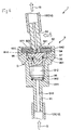
- the nozzle 4 includes a first inner tube 44a connected to the diameter-reduced portion 22 of the first syringe 2 and through which the first liquid L1 is allowed to pass, a second inner tube 44b connected to the diameter-reduced portion 22 of the second syringe 3 and through which the second liquid L2 is allowed to pass, an outer tube 43 in which the first and second inner tubes 44a, 44b are received or positioned, a supply tube 46 connected to the second tube 102 and adapted to supply gas G to the interior of the outer tube 43, and a fixing member 41 (shown in Fig. 1 ) that fixes the nozzle 4 to the front plate 72 of the sprayer body 7.
- the first tube 44a, the second tube 44b, the outer tube 43 and the supply tube 46 may be each structured of a rigid material, a non-rigid material, a resilient material or the like, having flexibility.
- the material forming the second tube 44b, the outer tube 43 and the supply tube 46 is a flexible material.
- the material of first inner tube 44a is, for example, a non-rigid or rigid resin of various types, e.g. polyvinyl chloride, polyethylene or polypropylene, a rubber material in various types, e.g. natural rubber, butyl rubber or silicone rubber, or stainless steel or aluminum.
- the first inner tube 44a and the second inner tube 44b are similar in structure and so the following explanation pertaining to the first inner tube 44a applies equally to the second inner tube 44b.
- the first inner tube 44a is constructed as an elongate tubular member, whose base is connected to the diameter-reduced portion 22 of first syringe 2.
- the first inner tube 44a has a liquid orifice 442 that opens at the tip of the tube 44a.
- the liquid orifice 442 is a part through which the first liquid L1 is ejected (sprayed) that is issued out of the diameter-reduced portion 22 of the first syringe 2 when the plunger 26 of the first syringe 2 is pushed.
- the first inner tube 44a is circular in cross-section at its inner periphery (inner peripheral surface) 443 and its outer periphery (outer peripheral surface) 444. Accordingly, the liquid orifice 442 is also circular in form at its inner periphery 443 and outer periphery 444 as shown in Fig. 10 .
- the liquid orifice 442 possesses a tube wall thickness that is circumferentially constant. As a result, the liquid orifice 442 is positioned concentric relative to the inner periphery 443 and outer periphery 444 of the tube 44a. As mentioned the second inner tube 44b is the same in structure to the first inner tube 44a.
- the supply tube 46 is also received or positioned in the outer tube 43 as shown in Figs. 5-9 ).
- the supply tube 46 is an elongate tubular member having a base 462 connected to the second tube 102.
- the base 462 is located between the respective bases of the first and second inner tubes 44a, 44b arranged side-by-side.
- the supply tube 46 has a tip 463 positioned at an intermediate point of the outer tube 43. Gas G is ejected at the tip 463, thereby supplying gas G to the interior of the outer tube 43.
- the tip 463 of the supply tube 46 is fixed in a liquid-tight manner with the outer peripheries of the first and second tubes 44a, 44b at a fixed portion, and the inner peripheral surface 431 of the outer tube 43 is fixed in a liquid-tight manner through a fixed portion 48 to the outer peripheries of the first and second tubes 44a, 44b.
- the material forming the fixed portion 48 is not especially limited. Examples of suitable materials are those materials mentioned above in connection with the seal member 94.
- the first inner tube 44a, the second inner tube 44b and the supply tube 46 are collectively received in the outer tube 43.
- the outer tube 43 is an elongate tubular member having a base connected to the front opening 412 of fixed member 41.
- the tip 463 of the supply tube 46 is positioned at an intermediate point of the outer tube 43 (i.e., an intermediate point considered with reference to the longitudinal extent of the outer tube 43) so that the gas G can be supplied to the interior of the outer tube 43 through the tip 463.
- the supplied gas G is able to pass or flow through the gaps between the outer tube 43, the first inner tube 44a and the second inner tube 44b.
- the tip of the outer tube 43 includes a front wall 432.
- a gas orifice 436 (better shown in Fig. 10 ) constructed as two lumens 433a, 433b opens in the front wall 432.
- the two lumens 433a, 433b (gas orifice 436) are parts through which the gas G supplied from the supply pipe 46 is ejected (sprayed).
- the lumens 433a, 433b each possess a (regular) triangular shape (cross-sectional shape) so that the inner periphery of the lumens 433a, 433b possesses a triangular shape (regular triangular shape) with rounded corners.
- the lumen 433a possessing this shape has a distance (length) H, between the center 435 of the lumen and the side (preferably the midpoint of the side), that is equal to or somewhat smaller than the radius R of the outer periphery 444 of the liquid orifice 442 of the first inner tube 44a.
- the liquid orifice 442 of the first inner tube 44a is arranged in the interior of and concentrically to the lumen 433a, while the liquid orifice 442 of the second inner tube 44b is arranged in the interior of and concentrically to the lumen 433b. Because the positional relationship between the lumen 433a and the liquid orifice 442 of the first inner tube 44a is the same as the positional relationship between the lumen 433b and the liquid orifice 442 of the second inner tube 44b, the explanation of the positional relationship between the lumen 433a and the liquid orifice 442 of the first inner tube 44a applies equally to the positional relationship between the lumen 433b and the liquid orifice 442 of the second inner tube 44b.
- contact is provided at multiple points 45 (three points in this illustrated embodiment) between the inner periphery 434 of the lumen 433a and the outer periphery 444 of the liquid orifice 442 of the first inner tube 44a.
- the liquid orifice 442 is positively restricted from deviating radially (i.e., radially shifting), for example under the pressure of the gas G.
- the liquid orifice 442 is positively fixed relative to the lumen 433a (gas orifice 436).
- the gas G can be positively ejected in a uniform manner through the gaps 42. This allows the positive atomization and ejection (spraying) of the first liquid L1.
- the multiple (three) points of contact 45 are spaced apart at equal angular intervals about the center 435 (about the first inner tube 44a). This makes it possible to establish gaps 42 that are equal in dimension. Accordingly, gas G can be ejected uniformly in the direction surrounding the first liquid L1 being ejected (circumferentially of the liquid orifice 442). This allows further positive atomization of the first liquid L1
- the maximum width W of the gaps 42 is not especially limited, but is preferably 20 - 200 ⁇ m, more preferably 40 - 80 ⁇ m, where the sprayer 1 is used in laparoscopic surgery.
- the radius R of the outer periphery 444 of each liquid orifice 442 is not limited to a particular dimension.
- the Radius R of the outer periphery 444 of each liquid orifice 442 is 0.2 - 1 mm, more preferably 0.4 - 0.8 mm, where the sprayer 1 is used in a laparoscopic surgery.
- the outer tube 43 having the lumens 433a, 433b, the first inner tube 44a having the liquid orifice 442 and the second inner tube 44b having the liquid orifice 442 are first prepared or obtained.
- the distance H concerning lumen 433a (true for lumen 433b) is established nearly equal to or somewhat smaller than the radius R of liquid orifice 442.
- the first inner tube 44a is inserted in the outer tube 43 at the base thereof, to fit the lumen 433a with the liquid orifice 442. This places the lumen 433a and the liquid orifice 442 in multi-point contact (three point contact in this illustrated embodiment).
- the second inner tube 44b is inserted in the outer tube 43 at the base thereof, to fit the lumen 433b with the liquid orifice 442. This places the lumen 433b and outer periphery 444 of liquid orifice 442 in multi-point contact (three point contact in this illustrated embodiment). It is thus possible to relatively easily manufacture the nozzle 4 so that it can eject gas relatively uniformly in a manner as mentioned before.
- Fig. 10 provides point contacts between the inner periphery of the lumen 433a (as well as the lumen 433b) and the outer periphery 444 of the liquid orifice 442.
- the embodiment shown in Fig. 10 provides the liquid orifice 442 of the first inner tube 44a and the liquid orifice 442 of the second inner tube 44b of the same size, and the lumen 433a and the lumen 433b of the same size correspondingly. Because the sprayer 1 is formed with respective lumens 433a, 433b corresponding to the liquid orifices 442, 442 of the first and second inner tubes 44a, 44b, the liquid orifices 442, 442 of the first and second inner tubes 44a, 44b can be made different in size from each other, depending upon, for example, the liquid mixture to be applied to the diseased or treatment region.
- the liquid orifices 442, 442 of the first and second inner tubes 44a, 44b can be made different in size from each other, depending upon, for example, the nature or types of first and second liquids L1, L2 used.
- the lumens 433a, 433b can be properly changed in size.
- the nozzle 4 is preferably made in a curved (bent) shape at its tip, as required, as shown in Fig. 1 . This makes it possible to relatively easily insert the tip of nozzle 4 into a lumen where the sprayer 1 is used in laparoscopic surgery.
- a marker 437 is provided in the outer surface of the nozzle 4 (the outer tube 43) to permit visual recognition of the juxtaposing direction of the two liquid orifices 442. This makes it possible to carry out application while confirming the juxtaposing direction of two liquid orifices 442 where using the sprayer 1.
- Figs. 5-9 illustrate a volume changer 441 provided respectively at each of the first and second inner tubes 44a, 44b at positions close to the sprayer body 7 to change the interior volumes of the first and second inner tubes 44a, 44b.
- the volume changer 441 of the first inner tube 44a is constituted by a volume changing portion of the first inner tube 44a
- the volume changer 441 of the second inner tube 44a is constituted by a volume changing portion of the second inner tube 44a.
- the volume changer 441 of the first inner tube 44a and the volume changer 441 of the second inner tube 44b are arranged in symmetric positions with respect to the supply tube 46.
- a balloon 461 is provided to expand and contract in response to the flow rate (supply amount) of the gas G.
- the balloon 461 is arranged in a longitudinal position corresponding to the longitudinal position of the volume changers 441.
- the balloon 461 is arranged, with respect to the radial direction, between the volume changer 441 of the first inner tube 44a and the volume changer 441 of the second inner tube 44b.
- the balloon 461 possesses a thickness (i.e., the thickness of the tube wall of the balloon 461) smaller than the thickness of the supply tube 46 on either longitudinal end of the balloon. This helps positively assure expansion upon supplying (flowing of) gas G in the balloon 461 and contraction upon stopping the supply of the gas G.
- the balloon 461 serves as a means for deforming the volume changers 441 in a manner increasing and decreasing the volumes of the volume changers 441 due to the expansion and contraction.
- the balloon 461 in its natural state has an outer diameter greater than the outer diameter of the portions of the supply tube 46 in front of and rearward of the balloon 461.
- the balloon 461 may contact the volume changers 441 in a manner not pressing the volume changers 441 (i.e., not reducing the volume of the volume changers 441) or may be spaced from the volume changers 441.
- the balloon 461 is in contact with the volume changers 441 in a manner that does not press the volume changers to an extent causing a reduction in volume. In this case, the volume changers 441 are maximal in volume.
- the term "natural state” refers to the state where no external forces are applied, i.e. gas G is not supplied in the interior thereof.
- the balloon 461 expands by virtue of being supplied with the gas.
- the expanded balloon 461 presses the volume changers 441 against the elastic force of the volume changers 441. This reduces the respective volumes of the volume changers 441 (volume changing portions of the inner tubes 44a, 44b).
- the expanded balloon 461 presses the volume changers 441 to reduce the volume of the volume changers, but not to such a degree that the inner surfaces of the volume changers 441 are brought into close contact with each other (i.e., a state where the volume changers are completely closed off).
- the volume changers 441 are released from being pressed.
- the volume changers 441 are thus restored in shape by their own elasticity as shown in Fig. 9 .
- the nozzle 4 has a ring (band) 47 holding the volume changers 441 of the respective first and second inner tubes 44a, 44b and the balloon 461 collectively from the outer tube.
- the ring 47 can be formed by winding a strip of plastic material, for example.
- the ring 47 restricts the positional relationship between the volume changers 441 and the balloon 461 irrespective of the expansion and contraction of balloon 461. Due to this, when the balloon 461 expands, the expanded balloon 461 positively presses the volume changers 441.
- the volume changers 441 positively change in volume in response to the expansion and contraction of the balloon 461.
- the fixing member 41 is arranged at the base of the nozzle 4.
- the fixing member 41 is a hollow member having a front opening 412 and a base opening 411.
- the front opening 412 is hermetically connected with the base of the outer tube 43 while the base opening 411 is secured to the front plate 72 of the sprayer body 7.
- Located in the interior of the fixing member 41 are a connecting portion of the first inner tube 44a with the first syringe 2, a connecting portion of the second inner tube 44b with the second syringe 3 and a connecting portion (base 462) of the supply tube 46 with tube 10. This can cover the connecting portions and hence protect those portions.
- the operation of the sprayer 1 is now described, considered with reference to a usable state of the sprayer in which it is loaded with the first and second syringes 2, 3 respectively filled with the first and second liquids L1, L2 and connected to the gas-containing canister 300.
- the first and second syringes 2, 3 are respectively filled with the first and second liquids L1, L2 in an amount required (sufficient) for application to a diseased or treatment region.
- the gas-containing canister 300 is opened at its valve 301 wherein gas G is to be supplied to sprayer 1.
- the force causing a gap 98 between the seal member 94 and the flange 95 which operates against the force of the bias member 96 urging the flange 95 on the seal member 94, i.e. the pressing force to incline the second connecting portion 92 in the direction of the arrow C from the first position into the second position, is established smaller than the force that moves the plungers 26 of the first and second syringes 2, 3 toward the front. Namely, before the movement of the plungers 26 occurs, the gap 98 arises to supply gas G.
- Such setting is available by properly establishing various conditions, for example, the spring constant of the bias member 96, the liquid viscosities of the liquids and the inner diameters of the outer shells 21.
- the user's index finger is put on the handle 751 of the sprayer body 7, the user's middle finger is put on the handle 752 and the user's thumb is placed on the presser 82 of the manipulator 8.
- the first liquid L1 is not supplied to the first passage 44
- the second liquid L2 is not supplied to the second passage 45
- the gas G is not supplied to the third passage 46 as shown in Fig. 5 . Due to this, the gas G and the first and second liquids L1, L2 are not ejected (sprayed) through the nozzle 4.
- the inflatable portion 461 is not expanded, the volume changers 441, 441 are not pressed by the inflatable portion.
- first and second liquids L1, L2 are not yet supplied respectively to the first and second inner tubes 44a, 44b.
- the second connecting portion 92 inclines into a limitation so that the pressing force of the thumb is delivered to the coupler 81 through the presser 82.
- the pushed out portion of the first liquid L1 passes through the volume changer 441 which remains pressed by the balloon 461 and moves toward the front, i.e. it reaches the liquid orifice 442 of the first inner tube 44a where it is ejected (sprayed) therefrom as shown in Fig. 7 .
- the second liquid L2 passes through the volume changer 441 which remains pressed by the balloon 461 in a manner similar to the first liquid L1 and reaches the liquid orifice 442 of the second inner tube 44b where it is ejected therefrom as shown in Fig. 7 .
- the first and second liquids L1, L2 thus ejected are entrained in the gas G ejected at a high rate. Due to this, the first and second liquids L1, L2 are atomized or turned into atomized sprays and mixed together, thus being applied to a diseased or treatment region.
- the liquid orifice 442 of the first inner tube 44a is fixed relative to the lumen 433a
- the liquid orifice 442 of the second inner tube 44b is fixed relative to the lumen 433b as mentioned before
- the gas G is sprayed uniformly. This makes it possible to positively atomize the first and second liquids L1, L2, thereby positively mixing the first and second liquids L1, L2 together and applying those to a diseased or treatment region.
- the manipulator 8 As the pressing force of the thumb on the presser 82 (manipulator 8) is reduced after the completion of a predetermined amount of application to the diseased or treatment region, the manipulator 8 in its entirety is stopped from moving. This stops the plungers 26 from moving and hence stops the first and second liquids L1, L2 from ejecting as seen in Fig. 8 . At this time, because the second connecting portion 92 is kept in a second position by the urging of the presser 82, the gas G continues to be ejected as shown in Fig. 8 .
- the balloon 461 contracts in the manner depicted in Fig. 9 .
- the first liquid L1 at the tip P1 of the liquid orifice 442 of the first inner tube 44a is retracted rearwardly
- the second liquid L2 at the tip P2 of the liquid orifice 442 of the second inner tube 44b is retracted rearwardly as seen in Fig. 9 .
- the first and second liquids L1, L2 can be prevented from being mixed together in the vicinity of the liquid orifices 442 of the first and second inner tubes 44a, 44b and can thus be prevented from forming a gelatinous form or mass in the vicinity of the liquid orifices 442 of the first and second inner tubes 44a, 44b.
- This helps positively prevent the clogging (adhesion of a solidified substance due to the mixing of the first and second liquids L1, L2 together) in the liquid orifices 442 of the first and second inner tubes 44a, 44b and the peripheral lumens 433a, 433b after the use of sprayer 1 (after the completion of application).
- the sprayer 1 in a state free from clogging can then be again used for the application to a diseased region.
- uniform ejection of the gas G is done, hence enabling the application of a liquid mixture in which the first and second liquids L1, L2 are uniformly mixed together.
- the sprayer 1 is constructed to eject (spray) gas G in advance of the first and second liquids L1, L2 through the nozzle 4. This can help prevent the first and second liquids L1, L2 solely from being ejected and applied to a diseased or treatment region.
- the first and second liquids L1, L2 are both positively sprayed in atomized forms. Hence, those liquids are positively mixed together.
- the sprayer 1 is also constructed to stop the gas G from ejecting later in timing than the first and second liquids L1, L2 (i.e., the gas ejection stops after the ejection of the liquids L1, L2 ends). Due to this, where liquids remains at the orifices because of stopping the liquids from ejecting, the remaining liquid can be blown away by the gas G. Therefore, it is possible to more positively prevent the trouble (e.g., clogging resulting from solidification) caused by the reaction of the first and second liquids L1, L2 at the liquid orifices 442 of the first and second inner tubes 44a, 44b and the peripheral lumens 433a, 433b.
- the trouble e.g., clogging resulting from solidification
- Sprayer 1 in a state free from clogging can be again used for the application to a diseased region.
- the gas G is ejected uniformly, hence applying a liquid mixture in which the first liquid L1 and the second liquid L2 are uniformly mixed together.
- Fig. 11 illustrates a second embodiment of a nozzle of a sprayer disclosed here.
- the following description primarily describes aspects of the sprayer that differ from the foregoing embodiment.
- Features of this embodiment that are the same as those described above are identified by the same reference numeral and a detailed description of such features is not repeated.
- the present embodiment is similar to the first embodiment, except that the gas orifice has a different form.
- the nozzle 4A has two lumens 433a, 433b whose inner peripheries 434 each possess a square shape or form. Because the inner peripheries 434 of the two lumens 433a, 433b are the same, the following explanation describes one of the lumens 433a and the associated liquid orifice 442 of the first inner tube 44a arranged inside the lumen 433a.
- Contact between the inner periphery 434 of the lumen 433a and the outer periphery 444 of the liquid orifice 442 of the first inner tube 44a is provided at four points 45.
- Those contact points 45 are circumferentially spaced apart at equal angular intervals about the center 435.
- a space exists between the outer periphery of the liquid orifice 442 and the inner periphery of the lumen 433a (gas orifice) at regions between circumferentially adjacent contact points 45.
- the number of contact points in this embodiment is greater than that of the arrangement of the lumen 433a and the liquid orifice 442 of the first embodiment.
- the liquid orifice 442 is fixed more positively to the lumen 433a.
- gas G can be ejected (sprayed) further uniformly.
- the gas G is can be ejected positively and uniformly through four gaps 42, thereby ejecting the first liquid L1 with positive atomization.
- the gas G can be ejected positively and uniformly also at the lumen 433b through the four gaps 42, thereby ejecting the second liquid L2 with positive atomization.
- the atomized first liquid L1 and the atomized second liquid L2 are positively mixed together.
- Fig. 12 illustrates a third embodiment of a nozzle of a sprayer disclosed here.
- the following description primarily describes aspects of the sprayer that differ from the foregoing embodiments. Features of this embodiment that are the same as those described above are identified by the same reference numeral and a detailed description of such features is not repeated.
- the present embodiment is similar to the second embodiment, except that the gas orifice has a different form.
- the nozzle 4B of the sprayer 1B shown in Fig. 12 has lumens 433a, 433b whose inner peripheries 434 each possess a square shape or form, with rounded corners.
- the maximum width W of the gaps 42 is smaller than the maximum width W of the gaps 42 of the second embodiment, thus increasing the flow speed of the gas G ejected (sprayed) through the gaps 42. This helps contribute to a positive atomization of the liquid mixture (liquid) with a smaller amount of gas.
- Fig. 13 illustrates a fourth embodiment of a nozzle of a sprayer disclosed here.
- the following description primarily describes aspects of the fourth embodiment that differ from the foregoing embodiments.
- Features of this embodiment that are the same as those described above are identified by the same reference numeral and a detailed description of such features is not repeated.
- the present embodiment is similar to the first embodiment, except that the gas orifice has a different form.
- the sprayer 1C shown in Fig. 13 includes the nozzle 4C having lumens 433a, 433b whose inner peripheries 434 each possess a regular pentagonal shape or form. Because the inner peripheries 434 of both lumens 433a, 433b are of the same form, the following explanation will describe the lumen 433a and the liquid orifice 442 of the first inner tube 44a arranged inside the inner lumen 433a, and such description applies to the lumen 433b and the liquid orifice 442 of the second inner tube 44b.
- contact 45 between the inner periphery 434 of the lumen 433a and the outer periphery 444 of the liquid orifice 442 of the first inner tube 44a is provided at five contact points.
- Those five contact points 45 are circumferentially spaced apart at equal angular intervals about the center 435.
- a space or gap exists between the outer periphery of the liquid orifice 442 and the inner periphery of the lumen 433a (gas orifice) at regions between the circumferentially adjacent contact points 45.
- the liquid orifice 442 is fixed more positively to the lumen 433a. This helps ensure a positive and uniform ejection (spraying) of the gas G through five gaps 42, thereby ejecting the first liquid L1 with a positive atomization.
- the lumen 433b is also allowed to positively and uniformly eject the gas G through five gaps 42, thereby positively ejecting the second liquid L2 with a positive atomization.
- the atomized first liquid L1 and the atomized second liquid L2 are mixed positively.
- Fig. 14 illustrates a fifth embodiment of a nozzle of a sprayer disclosed here.
- the following description primarily describes aspects of the fifth embodiment that differ from the foregoing embodiments.
- Features of this embodiment that are the same as those described above are identified by the same reference numeral and a detailed description of such features is not repeated.
- This fifth embodiment is similar to the first embodiment, except that the gas orifice has a different form.
- the nozzle 4D has two lumens 433a, 433b whose inner peripheries 434 each possess a regular hexagonal form or shape. Because the inner peripheries 434 of both the lumens 433a, 433b possess the same shape or form , the following explanation about the lumen 433a and the liquid orifice 442 of the first inner tube 44a arranged inside the lumen 433a applies equally to the other lumen 433b and the liquid orifice 442 of the second inner tube 44b arranged inside the lumen 433b.
- contact is provided at six contact points 45 between the inner periphery 434 of the lumen 433a and the outer periphery 444 of the liquid orifice 442 of the first inner tube 44a.
- Those contact points 45 are spaced apart at equal angular intervals about the center 435.
- a space or gap exists between the outer periphery of the liquid orifice 442 and the inner periphery of the lumen 433a (gas orifice) at regions between the circumferentially adjacent contact points 45.
- the liquid orifice 442 is fixed more positively to the lumen 433a. This helps ensure that the gas G is positively and uniformly ejected (sprayed) through the six gaps 42, thereby ejecting the first liquid L1 with a positive atomization.
- the lumen 433b also ejects gas G positively and uniformly through the six gaps 42, thereby ejecting the second liquid L2 with a positive atomization.
- the atomized first liquid L1 and the atomized second liquid L2 are positively mixed together.
- Fig. 15 illustrates a sixth embodiment of a nozzle of a sprayer disclosed here.
- the following description primarily describes aspects of the sixth embodiment that differ from the foregoing embodiments.
- Features of this embodiment that are the same as those described above are identified by the same reference numeral and a detailed description of such features is not repeated.
- the sixth embodiment is similar to the first embodiment, except that the gas orifice and the liquid orifice respectively have different forms.
- the nozzle 4E has the first inner tube 44a and the second inner tube 44b in which the outer peripheries 444 of the liquid orifice 442 each possess a square shape or form, rounded at the corners as illustrated.
- the lumens 433a, 433b have respective inner peripheries 434 that are each circular in shape or form.
- the lumen 433a (the same as the lumen 433b) possessing such a form has an inner periphery 434 whose radius R is established nearly equal to or somewhat smaller than the distance (length) H between the center 435 of the liquid orifice 442 and each side.
- the four contacts 45 are spaced apart at equal angular intervals about center 435. This makes it possible to establish gaps 42 equal in size to one another between circumferentially adjacent contact points, thereby uniformly ejecting gas G in the direction surrounding the first liquid L1 being ejected. Consequently, the first liquid L1 is positively atomized.
- each liquid orifice 442 is in a square form (shape) with rounded corners, it is not limitative but may be in a square form.
- Fig. 16 illustrates a seventh embodiment of a nozzle of a sprayer disclosed here.
- the following description primarily describes aspects of the seventh embodiment that differ from the foregoing embodiments.
- Features of this embodiment that are the same as those described above are identified by the same reference numeral and a detailed description of such features is not repeated.
- This seventh embodiment is similar to the sixth embodiment, except that the liquid orifice has a different form or shape.
- the nozzle 4F has the liquid orifices 442 whose outer peripheries 444 (also true for the inner peripheries 443) each possess a regular pentagonal form or shape. Because the outer periphery 444 of the liquid orifice 442 of the first inner tube 44a and the outer periphery 444 of the liquid orifice 442 of the second inner tube 44b are the same in shape or form, the following description of the liquid orifice 442 of the first inner tube 44a and the lumen 433a applies equally to the liquid orifice 442 of the second inner tube 44b and the lumen 433b.
- contact between the outer periphery 444 of the liquid orifice 442 of the first inner tube 44a and the inner periphery 434 of the lumen 433a exists at five points 45. Those contact points 45 are spaced apart at equal angular intervals about the center 435. A space or gap exists between the outer periphery of the liquid orifice 442 and the inner periphery of the lumen 433a (gas orifice) at regions between the circumferentially adjacent contact points 45.
- the number of contact points in this embodiment is greater than the number of contact points of the liquid orifice 442 and lumen 433a in the sixth embodiment by virtue of the configuration of the liquid orifice 442 and the lumen 433a.
- the liquid orifice 442 is fixed more positively relative to the lumen 433a.
- Fig. 17 depicts an eighth embodiment of a nozzle of a sprayer disclosed here.
- the following description primarily describes aspects of the eighth embodiment that differ from the foregoing embodiments.
- Features of this embodiment that are the same as those described above are identified by the same reference numeral and a detailed description of such features is not repeated.
- the sprayer 1 G includes a nozzle 4G having a gas orifice 436 possessing a single (one) lumen 433c.
- the liquid orifice 442 of the first inner tube 44a and the liquid orifice 442 of the second inner tube 44b are arranged collectively inside the lumen 433c.
- the lumen 433c has an inner periphery 434 possessing a rectangular form or shape, with a longer side of length M1 established equal to or somewhat smaller than two times the radius R of the outer periphery of one orifice 442 plus two times the radius R of the outer periphery of the other orifice 442.
- the length of the longer side M1 is equal to or somewhat smaller than R x 4.
- the liquid orifices 442, arranged inside the lumen 433c, have outer peripheries 444 contacting the inner periphery 434 of the lumen 433c at three points 45. Meanwhile, the outer peripheries 444 of the liquid orifices 442 are in point-contact with each other at one point. A space or gap exists between the outer periphery of the liquid orifice 442 and the inner periphery of the lumen 433a (gas orifice) at regions between the circumferentially adjacent contact points 45.
- the liquid orifices 442 are positively fixed relative to the lumen 433c (gas orifice 436).
- the spacing (pitch) between the liquid orifices 442 is smaller than that of the first embodiment. Due to this, when the first and second liquids L1, L2 are ejected, the liquids are mixed together further positively.
- the structure of the nozzle 4G is simplified because the two inner tubes (the first inner tube 44a and the second inner tube 44b) are arranged in a single (only one) lumen 433c.
- This relatively simple structure allows the first and second inner tubes 44a, 44b to be comparatively accurate in position relative to the lumen 433c.
- the inner periphery 434 of the lumen 433c is not limited to being rectangular in shape, but may be octagonal in shape in which two regular pentagons share their one sides, for example.
- Fig. 18 depicts a ninth embodiment of a nozzle of a sprayer disclosed here.
- the following description primarily describes aspects of the ninth embodiment that differ from the foregoing embodiments.
- Features of this embodiment that are the same as those described above are identified by the same reference numeral and a detailed description of such features is not repeated.
- the liquid orifice has a different form.
- the nozzle 4H of the sprayer 1 H includes chords 445 (longitudinally extending flat surface portions) that are respectively formed in the outer peripheries 444 of the liquid orifices 442, wherein the chords 445 are in abutment against each other. Due to this, two liquid orifices 442 are in line-contact with each other at the outer peripheries 444 thereof, rather than point-contact.
- the spacing (pitch) of both liquid orifices 442 can be reduced compared to the spacing in the eighth embodiment. Due to this, when the first and second liquids L1, L2 are ejected, the liquids can be mixed together further positively.
- the structure of nozzle 4H can be simplified because two inner tubes (first inner tube 44a and second inner tube 44b) are arranged in a single (only one) lumen 433c in a manner similar to the eighth embodiment.
- first and second inner tubes 44a, 44b are comparatively accurately positioned relative to lumen 433c.
- chords (flat surface portions) 445 of the respective liquid orifices 442 are not limited to being in abutment, but may be bonded together (e.g., by way of an adhesive or solvent) for example.
- the sprayer disclosed here has been described based on the illustrated embodiments, but the invention is not limited to such embodiments. Various parts constituting the sprayer can be replaced with alternatives that exhibit the same or similar/equivalent functions. Additional features can also be added. Also, the sprayer may be a combination of two or more structures (features) of the foregoing embodiments.
- the sprayer is assembled by loading the two syringes thereon so that two types of liquids different in liquid composition can be ejected with mixing from the syringes.
- this is not limitative as one syringe may be structurally loaded so that one type of liquid can be ejected from the syringe.
Landscapes
- Chemical Kinetics & Catalysis (AREA)
- Health & Medical Sciences (AREA)
- Chemical & Material Sciences (AREA)
- Life Sciences & Earth Sciences (AREA)
- Surgery (AREA)
- Heart & Thoracic Surgery (AREA)
- Engineering & Computer Science (AREA)
- Biomedical Technology (AREA)
- Nuclear Medicine, Radiotherapy & Molecular Imaging (AREA)
- Medical Informatics (AREA)
- Molecular Biology (AREA)
- Animal Behavior & Ethology (AREA)
- General Health & Medical Sciences (AREA)
- Public Health (AREA)
- Veterinary Medicine (AREA)
- Nozzles (AREA)
- Media Introduction/Drainage Providing Device (AREA)
Applications Claiming Priority (1)
| Application Number | Priority Date | Filing Date | Title |
|---|---|---|---|
| JP2007137119A JP2008289986A (ja) | 2007-05-23 | 2007-05-23 | 塗布具 |
Publications (2)
| Publication Number | Publication Date |
|---|---|
| EP2000215A2 true EP2000215A2 (de) | 2008-12-10 |
| EP2000215A3 EP2000215A3 (de) | 2011-03-09 |
Family
ID=39590799
Family Applications (1)
| Application Number | Title | Priority Date | Filing Date |
|---|---|---|---|
| EP08156518A Withdrawn EP2000215A3 (de) | 2007-05-23 | 2008-05-20 | Sprühvorrichtung |
Country Status (3)
| Country | Link |
|---|---|
| US (1) | US7846125B2 (de) |
| EP (1) | EP2000215A3 (de) |
| JP (1) | JP2008289986A (de) |
Cited By (4)
| Publication number | Priority date | Publication date | Assignee | Title |
|---|---|---|---|---|
| WO2010078439A1 (en) | 2008-12-30 | 2010-07-08 | Baxter International Inc. | Tissue sealing system and apparatus |
| WO2013171029A1 (de) | 2012-05-14 | 2013-11-21 | Sulzer Mixpac Ag | Mehrkomponentenkartusche, austraggerät für eine mehrkomponentenkartusche und system zum mischen und sprühen von fliessfähigen komponenten |
| WO2014149665A1 (en) * | 2013-03-15 | 2014-09-25 | Ethicon, Inc. | Device and system for dispensing a biological sealant |
| EP2695626B1 (de) * | 2012-08-10 | 2018-10-31 | Nordson Corporation | Vorrichtung zum Entladen einer reaktiven Flüssigkeit |
Families Citing this family (10)
| Publication number | Priority date | Publication date | Assignee | Title |
|---|---|---|---|---|
| JP5222591B2 (ja) * | 2008-03-12 | 2013-06-26 | テルモ株式会社 | 塗布具 |
| JP5255387B2 (ja) * | 2008-09-25 | 2013-08-07 | テルモ株式会社 | 塗布具 |
| JP5620387B2 (ja) | 2009-09-02 | 2014-11-05 | テルモ株式会社 | 多孔質構造体 |
| TWM391396U (en) * | 2010-05-17 | 2010-11-01 | Dermato Plastica Beauty Dpb Co Ltd | Injection device |
| USD726304S1 (en) * | 2012-03-22 | 2015-04-07 | Terumo Kabushiki Kaisha | Medicament sprayer |
| US9738730B2 (en) | 2013-02-25 | 2017-08-22 | Terumo Kabushiki Kaisha | Polysaccharide powder and anti-adhesive material containing the same |
| JP6104716B2 (ja) * | 2013-05-31 | 2017-03-29 | 関西ペイント株式会社 | 塗装ヘッド及び塗装装置 |
| EP3125774B1 (de) | 2014-04-04 | 2020-05-27 | HyperBranch Medical Technology, Inc. | Sprühapplikator mit verlängerter spitze für chirurgisches zwei-komponenten-dichtmittel und verfahren zur verwendung davon |
| EP3165288B1 (de) * | 2015-11-06 | 2020-08-26 | ViscoTec Pumpen- und Dosiertechnik GmbH | Sprühvorrichtung |
| GB2549975B (en) | 2016-05-05 | 2022-04-13 | Adv Med Solutions Ltd | Liquid applicator |
Citations (1)
| Publication number | Priority date | Publication date | Assignee | Title |
|---|---|---|---|---|
| JP2001057979A (ja) | 1999-08-20 | 2001-03-06 | Sumitomo Bakelite Co Ltd | 生体組織接着剤塗布用具 |
Family Cites Families (14)
| Publication number | Priority date | Publication date | Assignee | Title |
|---|---|---|---|---|
| JPH05168714A (ja) * | 1991-12-25 | 1993-07-02 | Nissho Corp | 腹腔内薬液噴霧用カテーテル |
| JP3408295B2 (ja) | 1993-10-05 | 2003-05-19 | 日本炭酸瓦斯株式会社 | 処置剤の自動押圧噴霧供給装置 |
| AT400304B (de) * | 1994-02-28 | 1995-12-27 | Immuno Ag | Vorrichtung zur applikation eines mehrkomponenten-gewebeklebstoffes |
| WO1995031138A1 (de) | 1994-05-12 | 1995-11-23 | Omrix Biopharmaceuticals S.A. | Manuell betätigbare vorrichtung zum ausgeben eines fluids |
| US5755362A (en) | 1995-02-27 | 1998-05-26 | Minnesota Mining & Manufacturing Co. | Hand-held applicator with force limiting clutch |
| JP3564200B2 (ja) * | 1995-06-21 | 2004-09-08 | 株式会社町田製作所 | 生体接着剤用スプレー |
| JPH09296039A (ja) | 1996-05-02 | 1997-11-18 | Eiweiss Kk | 活性化ポリ−l−グルタミン酸、これを用いた止血用・医療用接着キット、および該キットの使用方法 |
| DE19709896C1 (de) | 1997-03-11 | 1998-12-24 | Omrix Biopharm Sa | Applikator zum Auftragen eines Ein- oder Mehrkomponenten-Fluids und Verfahren zum Aufsprühen eines derartigen Fluids |
| WO2000015117A1 (en) * | 1998-09-17 | 2000-03-23 | Focal, Inc. | Self-cleaning fluid delivery device for medical applications |
| JP3933880B2 (ja) | 2001-03-27 | 2007-06-20 | 住友ベークライト株式会社 | 生体組織接着剤塗布用具 |
| JP2003250806A (ja) * | 2002-03-04 | 2003-09-09 | Hakko Medical:Kk | 薬液塗布器具 |
| JP2005152790A (ja) | 2003-11-26 | 2005-06-16 | Maruichi Valve Co Ltd | エアゾール容器のサイドノック式キャップ |
| JP2005296874A (ja) * | 2004-04-14 | 2005-10-27 | Ikeuchi:Kk | 超微霧噴射ノズル |
| US7611494B2 (en) * | 2005-02-08 | 2009-11-03 | Confluent Surgical, Inc. | Spray for fluent materials |
-
2007
- 2007-05-23 JP JP2007137119A patent/JP2008289986A/ja active Pending
-
2008
- 2008-05-13 US US12/120,041 patent/US7846125B2/en active Active
- 2008-05-20 EP EP08156518A patent/EP2000215A3/de not_active Withdrawn
Patent Citations (1)
| Publication number | Priority date | Publication date | Assignee | Title |
|---|---|---|---|---|
| JP2001057979A (ja) | 1999-08-20 | 2001-03-06 | Sumitomo Bakelite Co Ltd | 生体組織接着剤塗布用具 |
Cited By (7)
| Publication number | Priority date | Publication date | Assignee | Title |
|---|---|---|---|---|
| WO2010078439A1 (en) | 2008-12-30 | 2010-07-08 | Baxter International Inc. | Tissue sealing system and apparatus |
| US9179898B2 (en) | 2008-12-30 | 2015-11-10 | Baxter International Inc. | Tissue sealing system and apparatus |
| WO2013171029A1 (de) | 2012-05-14 | 2013-11-21 | Sulzer Mixpac Ag | Mehrkomponentenkartusche, austraggerät für eine mehrkomponentenkartusche und system zum mischen und sprühen von fliessfähigen komponenten |
| CN104428056A (zh) * | 2012-05-14 | 2015-03-18 | 苏舍米克斯帕克有限公司 | 多组分筒、用于多组分筒的分配装置以及用于混合和喷射可流动组分的系统 |
| EP2695626B1 (de) * | 2012-08-10 | 2018-10-31 | Nordson Corporation | Vorrichtung zum Entladen einer reaktiven Flüssigkeit |
| US10413683B2 (en) | 2012-08-10 | 2019-09-17 | Nordson Corporation | Device and method for discharging a reactive liquid |
| WO2014149665A1 (en) * | 2013-03-15 | 2014-09-25 | Ethicon, Inc. | Device and system for dispensing a biological sealant |
Also Published As
| Publication number | Publication date |
|---|---|
| EP2000215A3 (de) | 2011-03-09 |
| US7846125B2 (en) | 2010-12-07 |
| US20080294099A1 (en) | 2008-11-27 |
| JP2008289986A (ja) | 2008-12-04 |
Similar Documents
| Publication | Publication Date | Title |
|---|---|---|
| US7846125B2 (en) | Sprayer | |
| EP1955660A2 (de) | Sprühvorrichtung | |
| US5368563A (en) | Sprayer assembly for physiologic glue | |
| KR102226582B1 (ko) | 액체 분배 시린지 및 피스톤 바운스를 감소시키는 방법 | |
| EP2911775B1 (de) | Sprühkopf für einen zweikomponentenmischer | |
| EP2895259B1 (de) | Luftlose, nichtverstopfende spitzenanordnung und vorrichtung damit | |
| KR102304531B1 (ko) | 유체의 전달을 위한 최소 폐색 장치 및 사용 방법 | |
| US20100114158A1 (en) | Delivery assembly, delivery tip, and method of using same | |
| WO2013046710A1 (ja) | 生体組織接着剤塗布用具およびノズルヘッド | |
| US20130331770A1 (en) | Low profile handle pneumatic assist device for dispensing dual materials with or without a gas assist used for spraying materials | |
| US10449295B2 (en) | Syringe assembly | |
| JP2001157716A (ja) | 生体組織接着剤塗布装置用の補助器具 | |
| JP6933000B2 (ja) | 生体組織接着剤塗布用具 | |
| JP2008295834A (ja) | ノズルおよび塗布具 | |
| JP2016511066A (ja) | 生物学的シーラントを分配するための装置及びシステム | |
| JP7722807B2 (ja) | 生体組織接着剤塗布用具 | |
| US20240366875A1 (en) | Fluid mixing devices and methods | |
| JP2018000562A (ja) | 塗布器具 | |
| WO2022014159A1 (ja) | 医療用塗布具 | |
| JP2008307227A (ja) | 塗布具 | |
| JP2024089148A (ja) | 医療用噴霧デバイスの先端部分 | |
| WO2021070852A1 (ja) | 生体接着剤塗布具 | |
| HK1233212A1 (en) | Minimally clogging device for delivery of fluids and method of use | |
| PL239020B1 (pl) | Aplikator cieczy |
Legal Events
| Date | Code | Title | Description |
|---|---|---|---|
| PUAI | Public reference made under article 153(3) epc to a published international application that has entered the european phase |
Free format text: ORIGINAL CODE: 0009012 |
|
| AK | Designated contracting states |
Kind code of ref document: A2 Designated state(s): AT BE BG CH CY CZ DE DK EE ES FI FR GB GR HR HU IE IS IT LI LT LU LV MC MT NL NO PL PT RO SE SI SK TR |
|
| AX | Request for extension of the european patent |
Extension state: AL BA MK RS |
|
| PUAL | Search report despatched |
Free format text: ORIGINAL CODE: 0009013 |
|
| AK | Designated contracting states |
Kind code of ref document: A3 Designated state(s): AT BE BG CH CY CZ DE DK EE ES FI FR GB GR HR HU IE IS IT LI LT LU LV MC MT NL NO PL PT RO SE SI SK TR |
|
| AX | Request for extension of the european patent |
Extension state: AL BA MK RS |
|
| 17P | Request for examination filed |
Effective date: 20110824 |
|
| AKX | Designation fees paid |
Designated state(s): AT BE BG CH CY CZ DE DK EE ES FI FR GB GR HR HU IE IS IT LI LT LU LV MC MT NL NO PL PT RO SE SI SK TR |
|
| 17Q | First examination report despatched |
Effective date: 20151002 |
|
| STAA | Information on the status of an ep patent application or granted ep patent |
Free format text: STATUS: THE APPLICATION IS DEEMED TO BE WITHDRAWN |
|
| 18D | Application deemed to be withdrawn |
Effective date: 20160213 |