EP2911775B1 - Sprühkopf für einen zweikomponentenmischer - Google Patents
Sprühkopf für einen zweikomponentenmischer Download PDFInfo
- Publication number
- EP2911775B1 EP2911775B1 EP13786834.5A EP13786834A EP2911775B1 EP 2911775 B1 EP2911775 B1 EP 2911775B1 EP 13786834 A EP13786834 A EP 13786834A EP 2911775 B1 EP2911775 B1 EP 2911775B1
- Authority
- EP
- European Patent Office
- Prior art keywords
- separate
- mixing
- spray head
- separator element
- head body
- Prior art date
- Legal status (The legal status is an assumption and is not a legal conclusion. Google has not performed a legal analysis and makes no representation as to the accuracy of the status listed.)
- Active
Links
- 239000007921 spray Substances 0.000 title claims description 97
- 239000012530 fluid Substances 0.000 claims description 58
- 239000000203 mixture Substances 0.000 claims description 12
- 238000000926 separation method Methods 0.000 claims description 3
- 238000011144 upstream manufacturing Methods 0.000 claims description 3
- 239000000565 sealant Substances 0.000 description 31
- 108010073385 Fibrin Proteins 0.000 description 10
- 102000009123 Fibrin Human genes 0.000 description 10
- BWGVNKXGVNDBDI-UHFFFAOYSA-N Fibrin monomer Chemical compound CNC(=O)CNC(=O)CN BWGVNKXGVNDBDI-UHFFFAOYSA-N 0.000 description 10
- 229950003499 fibrin Drugs 0.000 description 10
- 108090000190 Thrombin Proteins 0.000 description 7
- 229940012952 fibrinogen Drugs 0.000 description 7
- 229960004072 thrombin Drugs 0.000 description 7
- 108010049003 Fibrinogen Proteins 0.000 description 6
- 102000008946 Fibrinogen Human genes 0.000 description 6
- 230000015572 biosynthetic process Effects 0.000 description 6
- 238000005755 formation reaction Methods 0.000 description 6
- 238000003780 insertion Methods 0.000 description 4
- 238000000034 method Methods 0.000 description 4
- 108010080379 Fibrin Tissue Adhesive Proteins 0.000 description 3
- 230000037431 insertion Effects 0.000 description 3
- 206010052428 Wound Diseases 0.000 description 2
- 208000027418 Wounds and injury Diseases 0.000 description 2
- 230000000694 effects Effects 0.000 description 2
- 238000004519 manufacturing process Methods 0.000 description 2
- 239000000463 material Substances 0.000 description 2
- 108010027529 Bio-glue Proteins 0.000 description 1
- 230000004308 accommodation Effects 0.000 description 1
- 239000000853 adhesive Substances 0.000 description 1
- 230000001070 adhesive effect Effects 0.000 description 1
- 229940070186 artiss Drugs 0.000 description 1
- 230000000740 bleeding effect Effects 0.000 description 1
- 238000006243 chemical reaction Methods 0.000 description 1
- 230000000295 complement effect Effects 0.000 description 1
- 230000001010 compromised effect Effects 0.000 description 1
- 230000001419 dependent effect Effects 0.000 description 1
- 239000013536 elastomeric material Substances 0.000 description 1
- 239000011148 porous material Substances 0.000 description 1
- 239000012858 resilient material Substances 0.000 description 1
- 230000000717 retained effect Effects 0.000 description 1
- 239000000758 substrate Substances 0.000 description 1
- 229940033618 tisseel Drugs 0.000 description 1
- 230000007704 transition Effects 0.000 description 1
Images


Classifications
-
- A—HUMAN NECESSITIES
- A61—MEDICAL OR VETERINARY SCIENCE; HYGIENE
- A61B—DIAGNOSIS; SURGERY; IDENTIFICATION
- A61B17/00—Surgical instruments, devices or methods, e.g. tourniquets
- A61B17/00491—Surgical glue applicators
-
- B—PERFORMING OPERATIONS; TRANSPORTING
- B01—PHYSICAL OR CHEMICAL PROCESSES OR APPARATUS IN GENERAL
- B01F—MIXING, e.g. DISSOLVING, EMULSIFYING OR DISPERSING
- B01F33/00—Other mixers; Mixing plants; Combinations of mixers
- B01F33/50—Movable or transportable mixing devices or plants
- B01F33/501—Movable mixing devices, i.e. readily shifted or displaced from one place to another, e.g. portable during use
- B01F33/5011—Movable mixing devices, i.e. readily shifted or displaced from one place to another, e.g. portable during use portable during use, e.g. hand-held
- B01F33/50112—Movable mixing devices, i.e. readily shifted or displaced from one place to another, e.g. portable during use portable during use, e.g. hand-held of the syringe or cartridge type
-
- B—PERFORMING OPERATIONS; TRANSPORTING
- B01—PHYSICAL OR CHEMICAL PROCESSES OR APPARATUS IN GENERAL
- B01F—MIXING, e.g. DISSOLVING, EMULSIFYING OR DISPERSING
- B01F33/00—Other mixers; Mixing plants; Combinations of mixers
- B01F33/50—Movable or transportable mixing devices or plants
- B01F33/501—Movable mixing devices, i.e. readily shifted or displaced from one place to another, e.g. portable during use
- B01F33/5011—Movable mixing devices, i.e. readily shifted or displaced from one place to another, e.g. portable during use portable during use, e.g. hand-held
- B01F33/50114—Movable mixing devices, i.e. readily shifted or displaced from one place to another, e.g. portable during use portable during use, e.g. hand-held of the hand-held gun type
-
- B—PERFORMING OPERATIONS; TRANSPORTING
- B01—PHYSICAL OR CHEMICAL PROCESSES OR APPARATUS IN GENERAL
- B01F—MIXING, e.g. DISSOLVING, EMULSIFYING OR DISPERSING
- B01F35/00—Accessories for mixers; Auxiliary operations or auxiliary devices; Parts or details of general application
- B01F35/50—Mixing receptacles
- B01F35/52—Receptacles with two or more compartments
- B01F35/522—Receptacles with two or more compartments comprising compartments keeping the materials to be mixed separated until the mixing is initiated
-
- A—HUMAN NECESSITIES
- A61—MEDICAL OR VETERINARY SCIENCE; HYGIENE
- A61B—DIAGNOSIS; SURGERY; IDENTIFICATION
- A61B17/00—Surgical instruments, devices or methods, e.g. tourniquets
- A61B17/00491—Surgical glue applicators
- A61B2017/00495—Surgical glue applicators for two-component glue
-
- A—HUMAN NECESSITIES
- A61—MEDICAL OR VETERINARY SCIENCE; HYGIENE
- A61B—DIAGNOSIS; SURGERY; IDENTIFICATION
- A61B17/00—Surgical instruments, devices or methods, e.g. tourniquets
- A61B17/00491—Surgical glue applicators
- A61B2017/00522—Sprayers
-
- B—PERFORMING OPERATIONS; TRANSPORTING
- B05—SPRAYING OR ATOMISING IN GENERAL; APPLYING FLUENT MATERIALS TO SURFACES, IN GENERAL
- B05B—SPRAYING APPARATUS; ATOMISING APPARATUS; NOZZLES
- B05B7/00—Spraying apparatus for discharge of liquids or other fluent materials from two or more sources, e.g. of liquid and air, of powder and gas
- B05B7/02—Spray pistols; Apparatus for discharge
- B05B7/04—Spray pistols; Apparatus for discharge with arrangements for mixing liquids or other fluent materials before discharge
- B05B7/0408—Spray pistols; Apparatus for discharge with arrangements for mixing liquids or other fluent materials before discharge with arrangements for mixing two or more liquids
Definitions
- the present invention generally relates to a spray head for an inline mixer for mixing multiple components of a combined fluid stream.
- Inline mixing of combined fluid streams may be useful in a wide variety of settings including the medical field.
- inline mixing of two or more combined fluid streams is employed to form a sealant, such as a tissue sealant, that is applied to human and animal tissue.
- a sealant such as a tissue sealant
- Such sealant may be employed to seal or repair tissue at a surgical or wound site, to stop bleeding, seal wounds, treat burns or skin grafts and a variety of other purposes.
- sealant In the medical field, and more particularly in the field of tissue sealants used to seal or repair biological tissue, such sealant is typically formed from two or more components that, when mixed, form a sealant having sufficient adhesion for a desired application, such as to seal or repair skin or other tissue.
- sealant components are preferably biocompatible, and can be absorbed by the body, or are otherwise harmless to the body, so that they do not require later removal.
- fibrin is a well known tissue sealant that is made from a combination of at least two primary components-fibrinogen and thrombin, which have, depending on the temperature, different viscosities of about 300 cps and 15 cps, respectively. Upon coming into contact with each other, the fibrinogen and thrombin components interact to form a tissue sealant, fibrin, which is extremely viscous.
- Sealant components may be kept in separate containers and are combined prior to application. However, because sealant components such as fibrinogen and thrombin have different viscosities, complete and thorough mixing is often difficult to achieve. If the components are inadequately mixed, then the efficacy of the sealant to seal or bind tissue at the working surface is compromised.
- tissue sealant To overcome the difficulties of the formation of the highly viscous fibrin in the medical field, in providing tissue sealant, it has become common to provide in-line mixing of two or more components--in lieu of batch or tank mixing of the components--to form a tissue sealant, just prior to its application on a work surface.
- Some sealant products that may provide suitable mixtures include FLOSEAL, COSEAL, TISSEEL and ARTISS sealants from Baxter Healthcare Corporation, OMINEX sealants from Johnson & Johnson and BIOGLUE sealants from Cryolife, Inc.
- Such sealant may be applied by a dispenser that ejects sealant directly onto the tissue or other substrate or working surface. Examples of tissue sealant dispensers are shown in U.S. Pat. Nos.
- Combining the streams of fibrinogen and thrombin initiates the reaction that results in the formation of the fibrin sealant. While thorough mixing is important to promote fibrin formation, fouling or clogging of the dispenser tip by the formation of fibrin prior to dispensing can interfere with proper functioning of the dispenser. Such clogging or fouling may result from contact or mixing of the sealant components in a dispenser and maintaining the mixture in the dispenser for an extended period of time prior to ejection of the mixture from the dispensing tip.
- the quality of mixing of two or more components having different viscosities may vary depending on the flow rate.
- the components may be dispensed as a less than thoroughly mixed stream. Accordingly, there is a desire to provide a mixing system which is not dependent on the flow rate to achieve sufficient mixing.
- prior devices have functioned to various degrees in forming and dispensing mixtures, there is a continuing need to provide a mixer and dispensing system that provides reliable and thorough mixing of at least two components (such as, for example, for a tissue sealant) for application to a desired work surface or other use applications in other fields.
- a mixing system could be provided to dispense the mixture just prior to or at least in close proximity to its intended use or application.
- such a mixer and dispensing system would also mix the components and rapidly dispensing the mixture from the system without allowing internal low flow or stagnant zones to form and thereby avoid undue fouling or clogging of the dispenser.
- the medical procedure may require an interruption in the dispensing. Should the interruption be extended, fibrin will form in any mixture that resides in the dispensing tip, which will likely lead to clogging of the tip. Therefore, after such an interruption the dispensing tip should be able to be easily replaced with a new tip to allow the dispensing to resume.
- WO 03/022457 discloses a device for preparing a tissue sealant/adhesive from first and second components stored in separate containers.
- the device comprises a sterile housing for receiving the containers and a dispensing tip that is attachable to the housing.
- the invention provides a spray head in which the components to be mixed are kept separated before they arrive at a mixing element in the spray head.
- the invention provides a device for mixing at least two separate streams of components which, when mixed, form a combined fluid stream according to claim 1.
- the device includes a mixing element positioned at a downstream end of the mixing chamber, the mixing element being configured to thoroughly mix the component streams into the combined fluid stream.
- the mixing element comprises a three-dimensional lattice defining a plurality of tortuous, interconnecting passages therethrough.
- the device includes a spray nozzle arranged at the outlet to dispense the combined fluid stream.
- the spray nozzle comprises a swirl nozzle.
- the separate channels are defined by internal walls of the separator element to separate the channels from one another and configured such that each separate channel communicates with only one of the passageways.
- the separator element comprises a number of separate channels which is twice the number of passageways.
- each of the separate channels has a cross-sectional area greater than the cross-sectional area of its respective passageway exit opening.
- the separator element and the mixing chamber are provided in a removable spray head separate from the conduit housing the at least two separate passageways, the removable spray head attaching to the passageway conduit via a luer fitting.
- the separator element and mixing chamber are configured to compensate for variations in the dimensions of the luer fitting and engagement between the spray head and passageway conduit.
- the separator element is positioned in an upstream end of the mixing chamber.
- the separator element has internal walls to separate the channels from one another and is arranged such that each channel communicates with only one of the passageways.
- the mixing chamber has a cross-sectional flow area larger than the cross-sectional flow area of each channel of the separator element.
- the mixing chamber has a cross-sectional flow area larger than a combined total cross-sectional flow area of all of the channels of the separator element.
- the mixing chamber is formed in a removable conduit separate from the conduit housing the at least two separate passageways, the removable conduit attaching to the passageway conduit via a luer fitting.
- the conduit housing the at least two separate passageways has a cylindrical outer surface shape, the passageway exit openings being spaced apart from each other at equal angular orientations.
- a thickness of the internal longitudinal separation walls is less than one half of a diameter of the passageway exit openings.
- a Y-shaped passage is positioned between the mixing element and the spray nozzle through which the combined fluid stream flows towards the spray nozzle.
- the invention provides a device for mixing two separate streams of components which, when mixed, form a combined fluid stream according to claim 8.
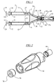
- FIG. 1 illustrates a dispenser, generally indicated at 2 and having a tip structure 4, for mixing at least two separate streams of components into a combined fluid stream, such as a sealant, or tissue sealant or other combined fluid stream.
- a dispenser generally indicated at 2 and having a tip structure 4, for mixing at least two separate streams of components into a combined fluid stream, such as a sealant, or tissue sealant or other combined fluid stream.
- dispenser 2 includes at least two fluid component sources, illustrated in the form of hollow cylinders or barrels 6 and 8, although other source containers from which fluid components are provided may be used.
- each barrel 6, 8 has a generally cylindrical interior or bore in which one of the fluid components such as fibrinogen or thrombin for forming fibrin tissue sealant is stored.
- the distal end 7, 9, respectively, of each barrel has an outlet port 11, 13, respectively, for communicating with the dispensing tip structure, generally at 4.
- each barrel 6, 8 preferably slidably receives a piston or plunger 10, 12, respectively, for ejecting the sealant component from the respective bore.
- a plunger or pusher 14, 16 is associated with each piston and extends proximally from each respective bore.
- a thumb-rest 18, 20 is preferably associated with each plunger 14, 16 and may be actuated or pushed manually or automatically to eject the component. The thumb-rests 18, 20 may be actuated either independently or simultaneously, such as by a common actuator or yoke that couples the plungers together for simultaneous movement.
- the illustrated tip assembly or structure is a multi-part assembly and includes a flow director or Y-piece 26.
- the Y-piece 26 has a proximal end 22 and a distal end 24 and comprises walls that define respective first and second passageways 28 and 30.
- Each passageway 28, 30 communicates with a respective bore of the barrels 6, 8 to allow the respective component to exit the distal end 24 in a downstream direction.
- the inlet to each passageway 28 and 30 is suitable for attachment to one of the outlets from barrels to 6, 8 such as, for example, by a luer fitting or other attachments as will be apparent to persons of skill in the relevant field.
- manually actuated plungers are illustrated for dispensing the fluid components, other types of devices may be used in connection with the present invention including manually or electrically actuated dispensers. Further, as noted above, it is contemplated that the present invention is not limited to dispensers for sealant and may be used to combine two or more components for other combined fluid streams for other applications within or outside of the medical field.
- each of the first and second passageways 28, 30 communicates with one of the components as a separate fluid stream and directs the separate fluid streams out of exit openings 32, 34 located in an end face 36 of the Y-piece 26.
- the exit openings 32, 34 of each passageway 28, 30 have a predefined cross-sectional area through which each component flows.
- the cross-sectional areas preferably are sized to correspond to a ratio of the amount of the two components that are to be mixed. In the illustrated embodiment, the cross-sectional areas are identical, so the components will be mixed in a 1:1 ratio, however, other ratios may be selected.
- the Y-piece 26 is a conduit in which the passageways 28, 30 are located, and near the end face 36, the Y-piece has a generally cylindrical shaped outer surface 38 which may be slightly tapered to provide a luer tip fitting.
- the first and second passageways 28, 30 extend linearly along their length for ease of manufacturing.
- the passageways 28, 30 extend at an angle relative to one another such that the directions of the fluid flow out of the exit openings 32, 34 at the end face 36 are not parallel to one another or parallel to the axis of the Y-piece as the fluid component streams are directed into a mixing space 40.
- the mixing space 40 comprises a cylindrical open space, although other shapes may be provided as well.
- the mixing space 40 may be located in an interior passage 41 of a separate spray head body 42, as shown in FIGs. 1, 2 and 3 .
- the separate spray head body 42 acts as a conduit and includes an inlet end 43 which can removably attach to the cylindrical outer surface 38 of the Y-piece 26, such as, for example, by a luer fitting or other attachments as will be apparent to persons of skill in the relevant field.
- the spray head body 42 includes an exterior surface shaped to provide manual gripping surface areas to facilitate twisting of the spray head body onto the Y-piece 26.
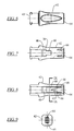
- a separator element 44 which, in the illustrated embodiment shown in detail in FIGs. 4 and 5 , is a hollow cylindrical member having four longitudinally extending interior walls 46a, 46b, 46c, 46d that are arranged at an angular spacing of 90 degrees from adjacent walls. These four walls 46a, 46b, 46c, 46d extend only a portion of the longitudinal length of the separator element in the embodiment shown in FIG. 4 . In this arrangement, the four walls 46a, 46b, 46c, 46d meet at a radial center 47 of the separator element 44. The four walls 46a, 46b, 46c, 46d divide the interior of the separator element 44 into four separate longitudinal channels 48a, 48b, 48c, 48d.
- the longitudinal channels 48a, 48b, 48c, 48d redirect the angled fluid flow coming from the passageways 28, 30 into an axial direction, and also allow for some lateral expansion of the fluid flow streams.
- the interior walls 46a, 46b, 46c, 46d each have a thickness that is less than one half of the diameter of the passageway exit openings 32, 34 (shown also in FIG. 11 ).
- the separator element 44 is press fit within the interior passage 41 of the spray head body42 and in a further embodiment the element 44 is formed of an elastomeric material such that it can be compressed slightly as it is being press-fitted in place, and its resiliency will assist in holding it in place within the spray head body 42.
- the separator element 44 When the spray head body 42 is attached to the Y-piece 26, the separator element 44 is located in abutting relationship to the end face 36 of the Y-piece 26 as shown in FIGs. 1 and 10 , such that the exit openings 32, 34 of the passageways 28, 30 will lead directly into the separate channels 48a, 48b, 48c, 48d.
- a tight engagement between the separator element 44 and the end face 36 may be achieved by using the end face to contactingly press against the separator element 44.
- the interior passage 41 of the spray head body 42 may be provided with a detent 49, such as a raised annular ring, and an exterior surface of the separator element 44 may also be provided with a detent 50.
- the separator element 44 is inserted into the interior passage 41 of the spray head body 42, from the inlet end 43, the detent 50 of the separator element will pass the detent 49 of the interior passage, and the flexible and resilient material of the separator element will allow such passage, and will thereafter restore the shape of the separator element such that the separator element will be retained in the spray head body 42 as part of a spray head assembly.
- the end face 36 of the Y-piece will engage the separator element 44, as shown in FIG. 10 , and will move the separator element even further into the interior passage 41 of the spray head body 42. If detents are provided, the engagement of the detent 49 with the separator element 44 and the engagement of the detent 50 with the interior passage 41, along with the resiliency of the separator element will assure that the separator element will remain sealingly engaged with the end face 36 of the Y-piece 26.
- An accommodation is provided for Y-pieces 26 having some small variation in the luer tip 38, such as for Y-pieces made by different manufacturers or made in different manufacturing runs, by making the separator element 44 from an elastic and flexible material. That is, the outer surface 28 of the Y-piece 26 and the inlet end 43 of the interior passage 41 are provided with complementary tapers to allow for a snug luer connection between the components. This connection is easily obtained by a twisting movement of the spray head body 42 onto the Y-piece 26. Slight variations in the tapers and/or lengths of the Y-piece 26 at the outer surface (luer tip) 28 up to the end face 36, may result in engagement by the end face with the separator element 44 either earlier or later from one set of components to the next.
- the walls of the separator element will be able to flex or buckle to effectively shorten the length of the separator element. So, if the end face 36 presses a distal end of the separator element 44 or the mixing element (as described below) against a shoulder (also discussed below) in the interior passage 41 before the luer tip 28 is sealingly engaged with the interior passage of the spray head body 42, the luer tip will be able to continue to move inwardly until the snug connection is made between the Y piece 26 and the spray head body 42.
- the separator element 44 is only loosely (in a longitudinal sense) held in the interior passage 41, the separator element will be able to move longitudinally in the interior passage for some distance before the separator element will be pressed against a fixed stop, such as a shoulder. Therefore, this loose positioning of the separator element 44 within the interior passage 41 will also accommodate some variation of the luer tip.
- the separator element 44 is provided with four separate channels 48a, 48b, 48c, 48d, each angularly centered 90 degrees from its neighbors, then the two flow streams from the two passageways 28, 30 will remain separated from each other as the flow streams are re-oriented into an axial direction flow in the separate channels.
- the angular orientation of the separator element 44 within the mixing space 40 is not critical, and the separator element will work effectively in any angular orientation.
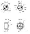
- one of the passageway exit openings 32 aligns nearly completely with one of the separate channels 48a, while the other passageway exit opening 34 aligns with an opposite channel 48c.
- a cross-sectional area of each separate channel 48a, 48b, 48c, 48d is larger than a cross-sectional area of its associated passageway exit opening 32, 34.
- FIG. 12 there is shown another random angular orientation of the separator element 44 in the mixing space 40.
- one of the walls 46a intersects the first passageway exit opening 32, such that the first passageway communicates with two adjacent channels 48d and 48a.
- An opposite wall 46c intersects the second passageway exit opening 34, such that the second passageway communicates with the other two separate channels 48c and 48d.
- the thickness of the walls 46a, 46b, 46c, 46d is less than one half of the diameter of the passageway exit openings 32, 34, so as to not severely impede the flow of fluid from the passageways 28, 30 in the event that the walls are positioned directly over a passageway exit opening.
- each separate channel 48a, 48b, 48c, 48d communicates with only one passageway 28, 30 so the fluids from the two passageways remain isolated from each other while in the separate channels.
- the direction of the fluid flow of the fluids from the passageways 28, 30 are redirected into an axial direction by the walls 46a, 46b, 46c, 46d of the separate channels 48a, 48b, 48c, 48d.
- While the embodiment illustrated shows two passageways 28, 30 and four separate channels 48a, 48b, 48c, 48d, other numbers of passageways and channels could be utilized, so long as the exit openings 32, 34 of the passageways are angularly spaced apart at equal angles from each other (at an angle of 360 degrees divided by the number of passageway exit openings) and so long as the separator element 44 is provided with a number of interior longitudinal walls 46a, 46b, 46c, 46d that is twice the number of passageways, and with the longitudinal walls being angularly spaced from each other at half of the angle of the spacing of the exit openings.
- each exit opening will communicate with only one or two adjacent separate channels and the fluid from each passageway will be kept isolated from all other fluids while still in the separator element.
- a separate channel 48a, 48b, 48c, 48d is located at a downstream end of each passageway 28, 30.
- each passageway exit opening will communicate with at least one and no more than two channels and no channel will communicate with more than one passageway exit opening.
- the separator element 44 may include an axially extending perimeter wall portion 51 having no interior axially extending walls.
- This extending perimeter wall portion 51 defines a portion of a mixing chamber 52 communicating at an upstream end with all of the separate channels 48a, 48b, 48c, 48d and in which the fluids from the passageways 28, 30 are free to mix together.
- the cross-sectional area in the mixing chamber 52 is larger than the cross-sectional area of each of the separate channels 48a, 48b, 48c, 48d.
- the cross-sectional area of the portion of the mixing chamber 52 within the extending perimeter wall portion 51 is larger than the combined cross-sectional area of all of the separate channels 48a, 48b, 48c, 48d.
- the axially extending perimeter wall portion 51 may include a fixture 53, in the form of a recessed space or slightly larger internal diameter, for receiving a mixing element 54 in a press-fit engagement.
- a mixing element 54 may be used, to assist in the thorough mixing of the fluid streams, one effective type of mixing element is described in published US Patent Application 2009/0038701 .
- the mixing element described in that application comprises a three-dimensional lattice defining a plurality of tortuous, interconnecting passages therethrough, the mixer having physical characteristics to sufficiently mix the component streams of the combined fluid stream, the characteristics including a mean flow pore size, thickness and porosity.
- a subassembly of the mixing element 54 and the separator element 44 can be assembled prior to the separator element being introduced into the spray head body 42, as shown in FIG. 4 .
- the press fit engagement between the mixing element 54 and the separator element 44, as well as the resiliency of the separator element will retain the mixing element in place.
- the mixing element 54 may be located in the mixing space 40 without being held in the separator element 44.
- the mixing element 54 will be inserted into the interior passage 41 of the spray head body 42 followed by the insertion of the separator element 44.
- the spray head body 42 may be provided with an internal wall or shoulder 56 against which the mixing element 54, if used, may be engaged to prevent an over-insertion of the mixing element.
- a spring 58 may be provided between the mixing element 54 and the separator element 44.
- the separator element 44 is shown being inserted into the mixing space 40.
- the separator element 44 is pressed against the spring 58 by the end face 36 of the Y-piece 26.
- the spring 58 engages against the mixing element 54 which is pressed against the shoulder 56 in the mixing space 40.
- an unobstructed space 60 for further mixing of the combined fluid stream.
- an integrally formed wedge shaped element 62 which serves to divide the combined fluid stream into two flows which are directed towards an outlet end 64 of the spray head body 42.
- the wedge shaped element 62 is provided downstream of the mixing space 40 to reduce the cross sectional flow area for the combined fluid which results in increasing the stream velocity. Also, the wedge shaped element 62 is shaped to prevent any sharp edges, pockets or corners in the combined stream flow path which would result in dead zones of low flow rate or stagnant fluid thereby allowing clogging formations of fibrin to form.
- the wedge shaped element 62 defines two separate passages 66 for the combined flow stream which lead to an annular space 68 near the outlet end 64 of the spray head body 42.
- a spray nozzle 70 Positioned at the outlet end 64 of the spray head body 42 may be a spray nozzle 70, such as a swirl nozzle, as is known, or other mass breakup unit, to cause the departing fluid to be dispersed in the form of a spray of small droplets.
- the spray nozzle 70 if used, provides for still further mixing of the fluid being dispensed.
- the spray nozzle 70 may be press fit into the outlet end 64 of the spray head body 42 (see FIG. 3 ) by means of an annular body 72 (see FIGs. 16 and 17 ) which is received in the annular space 68 of the spray head body 42.
- a plurality of flow channels 74 lead to a small outlet orifice 76 where the spray of the combined fluid stream is dispensed.
- the flow channels 74 may extend tangentially towards the orifice 76 to give the departing spray a spin.
- the process of assembling the spray head body assembly in one embodiment includes the step of first preparing a subassembly of the separator element 44 and the mixing element 54 by press fitting the mixing element into the fixture 53 of the separator element. This subassembly can then be introduced into the inlet end 43 of the interior passage 41 of the spray head body 42. If the spray head body 42 and/or the separator element 44 include a detent 49, 50, the subassembly is introduced until the detent is engaged so that the subassembly will be held in place in the spray head body. In embodiments where no detent is provided, the subassembly can be introduced into the interior passage 41 for some distance and the separator element 44 will be held in position merely through the engagement of the elastic outer wall of the separator element with the wall of the interior passage.
- the mixing element 54 may be inserted, by itself into the interior passage 41, followed by the insertion of the separator element 44.
- the presence of the separator element 44 will prevent the mixing element 54 from dislodging from the interior passage 41.
- the separator element 44 may be held in place in any of the manners described above.
- the spray nozzle 70 can also be press fit into the outlet end 64 of the spray head body 42 and will be held in place strictly through a frictional engagement.
- the four components of the separator element 44, the mixing element 54, the spray nozzle 70 and the spray head body 42 comprise the spray head body assembly which may be assembled in accordance with the steps described above.
- the spray head body assembly can be used in conjunction with the dispenser 2 by the steps of inserting the luer tip 28 of the Y piece 26 into the inlet end 43 of the interior passage 41 of the spray head body 42 (as a part of the spray head body assembly) and twisting the spray head body relative to the Y piece as the insertion occurs.
- the luer connection between the components will effect a snug and sealed connection between the Y piece 26 and the spray head body 42, and will engage the end face 36 of the Y piece with the separator element 44 so that the passageway exit openings will communicate with only one or two channels, and so that each channel will communicate with no more than one passageway exit opening as described above.
- the combined fluid stream will be split into separate streams by the wedge shaped element 62 where the streams will flow through a smaller cross section passage 66 with greater velocity via a smooth transition, and into the annular space 68 in the spray head body 42. From the annular space 68, the combined stream will flow via one of the channels 74 in the spray nozzle 70 to the exit orifice 76 where the combined stream will be broken into small droplets as it is dispensed.
- the spray stream will be continuously ejected from the spray nozzle 70, which will prevent clogging of the combined stream in the spray head body 42, such as due to the formation of fibrin. Even brief stoppages of the movement of the plungers 10 12 will generally not cause a clogging of the spray head body 42. However, in some procedures it is necessary to stop the dispensing for some period of time before resuming the dispensing, such as for more than 10 or 20 seconds. In those situations, it may be that the spray head body 42 will become clogged to the extent that fluid can no longer be dispensed from the spray nozzle 70 to a sufficient degree, if at all.
- the spray head body assembly can be easily and quickly removed and replaced by medical personnel simply by twisting the spray head body 42 relative to the Y piece 26 while pulling the spray head body away from the Y piece to disengage the luer connection.
- a fresh spray head body assembly can then be assembled onto the Y piece 26 in the manner described above by inserting the luer connection 28 of the Y piece 26 into the inlet 43 of the interior passage 41 of the spray head body 42 and twisting the spray head body relative to the Y piece.
- the medical personnel can continue to dispense the fluids from the dispenser 2 with a resumption of moving the plungers 10, 12 as described above.
Landscapes
- Health & Medical Sciences (AREA)
- Chemical Kinetics & Catalysis (AREA)
- Chemical & Material Sciences (AREA)
- Surgery (AREA)
- Life Sciences & Earth Sciences (AREA)
- Molecular Biology (AREA)
- Heart & Thoracic Surgery (AREA)
- Medical Informatics (AREA)
- Biomedical Technology (AREA)
- Animal Behavior & Ethology (AREA)
- General Health & Medical Sciences (AREA)
- Public Health (AREA)
- Veterinary Medicine (AREA)
- Engineering & Computer Science (AREA)
- Nuclear Medicine, Radiotherapy & Molecular Imaging (AREA)
- Nozzles (AREA)
Claims (8)
- Vorrichtung (2) zum Mischen von wenigstens zwei separaten Komponentenströmen, die, wenn vermischt, einen kombinierten Fluidstrom ausbilden, wobei die Vorrichtung Folgendes umfasst:eine Leitung (26) mit wenigstens zwei separaten Durchlässen (28, 30), wobei jeder Durchlass mit einem separaten Komponentenstrom kommuniziert und angeordnet ist, den separaten Komponentenstrom in einer Richtung stromabwärts zu Auslassöffnungen (32, 34) der Durchlässe in einer Stirnfläche (36) der Leitung zu leiten, wobei die Austrittsöffnungen jeweils eine vorgegebene Querschnittsströmungsfläche aufweisen und in gleichmäßigen Winkelausrichtungen winklig voneinander beabstandet sind;ein Trennerelement (44) im Eingriff mit der Stirnfläche der Leitung, wobei das Trennerelement zwei separate Kanäle (48a, 48b, 48c, 48d) für jeden Durchlass (28, 30) umfasst und interne Längstrennwände (46a, 46b, 46c, 46d) zwischen jedem der separaten Kanäle bereitgestellt sind, wobei die internen Längstrennwände aufeinander bezogen in Winkelpositionen angeordnet sind, deren Winkel der Hälfte der Winkel der Winkelpositionen der Durchlass-Austrittsöffnungen (32, 34) entsprechen;eine Mischkammer (40, 52), die mit allen separaten Kanälen kommuniziert, wobei die Mischkammer angeordnet ist, jeden der Komponentenströme an einem stromaufwärts angeordneten Ende davon aufzunehmen, und ein Mischen der Komponentenströme zu ermöglichen; undeinen Auslass (64, 70), stromabwärts von der Mischkammer angeordnet, durch den der kombinierte Fluidstrom ausgegeben wird.
- Vorrichtung nach Anspruch 1, einschließlich eines Mischelements (54), an einem stromabwärts angeordneten Ende der Mischkammer (40, 52) angeordnet, wobei das Mischelement konfiguriert ist, die Komponentenströme gründlich in den kombinierten Fluidstrom zu vermischen.
- Vorrichtung nach Anspruch 2, wobei das Mischelement (54) ein dreidimensionales Gitter umfasst, das mehrere verschlungene, miteinander verbundene Durchgänge dahindurch definiert.
- Vorrichtung nach einem der Ansprüche 1 bis 3, einschließlich einer am Auslass (64) angeordneten Sprühdüse (70), um den kombinierten Fluidstrom auszugeben.
- Vorrichtung nach Anspruch 4, wobei die Sprühdüse (70) eine Dralldüse umfasst.
- Vorrichtung nach einem der vorhergehenden Ansprüche, wobei die Mischkammer (40, 52) eine Querschnittsströmungsfläche aufweist, die größer ist als eine kombinierte Gesamtquerschnittsströmungsfläche aller separaten Kanäle (48a, 48b, 48c, 48d).
- Vorrichtung nach einem der vorhergehenden Ansprüche, wobei das Trennerelement (44) und die Mischkammer (40, 52) in einem von der Leitung (26) separaten entfernbaren Sprühkopf (42), in dem die wenigstens zwei separaten Durchlässe (28, 30) aufgenommen sind, bereitgestellt sind, wobei der entfernbare Sprühkopf über einen Luer-Anschluss (38) mit der Leitung verbindbar ist.
- Vorrichtung (2) zum Mischen von zwei separaten Komponentenströmen, die, wenn vermischt, einen kombinierten Fluidstrom ausbilden, wobei die Vorrichtung Folgendes umfasst:eine Leitung (26) mit einer zylindrischen Außenoberfläche mit zwei separaten internen Durchlässen (28, 30), wobei jeder Durchlass mit einem separaten Komponentenstrom kommuniziert und angeordnet ist, den separaten Komponentenstrom in einer Längsrichtung stromabwärts zu leiten, wobei die Durchlässe an einem Abschlussende (36) der Leitung durch Austrittsöffnungen (32, 34) aus der Leitung austreten, wobei die Austrittsöffnungen jeweils eine vorgegebene Querschnittsströmungsfläche aufweisen, die mit der anderen identisch ist, und die jeweils voneinander um 180° winklig beabstandet sind;einen Sprühkopfkörper (42) mit einem internen Durchgang (41), der sich längs um eine Gesamtlänge des Sprühkopfkörpers erstreckt und ein Einlassende (43) und ein Auslassende (64) definiert, wobei der Sprühkopfkörper an seinem Einlassende über einen Luer-Anschluss (38) mit der Durchlassleitung verbindbar ist;ein Trennerelement (44), angeordnet innerhalb des internen Durchgangs des Sprühkopfkörpers, wobei das Trennerelement vier interne Längswände (46a, 46b, 46c, 46d) aufweist, die um 90° winklig voneinander beabstandet sind, um vier separate Kanäle (48a, 48b, 48c, 48d) voneinander zu trennen, wobei eine Dicke der Längswände geringer ist als eine Hälfte eines Durchmessers der Durchlassaustrittsöffnungen und die separaten Kanäle jeweils eine größere Querschnittsströmungsfläche aufweisen als die Durchlassaustrittsöffnungen,eine Mischkammer (40, 52), angeordnet zwischen dem Trennerelement und dem Auslassende des Sprühkopfkörpers, die mit allen separaten Kanälen des Trennerelements kommuniziert,ein Mischelement (54), um wenigstens einen Abschnitt der Mischkammer von den Kanälen des Trennerelements beabstandet und konfiguriert, die Komponentenströme gründlich in den kombinierten Fluidstrom zusammenzumischen, undeine Sprühdüse (70), stromabwärts von dem Mischelement angeordnet, um den kombinierten Fluidstrom auszugeben.
Applications Claiming Priority (2)
| Application Number | Priority Date | Filing Date | Title |
|---|---|---|---|
| US13/662,050 US9381005B2 (en) | 2012-10-26 | 2012-10-26 | Spray head for two component mixer |
| PCT/US2013/066579 WO2014066616A1 (en) | 2012-10-26 | 2013-10-24 | Spray head for two component mixer |
Publications (2)
| Publication Number | Publication Date |
|---|---|
| EP2911775A1 EP2911775A1 (de) | 2015-09-02 |
| EP2911775B1 true EP2911775B1 (de) | 2016-10-05 |
Family
ID=49551791
Family Applications (1)
| Application Number | Title | Priority Date | Filing Date |
|---|---|---|---|
| EP13786834.5A Active EP2911775B1 (de) | 2012-10-26 | 2013-10-24 | Sprühkopf für einen zweikomponentenmischer |
Country Status (7)
| Country | Link |
|---|---|
| US (1) | US9381005B2 (de) |
| EP (1) | EP2911775B1 (de) |
| AU (1) | AU2013334514A1 (de) |
| BR (1) | BR112015009408A2 (de) |
| CA (1) | CA2889294A1 (de) |
| MX (1) | MX2015005315A (de) |
| WO (1) | WO2014066616A1 (de) |
Families Citing this family (15)
| Publication number | Priority date | Publication date | Assignee | Title |
|---|---|---|---|---|
| WO2014160083A1 (en) | 2013-03-13 | 2014-10-02 | Applied Cardiovascular Solutions, Llc. | Methods, compositions, and devices for the occlusion of cavities and passageways |
| US10952709B2 (en) | 2014-04-04 | 2021-03-23 | Hyperbranch Medical Technology, Inc. | Extended tip spray applicator for two-component surgical sealant, and methods of use thereof |
| US9572555B1 (en) * | 2015-09-24 | 2017-02-21 | Ethicon, Inc. | Spray or drip tips having multiple outlet channels |
| CN105617899B (zh) * | 2016-03-16 | 2017-09-19 | 熊菊莲 | 用于气液混合的装置 |
| CN105617924B (zh) * | 2016-03-16 | 2017-09-19 | 熊菊莲 | 安全可靠的混合装置 |
| CN105749775B (zh) * | 2016-03-16 | 2017-09-19 | 熊菊莲 | 一种气液混合装置 |
| CN105617897B (zh) * | 2016-03-25 | 2017-09-19 | 熊菊莲 | 一种混合器 |
| CN105688703B (zh) * | 2016-03-25 | 2017-09-19 | 熊菊莲 | 一种安全可靠的混合器 |
| CN105664775B (zh) * | 2016-03-25 | 2017-09-19 | 熊菊莲 | 一种可远程操控的混合设备 |
| JP2017177073A (ja) * | 2016-03-31 | 2017-10-05 | テルモ株式会社 | 塗布具 |
| CN107160579B (zh) * | 2017-06-22 | 2019-06-28 | 江阴市双叶机械有限公司 | 一种高粘度多组分密封胶混合充填一体化工装以及方法 |
| CN107715719B (zh) * | 2017-09-11 | 2021-01-29 | 天津科技大学 | 一种可实现射流泵系统尾管二次射流加料的喷嘴 |
| US11911787B1 (en) | 2019-08-16 | 2024-02-27 | Gary Hammerlund | Split manifold and method for multiple part fluid applications |
| CN112654418A (zh) * | 2020-03-27 | 2021-04-13 | 深圳市大疆创新科技有限公司 | 混合装置、混合控制方法及可移动平台 |
| CN113231214B (zh) * | 2021-04-23 | 2022-03-04 | 哈尔滨瀚邦医疗科技有限公司 | 腔镜配合管 |
Family Cites Families (18)
| Publication number | Priority date | Publication date | Assignee | Title |
|---|---|---|---|---|
| US4316673A (en) * | 1978-08-08 | 1982-02-23 | General Dynamics, Pomona Division | Mixing device for simultaneously dispensing two-part liquid compounds from packaging kit |
| US4505157A (en) * | 1983-08-05 | 1985-03-19 | Transamerica Delaval Inc. | Transducers with quick dome connect systems |
| AT379311B (de) | 1984-03-29 | 1985-12-27 | Immuno Ag | Vorrichtung zur applikation eines gewebeklebstoffes |
| DE3725552A1 (de) | 1987-08-01 | 1989-02-09 | Hoechst Ag | Spruehkopf zum applizieren eines mehrkomponentenmaterials mittels gas |
| US5116315A (en) | 1989-10-03 | 1992-05-26 | Hemaedics, Inc. | Biological syringe system |
| JP2555549B2 (ja) | 1992-09-26 | 1996-11-20 | 財団法人化学及血清療法研究所 | 生体組識接着剤塗布器具 |
| AT400304B (de) | 1994-02-28 | 1995-12-27 | Immuno Ag | Vorrichtung zur applikation eines mehrkomponenten-gewebeklebstoffes |
| ATE206078T1 (de) * | 1994-06-28 | 2001-10-15 | Aventis Behring Gmbh | Vorrichtung zum versprühen eines gemischs aus zwei komponenten |
| ATE244584T1 (de) | 1995-01-16 | 2003-07-15 | Baxter Int | Selbsttragende flächengebilde aus vernetztem fibrin zur hemmung von postoperativen adhäsionen |
| EP0957772A2 (de) | 1995-06-06 | 1999-11-24 | Quantic Biomedical Partners | Vorrichtung zum vorbereiten und auftragen einer wundabdeckung sowie entsprechendes verfahren |
| US6461361B1 (en) | 1998-05-01 | 2002-10-08 | Baxter International Inc. | Gas-driven spraying of mixed sealant agents |
| ATA49899A (de) | 1999-03-19 | 2002-06-15 | Immuno Ag | Verfahren und vorrichtung zum mischen von komponenten |
| US6802822B1 (en) | 2000-03-31 | 2004-10-12 | 3M Innovative Properties Company | Dispenser for an adhesive tissue sealant having a flexible link |
| US6585696B2 (en) | 2000-12-22 | 2003-07-01 | Baxter International, Inc. | Method and apparatus for applying a medically useful multiple component material |
| US7037289B2 (en) | 2001-09-12 | 2006-05-02 | 3M Innovative Properties Company | Apparatus and methods for dispensing an adhesive tissue sealant |
| EP2213245B1 (de) | 2006-01-17 | 2012-07-04 | Baxter International Inc. | Mischvorrichtung und -verfahren |
| US20090038701A1 (en) | 2006-01-17 | 2009-02-12 | Baxter International Inc. | Device, system and method for mixing |
| US20100114158A1 (en) | 2008-09-29 | 2010-05-06 | Nerites Corporation | Delivery assembly, delivery tip, and method of using same |
-
2012
- 2012-10-26 US US13/662,050 patent/US9381005B2/en active Active
-
2013
- 2013-10-24 MX MX2015005315A patent/MX2015005315A/es unknown
- 2013-10-24 CA CA2889294A patent/CA2889294A1/en not_active Abandoned
- 2013-10-24 EP EP13786834.5A patent/EP2911775B1/de active Active
- 2013-10-24 BR BR112015009408A patent/BR112015009408A2/pt not_active IP Right Cessation
- 2013-10-24 AU AU2013334514A patent/AU2013334514A1/en not_active Abandoned
- 2013-10-24 WO PCT/US2013/066579 patent/WO2014066616A1/en active Application Filing
Also Published As
| Publication number | Publication date |
|---|---|
| US20140117116A1 (en) | 2014-05-01 |
| WO2014066616A1 (en) | 2014-05-01 |
| US9381005B2 (en) | 2016-07-05 |
| MX2015005315A (es) | 2015-10-30 |
| EP2911775A1 (de) | 2015-09-02 |
| BR112015009408A2 (pt) | 2017-07-04 |
| AU2013334514A1 (en) | 2015-05-14 |
| CA2889294A1 (en) | 2014-05-01 |
Similar Documents
| Publication | Publication Date | Title |
|---|---|---|
| EP2911775B1 (de) | Sprühkopf für einen zweikomponentenmischer | |
| US8672237B2 (en) | Device for mixing and dispensing of two-component reactive surgical sealant | |
| EP2111918B1 (de) | Silikonsprühspitze | |
| US9125633B2 (en) | Device for mixing and dispensing of two-component reactive surgical sealant | |
| EP2895259B1 (de) | Luftlose, nichtverstopfende spitzenanordnung und vorrichtung damit | |
| US11872584B2 (en) | Spray devices including side-by-side spray tips having fluid pathways with swirl chambers for dispensing two fluids that chemically react together | |
| EP3015076A1 (de) | Applikator | |
| EP1059957B1 (de) | Turbulenz-mischkopf für gewebeklebstoff-applikator und sprühkopf für selbigen | |
| JP5658544B2 (ja) | 薬液塗布器具キット | |
| US6884230B1 (en) | Dispensing head for a tissue sealant applicator and process of use | |
| KR20170053655A (ko) | 유체의 전달을 위한 최소 폐색 장치 및 사용 방법 | |
| EP3352679B1 (de) | Sprüh- oder tropfspitzen mit mehreren ausgangskanälen | |
| KR102385837B1 (ko) | 믹스 스프레이 약액 주입기 | |
| US20210100543A1 (en) | Dispensing systems and devices having anti-clogging spray tips for dispensing two or more fluids that react together |
Legal Events
| Date | Code | Title | Description |
|---|---|---|---|
| PUAI | Public reference made under article 153(3) epc to a published international application that has entered the european phase |
Free format text: ORIGINAL CODE: 0009012 |
|
| 17P | Request for examination filed |
Effective date: 20150522 |
|
| AK | Designated contracting states |
Kind code of ref document: A1 Designated state(s): AL AT BE BG CH CY CZ DE DK EE ES FI FR GB GR HR HU IE IS IT LI LT LU LV MC MK MT NL NO PL PT RO RS SE SI SK SM TR |
|
| AX | Request for extension of the european patent |
Extension state: BA ME |
|
| DAX | Request for extension of the european patent (deleted) | ||
| GRAP | Despatch of communication of intention to grant a patent |
Free format text: ORIGINAL CODE: EPIDOSNIGR1 |
|
| INTG | Intention to grant announced |
Effective date: 20160603 |
|
| GRAS | Grant fee paid |
Free format text: ORIGINAL CODE: EPIDOSNIGR3 |
|
| GRAA | (expected) grant |
Free format text: ORIGINAL CODE: 0009210 |
|
| AK | Designated contracting states |
Kind code of ref document: B1 Designated state(s): AL AT BE BG CH CY CZ DE DK EE ES FI FR GB GR HR HU IE IS IT LI LT LU LV MC MK MT NL NO PL PT RO RS SE SI SK SM TR |
|
| REG | Reference to a national code |
Ref country code: GB Ref legal event code: FG4D |
|
| REG | Reference to a national code |
Ref country code: CH Ref legal event code: EP |
|
| REG | Reference to a national code |
Ref country code: AT Ref legal event code: REF Ref document number: 834145 Country of ref document: AT Kind code of ref document: T Effective date: 20161015 |
|
| REG | Reference to a national code |
Ref country code: FR Ref legal event code: PLFP Year of fee payment: 4 |
|
| REG | Reference to a national code |
Ref country code: IE Ref legal event code: FG4D |
|
| REG | Reference to a national code |
Ref country code: DE Ref legal event code: R096 Ref document number: 602013012528 Country of ref document: DE |
|
| REG | Reference to a national code |
Ref country code: NL Ref legal event code: MP Effective date: 20161005 |
|
| REG | Reference to a national code |
Ref country code: LT Ref legal event code: MG4D |
|
| PG25 | Lapsed in a contracting state [announced via postgrant information from national office to epo] |
Ref country code: BE Free format text: LAPSE BECAUSE OF NON-PAYMENT OF DUE FEES Effective date: 20161031 Ref country code: LV Free format text: LAPSE BECAUSE OF FAILURE TO SUBMIT A TRANSLATION OF THE DESCRIPTION OR TO PAY THE FEE WITHIN THE PRESCRIBED TIME-LIMIT Effective date: 20161005 |
|
| REG | Reference to a national code |
Ref country code: AT Ref legal event code: MK05 Ref document number: 834145 Country of ref document: AT Kind code of ref document: T Effective date: 20161005 |
|
| PG25 | Lapsed in a contracting state [announced via postgrant information from national office to epo] |
Ref country code: SE Free format text: LAPSE BECAUSE OF FAILURE TO SUBMIT A TRANSLATION OF THE DESCRIPTION OR TO PAY THE FEE WITHIN THE PRESCRIBED TIME-LIMIT Effective date: 20161005 Ref country code: NO Free format text: LAPSE BECAUSE OF FAILURE TO SUBMIT A TRANSLATION OF THE DESCRIPTION OR TO PAY THE FEE WITHIN THE PRESCRIBED TIME-LIMIT Effective date: 20170105 Ref country code: LT Free format text: LAPSE BECAUSE OF FAILURE TO SUBMIT A TRANSLATION OF THE DESCRIPTION OR TO PAY THE FEE WITHIN THE PRESCRIBED TIME-LIMIT Effective date: 20161005 Ref country code: GR Free format text: LAPSE BECAUSE OF FAILURE TO SUBMIT A TRANSLATION OF THE DESCRIPTION OR TO PAY THE FEE WITHIN THE PRESCRIBED TIME-LIMIT Effective date: 20170106 |
|
| PG25 | Lapsed in a contracting state [announced via postgrant information from national office to epo] |
Ref country code: ES Free format text: LAPSE BECAUSE OF FAILURE TO SUBMIT A TRANSLATION OF THE DESCRIPTION OR TO PAY THE FEE WITHIN THE PRESCRIBED TIME-LIMIT Effective date: 20161005 Ref country code: BE Free format text: LAPSE BECAUSE OF FAILURE TO SUBMIT A TRANSLATION OF THE DESCRIPTION OR TO PAY THE FEE WITHIN THE PRESCRIBED TIME-LIMIT Effective date: 20161005 Ref country code: PL Free format text: LAPSE BECAUSE OF FAILURE TO SUBMIT A TRANSLATION OF THE DESCRIPTION OR TO PAY THE FEE WITHIN THE PRESCRIBED TIME-LIMIT Effective date: 20161005 Ref country code: HR Free format text: LAPSE BECAUSE OF FAILURE TO SUBMIT A TRANSLATION OF THE DESCRIPTION OR TO PAY THE FEE WITHIN THE PRESCRIBED TIME-LIMIT Effective date: 20161005 Ref country code: IS Free format text: LAPSE BECAUSE OF FAILURE TO SUBMIT A TRANSLATION OF THE DESCRIPTION OR TO PAY THE FEE WITHIN THE PRESCRIBED TIME-LIMIT Effective date: 20170205 Ref country code: AT Free format text: LAPSE BECAUSE OF FAILURE TO SUBMIT A TRANSLATION OF THE DESCRIPTION OR TO PAY THE FEE WITHIN THE PRESCRIBED TIME-LIMIT Effective date: 20161005 Ref country code: PT Free format text: LAPSE BECAUSE OF FAILURE TO SUBMIT A TRANSLATION OF THE DESCRIPTION OR TO PAY THE FEE WITHIN THE PRESCRIBED TIME-LIMIT Effective date: 20170206 Ref country code: RS Free format text: LAPSE BECAUSE OF FAILURE TO SUBMIT A TRANSLATION OF THE DESCRIPTION OR TO PAY THE FEE WITHIN THE PRESCRIBED TIME-LIMIT Effective date: 20161005 Ref country code: NL Free format text: LAPSE BECAUSE OF FAILURE TO SUBMIT A TRANSLATION OF THE DESCRIPTION OR TO PAY THE FEE WITHIN THE PRESCRIBED TIME-LIMIT Effective date: 20161005 Ref country code: FI Free format text: LAPSE BECAUSE OF FAILURE TO SUBMIT A TRANSLATION OF THE DESCRIPTION OR TO PAY THE FEE WITHIN THE PRESCRIBED TIME-LIMIT Effective date: 20161005 |
|
| REG | Reference to a national code |
Ref country code: CH Ref legal event code: PL |
|
| REG | Reference to a national code |
Ref country code: DE Ref legal event code: R097 Ref document number: 602013012528 Country of ref document: DE |
|
| REG | Reference to a national code |
Ref country code: IE Ref legal event code: MM4A |
|
| PG25 | Lapsed in a contracting state [announced via postgrant information from national office to epo] |
Ref country code: SK Free format text: LAPSE BECAUSE OF FAILURE TO SUBMIT A TRANSLATION OF THE DESCRIPTION OR TO PAY THE FEE WITHIN THE PRESCRIBED TIME-LIMIT Effective date: 20161005 Ref country code: CH Free format text: LAPSE BECAUSE OF NON-PAYMENT OF DUE FEES Effective date: 20161031 Ref country code: RO Free format text: LAPSE BECAUSE OF FAILURE TO SUBMIT A TRANSLATION OF THE DESCRIPTION OR TO PAY THE FEE WITHIN THE PRESCRIBED TIME-LIMIT Effective date: 20161005 Ref country code: DK Free format text: LAPSE BECAUSE OF FAILURE TO SUBMIT A TRANSLATION OF THE DESCRIPTION OR TO PAY THE FEE WITHIN THE PRESCRIBED TIME-LIMIT Effective date: 20161005 Ref country code: EE Free format text: LAPSE BECAUSE OF FAILURE TO SUBMIT A TRANSLATION OF THE DESCRIPTION OR TO PAY THE FEE WITHIN THE PRESCRIBED TIME-LIMIT Effective date: 20161005 Ref country code: MC Free format text: LAPSE BECAUSE OF FAILURE TO SUBMIT A TRANSLATION OF THE DESCRIPTION OR TO PAY THE FEE WITHIN THE PRESCRIBED TIME-LIMIT Effective date: 20161005 Ref country code: CZ Free format text: LAPSE BECAUSE OF FAILURE TO SUBMIT A TRANSLATION OF THE DESCRIPTION OR TO PAY THE FEE WITHIN THE PRESCRIBED TIME-LIMIT Effective date: 20161005 Ref country code: LI Free format text: LAPSE BECAUSE OF NON-PAYMENT OF DUE FEES Effective date: 20161031 |
|
| PLBE | No opposition filed within time limit |
Free format text: ORIGINAL CODE: 0009261 |
|
| STAA | Information on the status of an ep patent application or granted ep patent |
Free format text: STATUS: NO OPPOSITION FILED WITHIN TIME LIMIT |
|
| PG25 | Lapsed in a contracting state [announced via postgrant information from national office to epo] |
Ref country code: IT Free format text: LAPSE BECAUSE OF FAILURE TO SUBMIT A TRANSLATION OF THE DESCRIPTION OR TO PAY THE FEE WITHIN THE PRESCRIBED TIME-LIMIT Effective date: 20161005 Ref country code: LU Free format text: LAPSE BECAUSE OF NON-PAYMENT OF DUE FEES Effective date: 20161024 Ref country code: BG Free format text: LAPSE BECAUSE OF FAILURE TO SUBMIT A TRANSLATION OF THE DESCRIPTION OR TO PAY THE FEE WITHIN THE PRESCRIBED TIME-LIMIT Effective date: 20170105 Ref country code: SM Free format text: LAPSE BECAUSE OF FAILURE TO SUBMIT A TRANSLATION OF THE DESCRIPTION OR TO PAY THE FEE WITHIN THE PRESCRIBED TIME-LIMIT Effective date: 20161005 |
|
| 26N | No opposition filed |
Effective date: 20170706 |
|
| REG | Reference to a national code |
Ref country code: FR Ref legal event code: PLFP Year of fee payment: 5 |
|
| PG25 | Lapsed in a contracting state [announced via postgrant information from national office to epo] |
Ref country code: SI Free format text: LAPSE BECAUSE OF FAILURE TO SUBMIT A TRANSLATION OF THE DESCRIPTION OR TO PAY THE FEE WITHIN THE PRESCRIBED TIME-LIMIT Effective date: 20161005 Ref country code: IE Free format text: LAPSE BECAUSE OF NON-PAYMENT OF DUE FEES Effective date: 20161024 |
|
| PG25 | Lapsed in a contracting state [announced via postgrant information from national office to epo] |
Ref country code: HU Free format text: LAPSE BECAUSE OF FAILURE TO SUBMIT A TRANSLATION OF THE DESCRIPTION OR TO PAY THE FEE WITHIN THE PRESCRIBED TIME-LIMIT; INVALID AB INITIO Effective date: 20131024 |
|
| PG25 | Lapsed in a contracting state [announced via postgrant information from national office to epo] |
Ref country code: MT Free format text: LAPSE BECAUSE OF NON-PAYMENT OF DUE FEES Effective date: 20161031 Ref country code: CY Free format text: LAPSE BECAUSE OF FAILURE TO SUBMIT A TRANSLATION OF THE DESCRIPTION OR TO PAY THE FEE WITHIN THE PRESCRIBED TIME-LIMIT Effective date: 20161005 Ref country code: MK Free format text: LAPSE BECAUSE OF FAILURE TO SUBMIT A TRANSLATION OF THE DESCRIPTION OR TO PAY THE FEE WITHIN THE PRESCRIBED TIME-LIMIT Effective date: 20161005 |
|
| REG | Reference to a national code |
Ref country code: FR Ref legal event code: PLFP Year of fee payment: 6 |
|
| PG25 | Lapsed in a contracting state [announced via postgrant information from national office to epo] |
Ref country code: TR Free format text: LAPSE BECAUSE OF FAILURE TO SUBMIT A TRANSLATION OF THE DESCRIPTION OR TO PAY THE FEE WITHIN THE PRESCRIBED TIME-LIMIT Effective date: 20161005 |
|
| PG25 | Lapsed in a contracting state [announced via postgrant information from national office to epo] |
Ref country code: AL Free format text: LAPSE BECAUSE OF FAILURE TO SUBMIT A TRANSLATION OF THE DESCRIPTION OR TO PAY THE FEE WITHIN THE PRESCRIBED TIME-LIMIT Effective date: 20161005 |
|
| REG | Reference to a national code |
Ref country code: DE Ref legal event code: R079 Ref document number: 602013012528 Country of ref document: DE Free format text: PREVIOUS MAIN CLASS: B01F0013000000 Ipc: B01F0033000000 |
|
| PGFP | Annual fee paid to national office [announced via postgrant information from national office to epo] |
Ref country code: GB Payment date: 20230920 Year of fee payment: 11 |
|
| PGFP | Annual fee paid to national office [announced via postgrant information from national office to epo] |
Ref country code: FR Payment date: 20230920 Year of fee payment: 11 |
|
| PGFP | Annual fee paid to national office [announced via postgrant information from national office to epo] |
Ref country code: DE Payment date: 20230920 Year of fee payment: 11 |