EP1998929B1 - Prozesskammer und verfahren für die bearbeitung eines werkstoffs mit einem gerichteten strahl elektromagnetischer strahlung, insbesondere für eine lasersintervorrichtung - Google Patents
Prozesskammer und verfahren für die bearbeitung eines werkstoffs mit einem gerichteten strahl elektromagnetischer strahlung, insbesondere für eine lasersintervorrichtung Download PDFInfo
- Publication number
- EP1998929B1 EP1998929B1 EP07703516A EP07703516A EP1998929B1 EP 1998929 B1 EP1998929 B1 EP 1998929B1 EP 07703516 A EP07703516 A EP 07703516A EP 07703516 A EP07703516 A EP 07703516A EP 1998929 B1 EP1998929 B1 EP 1998929B1
- Authority
- EP
- European Patent Office
- Prior art keywords
- process chamber
- gas
- coupling
- window
- gas flow
- Prior art date
- Legal status (The legal status is an assumption and is not a legal conclusion. Google has not performed a legal analysis and makes no representation as to the accuracy of the status listed.)
- Active
Links
Images
Classifications
-
- B—PERFORMING OPERATIONS; TRANSPORTING
- B23—MACHINE TOOLS; METAL-WORKING NOT OTHERWISE PROVIDED FOR
- B23K—SOLDERING OR UNSOLDERING; WELDING; CLADDING OR PLATING BY SOLDERING OR WELDING; CUTTING BY APPLYING HEAT LOCALLY, e.g. FLAME CUTTING; WORKING BY LASER BEAM
- B23K26/00—Working by laser beam, e.g. welding, cutting or boring
- B23K26/12—Working by laser beam, e.g. welding, cutting or boring in a special atmosphere, e.g. in an enclosure
-
- B—PERFORMING OPERATIONS; TRANSPORTING
- B22—CASTING; POWDER METALLURGY
- B22F—WORKING METALLIC POWDER; MANUFACTURE OF ARTICLES FROM METALLIC POWDER; MAKING METALLIC POWDER; APPARATUS OR DEVICES SPECIALLY ADAPTED FOR METALLIC POWDER
- B22F10/00—Additive manufacturing of workpieces or articles from metallic powder
- B22F10/20—Direct sintering or melting
- B22F10/28—Powder bed fusion, e.g. selective laser melting [SLM] or electron beam melting [EBM]
-
- B—PERFORMING OPERATIONS; TRANSPORTING
- B22—CASTING; POWDER METALLURGY
- B22F—WORKING METALLIC POWDER; MANUFACTURE OF ARTICLES FROM METALLIC POWDER; MAKING METALLIC POWDER; APPARATUS OR DEVICES SPECIALLY ADAPTED FOR METALLIC POWDER
- B22F12/00—Apparatus or devices specially adapted for additive manufacturing; Auxiliary means for additive manufacturing; Combinations of additive manufacturing apparatus or devices with other processing apparatus or devices
- B22F12/40—Radiation means
- B22F12/44—Radiation means characterised by the configuration of the radiation means
-
- B—PERFORMING OPERATIONS; TRANSPORTING
- B22—CASTING; POWDER METALLURGY
- B22F—WORKING METALLIC POWDER; MANUFACTURE OF ARTICLES FROM METALLIC POWDER; MAKING METALLIC POWDER; APPARATUS OR DEVICES SPECIALLY ADAPTED FOR METALLIC POWDER
- B22F12/00—Apparatus or devices specially adapted for additive manufacturing; Auxiliary means for additive manufacturing; Combinations of additive manufacturing apparatus or devices with other processing apparatus or devices
- B22F12/70—Gas flow means
-
- B—PERFORMING OPERATIONS; TRANSPORTING
- B23—MACHINE TOOLS; METAL-WORKING NOT OTHERWISE PROVIDED FOR
- B23K—SOLDERING OR UNSOLDERING; WELDING; CLADDING OR PLATING BY SOLDERING OR WELDING; CUTTING BY APPLYING HEAT LOCALLY, e.g. FLAME CUTTING; WORKING BY LASER BEAM
- B23K26/00—Working by laser beam, e.g. welding, cutting or boring
- B23K26/12—Working by laser beam, e.g. welding, cutting or boring in a special atmosphere, e.g. in an enclosure
- B23K26/123—Working by laser beam, e.g. welding, cutting or boring in a special atmosphere, e.g. in an enclosure in an atmosphere of particular gases
-
- B—PERFORMING OPERATIONS; TRANSPORTING
- B23—MACHINE TOOLS; METAL-WORKING NOT OTHERWISE PROVIDED FOR
- B23K—SOLDERING OR UNSOLDERING; WELDING; CLADDING OR PLATING BY SOLDERING OR WELDING; CUTTING BY APPLYING HEAT LOCALLY, e.g. FLAME CUTTING; WORKING BY LASER BEAM
- B23K26/00—Working by laser beam, e.g. welding, cutting or boring
- B23K26/12—Working by laser beam, e.g. welding, cutting or boring in a special atmosphere, e.g. in an enclosure
- B23K26/127—Working by laser beam, e.g. welding, cutting or boring in a special atmosphere, e.g. in an enclosure in an enclosure
-
- B—PERFORMING OPERATIONS; TRANSPORTING
- B23—MACHINE TOOLS; METAL-WORKING NOT OTHERWISE PROVIDED FOR
- B23K—SOLDERING OR UNSOLDERING; WELDING; CLADDING OR PLATING BY SOLDERING OR WELDING; CUTTING BY APPLYING HEAT LOCALLY, e.g. FLAME CUTTING; WORKING BY LASER BEAM
- B23K26/00—Working by laser beam, e.g. welding, cutting or boring
- B23K26/14—Working by laser beam, e.g. welding, cutting or boring using a fluid stream, e.g. a jet of gas, in conjunction with the laser beam; Nozzles therefor
- B23K26/1462—Nozzles; Features related to nozzles
- B23K26/1464—Supply to, or discharge from, nozzles of media, e.g. gas, powder, wire
-
- B—PERFORMING OPERATIONS; TRANSPORTING
- B29—WORKING OF PLASTICS; WORKING OF SUBSTANCES IN A PLASTIC STATE IN GENERAL
- B29C—SHAPING OR JOINING OF PLASTICS; SHAPING OF MATERIAL IN A PLASTIC STATE, NOT OTHERWISE PROVIDED FOR; AFTER-TREATMENT OF THE SHAPED PRODUCTS, e.g. REPAIRING
- B29C64/00—Additive manufacturing, i.e. manufacturing of three-dimensional [3D] objects by additive deposition, additive agglomeration or additive layering, e.g. by 3D printing, stereolithography or selective laser sintering
- B29C64/10—Processes of additive manufacturing
- B29C64/141—Processes of additive manufacturing using only solid materials
- B29C64/153—Processes of additive manufacturing using only solid materials using layers of powder being selectively joined, e.g. by selective laser sintering or melting
-
- B—PERFORMING OPERATIONS; TRANSPORTING
- B22—CASTING; POWDER METALLURGY
- B22F—WORKING METALLIC POWDER; MANUFACTURE OF ARTICLES FROM METALLIC POWDER; MAKING METALLIC POWDER; APPARATUS OR DEVICES SPECIALLY ADAPTED FOR METALLIC POWDER
- B22F10/00—Additive manufacturing of workpieces or articles from metallic powder
- B22F10/30—Process control
- B22F10/32—Process control of the atmosphere, e.g. composition or pressure in a building chamber
- B22F10/322—Process control of the atmosphere, e.g. composition or pressure in a building chamber of the gas flow, e.g. rate or direction
-
- B—PERFORMING OPERATIONS; TRANSPORTING
- B22—CASTING; POWDER METALLURGY
- B22F—WORKING METALLIC POWDER; MANUFACTURE OF ARTICLES FROM METALLIC POWDER; MAKING METALLIC POWDER; APPARATUS OR DEVICES SPECIALLY ADAPTED FOR METALLIC POWDER
- B22F2998/00—Supplementary information concerning processes or compositions relating to powder metallurgy
-
- Y—GENERAL TAGGING OF NEW TECHNOLOGICAL DEVELOPMENTS; GENERAL TAGGING OF CROSS-SECTIONAL TECHNOLOGIES SPANNING OVER SEVERAL SECTIONS OF THE IPC; TECHNICAL SUBJECTS COVERED BY FORMER USPC CROSS-REFERENCE ART COLLECTIONS [XRACs] AND DIGESTS
- Y02—TECHNOLOGIES OR APPLICATIONS FOR MITIGATION OR ADAPTATION AGAINST CLIMATE CHANGE
- Y02P—CLIMATE CHANGE MITIGATION TECHNOLOGIES IN THE PRODUCTION OR PROCESSING OF GOODS
- Y02P10/00—Technologies related to metal processing
- Y02P10/25—Process efficiency
Definitions
- the invention relates to a process chamber according to the preamble of claim 1 and a method according to the preamble of claim 9 for the machining of a material with a directed beam of electromagnetic radiation, in particular for a laser sintering device.
- the FR-2499297A1 discloses such a process chamber and method.
- a laser sintering device comprises, in a known manner, a laser and a process chamber in which the object to be produced is constructed, as well as a coupling window for coupling the laser beam into the process chamber.
- the local impact of the laser on the powder material and the heating of the powder material can lead to the evaporation of small amounts of the material, wherein the evaporated material or components thereof or chemical reaction products as well as in the atmosphere of the process chamber floating dust particles precipitate on the coupling window. This leads to a reduction in transparency the coupling window and consequently a decrease in the intensity of the laser beam.
- a laser sintering device in which on the side facing the process chamber of the coupling window, a coupling window surrounding the annular nozzle for introducing a gas for blowing out the coupling window is provided.
- the gas flow is tangent to the surface of the coupling window.
- the surface of the coupling window does not remain clean at all points. Furthermore, temperature gradients between the coupling window and the blasting gas on the one hand and the gas in the process chamber on the other hand can lead to disturbing beam deflections. To alleviate the second problem, the blast gas can be blown in on one side. However, this leads to faster dirt deposition on the top of the coupling window.
- a selective laser melting process chamber in which a shielding gas is introduced into the process chamber through a first inlet port to flow over the processing surface and at the second inlet ports for a second annular lighter gas within an elevated region of the process chamber is provided, in which the coupling window is located.
- a type of buffer volume of the second lighter gas is formed within the elevated area, which prevents the vapors arising in the processing zone from being formed by the coupling-in window.
- this does not solve the problem of disturbing beam deflection due to a temperature gradient.
- WO 97/06918 A discloses a generic process chamber with a corresponding method for processing a material with a directed beam of electromagnetic radiation.
- the process chamber has an optical element for coupling the jet into the process chamber, wherein the optical element has a surface facing the interior of the process chamber; a wall portion surrounding the optical element; and an inlet port for a gas configured to sweep an exiting first gas stream substantially tangentially along the surface of the optical element.
- FR-2 499 297 A1 and US 5,977,515 A each show a closed laser processing head, which couples a laser beam into a separate process chamber.
- the device according to claim 1 has the advantage that the lower gas flow is directed away from the coupling window. This allows the separation of dirt laden gas, which rises from the working surface, improve from the coupling window. As a result, a better clean the optical surface is possible. Furthermore, beam deflections can be largely avoided even in the presence of temperature gradients between blast furnace gas and process chamber gas.
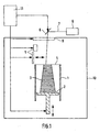
- Fig. 1 shows a laser sintering device as an embodiment of an apparatus for the layered production of a three-dimensional object.
- the laser sintering device has an upwardly open container 1 with a vertically movable therein in a carrier 2, which carries the object 3 to be formed.
- the carrier 2 is adjusted in the vertical direction so that the respective layer of the object to be consolidated lies in a working plane 4.
- an application device 5 for applying the solidifying by electromagnetic radiation powdery building material is provided.
- the device further comprises a laser 6.
- the laser beam 7 generated by the laser 6 is directed by a deflector 8 on a coupling window 9 and from this into the process chamber 10 through and focused at a predetermined point in the working plane 4.
- the coupling window 9 is provided for example in the top wall of the process chamber 10 when the device is arranged so that the laser beam enters the process chamber from above and the object 3 is constructed in the vertical direction.
- the coupling window 9 is made of a material transparent to the laser beam, e.g. Glass or a transparent plastic formed.
- the process chamber 10 may further hold an unillustrated inlet for a gas to maintain a certain atmosphere above the working level, for example, an inlet for an inert gas such as an inert gas. Nitrogen.
- control unit 11 via which the components of the device are controlled in a coordinated manner for carrying out the building process.
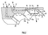
- Fig. 2 shows an enlarged section of the process chamber 10 to the coupling window 9 around in a sectional perspective view.
- the coupling window 9 is formed in the embodiment shown as a rectangular window. It may itself be formed as an optical element such as a lens or as a lens system for focusing the laser beam in the working plane. However, it may also be designed as a protective window permeable to the laser beam for protecting an underlying optical element.
- the coupling window 9 is fastened in a wall section 12 of the cover wall in such a way that it closes off the process chamber in the upper region. It also has a working surface 4 facing surface 9a.
- the wall portion 12 adjacent to a longitudinal side 13 of the coupling window on a first beveled portion 12a, the inclined surface extends at an angle from the coupling window 9 away.
- Adjacent to the chamfered portion 12a there is provided a substantially hollow-cylindrical or hollow-cylinder portion-shaped portion 12b, the cylinder axis of which extends parallel to the longitudinal side 13 of the coupling window.
- the apex 14 of the hollow cylindrical portion is preferably higher than the edge 15 of the chamfered portion 12a, so that the second wall portion 12b has a groove-like structure.
- the sections 12a, 12b extend substantially over the entire longitudinal side 13 of the coupling window, or slightly beyond.
- a first gap 16 is provided, which extends substantially along the longitudinal side of the thirteenth of the coupling window and which is connected to a first inlet bore 17 for a first gas supply.
- the connection with the first gas supply can be made switchable, for example via a valve.
- the first gap 16 has a width and a geometry which is dimensioned such that supplied first gas 18 sweeps substantially tangentially along the surface 9a of the coupling window from the one longitudinal side 13 to the opposite longitudinal side 20.
- the wall section 12 of the process chamber further has, in the region opposite the first gap 16, adjacent to the opposite longitudinal side 20 of the coupling window, a first substantially horizontal wall region 21 and a chamfered region 22 adjoining thereto. This makes it possible for the first gas 18, which flows in through the first gap 16, to strike the entire surface 9a of the coupling-in window substantially tangentially and then be guided away from the coupling-in window by the beveled surface 22.
- a second gap 23 is provided, which extends parallel to the first gap 16 and substantially over the entire longitudinal side 13 of the coupling window or beyond.
- the second gap 23 is connected to a second inlet bore 24 which is connected to a gas supply for a second gas 25.
- the second gas supply can be switched off.
- the second gap 23 is arranged in the hollow-cylinder-section-shaped wall section 12b in a region remote from the coupling window, so that the gas 25 exiting through the gap 23 first flows into the groove formed by the hollow-cylindrical section.
- the second gap 23 is below of the first gap 16, when the coupling window 9 is located in the vertical direction above the working level 4.
- the angle at which the inclined wall portion 12a extends to the hollow cylindrical portion 12b is set so that the beam path is not cropped.
- an unillustrated opening for the discharge of the gas streams is provided, which may be connected to a suction mechanism.
- Nitrogen can be used as first and second gas. But it is also possible to use other gases depending on the application. The first and second gases may also be different from each other.
- the wall sections of the process chamber delimiting the short sides of the coupling-in window can be substantially horizontal so that the gas flows generated by means of the first and second gaps are not swirled by structures.
- a controller which controls the gas flows 18, 25 independently of one another or independently of the flow rate and / or the speed.
- the three-dimensional object is generated layer by layer by solidifying the powdery building material with the laser beam.
- the first gap 16 and the second gap 23 are connected to the gas supply, so that gas flows through the gaps 16, 23 into the process chamber.
- the gas 18 flowing in through the first gap flows tangentially on the surface 9a of the coupling window 9 facing the working plane along and is derived on the opposite side. This allows the gas to prevent access to the surface 9a of the coupling window and thereby keep the surface clean.
- the second gas 25 flowing in through the second gap 23 substantially flows along the inner surface of the hollow cylindrical portion 12b due to the arrangement and formation of the gap 23, and receives, when it touches the edge 15 between the first tapered portion 12a and the hollow cylindrical portion 12b to move, a pulse down towards the working plane. After passing the edge 15, the gas flows at a distance from the surface substantially parallel to the surface 9a. Due to the groove-like configuration of section 12b, the lower gas flow 25 is kept at a distance from the surface of the coupling-in window. As a result, two substantially laminar streams are obtained, which hardly mix with each other.
- the separation of dirt-laden gas can be improved by preventing the gas rising from the working plane, which contains condensates and / or dust particles or other impurities, from the gas flows, to penetrate the optical element. Furthermore, a beam deflection due to a temperature gradient by the lower gas stream 25 is significantly reduced. Thus, both the surface 9a kept sufficiently clean, and minimizes the beam deflection.
- the coupling window does not necessarily have to be rectangular, but may for example also be square, circular or oval or have a different shape. However, the effect is improved if the column for the gas supply and the corresponding sides of the coupling window substantially run parallel.
- the first gap 16 and the second gap 23 are preferably slightly wider than the longitudinal side of the coupling window. However, they may be shorter, but then the coupling window at the edges is not sufficiently covered by gas.
- the shapes of the wall sections 12a and 12b can also be designed differently.
- the chamfered surface 12a may, for example, also be curved into the process chamber.
- the groove-like surface 12b may not necessarily have a cylindrical portion shape, but any other shape may be used which forms a groove for the gas to flow along.
- the invention is also applicable to other devices for the layered production of three-dimensional objects, for example to a laser melting device, in which the powdered, mostly metallic, build-up material is fused by the laser, and to other processing devices, in which gases or vapors occur in a process chamber, which can pollute a coupling window.
Landscapes
- Engineering & Computer Science (AREA)
- Physics & Mathematics (AREA)
- Optics & Photonics (AREA)
- Mechanical Engineering (AREA)
- Plasma & Fusion (AREA)
- Materials Engineering (AREA)
- Chemical & Material Sciences (AREA)
- Manufacturing & Machinery (AREA)
- Toxicology (AREA)
- General Health & Medical Sciences (AREA)
- Health & Medical Sciences (AREA)
- Laser Beam Processing (AREA)
- Powder Metallurgy (AREA)
- Other Surface Treatments For Metallic Materials (AREA)
Applications Claiming Priority (2)
| Application Number | Priority Date | Filing Date | Title |
|---|---|---|---|
| DE102006014694A DE102006014694B3 (de) | 2006-03-28 | 2006-03-28 | Prozesskammer und Verfahren für die Bearbeitung eines Werkstoffs mit einem gerichteten Strahl elektromagnetischer Strahlung, insbesondere für eine Lasersintervorrichtung |
| PCT/EP2007/001390 WO2007112808A1 (de) | 2006-03-28 | 2007-02-16 | Prozesskammer und verfahren für die bearbeitung eines werkstoffs mit einem gerichteten strahl elektromagnetischer strahlung, insbesondere für eine lasersintervorrichtung |
Publications (2)
| Publication Number | Publication Date |
|---|---|
| EP1998929A1 EP1998929A1 (de) | 2008-12-10 |
| EP1998929B1 true EP1998929B1 (de) | 2012-04-04 |
Family
ID=38043035
Family Applications (1)
| Application Number | Title | Priority Date | Filing Date |
|---|---|---|---|
| EP07703516A Active EP1998929B1 (de) | 2006-03-28 | 2007-02-16 | Prozesskammer und verfahren für die bearbeitung eines werkstoffs mit einem gerichteten strahl elektromagnetischer strahlung, insbesondere für eine lasersintervorrichtung |
Country Status (8)
| Country | Link |
|---|---|
| US (1) | US8895893B2 (cg-RX-API-DMAC7.html) |
| EP (1) | EP1998929B1 (cg-RX-API-DMAC7.html) |
| JP (1) | JP2008542550A (cg-RX-API-DMAC7.html) |
| CN (1) | CN101321600B (cg-RX-API-DMAC7.html) |
| BR (1) | BRPI0702860B1 (cg-RX-API-DMAC7.html) |
| DE (1) | DE102006014694B3 (cg-RX-API-DMAC7.html) |
| RU (1) | RU2378094C2 (cg-RX-API-DMAC7.html) |
| WO (1) | WO2007112808A1 (cg-RX-API-DMAC7.html) |
Cited By (1)
| Publication number | Priority date | Publication date | Assignee | Title |
|---|---|---|---|---|
| EP3237177B1 (en) | 2014-12-23 | 2019-05-08 | Renishaw Plc. | Additive manufacturing apparatus |
Families Citing this family (109)
| Publication number | Priority date | Publication date | Assignee | Title |
|---|---|---|---|---|
| DE102006014835A1 (de) * | 2006-03-30 | 2007-10-04 | Fockele, Matthias, Dr. | Vorrichtung zur Herstellung von Gegenständen durch schichtweises Aufbauen aus pulverförmigem Werkstoff |
| EP2231351A4 (en) * | 2007-12-06 | 2012-03-21 | Arcam Ab | APPARATUS AND METHOD FOR MANUFACTURING THREE-DIMENSIONAL OBJECT |
| WO2009084991A1 (en) | 2008-01-03 | 2009-07-09 | Arcam Ab | Method and apparatus for producing three-dimensional objects |
| CN100586611C (zh) * | 2008-02-27 | 2010-02-03 | 华南理工大学 | 定制化舌侧正畸托槽的选区激光熔化直接制造方法 |
| WO2010095987A1 (en) | 2009-02-18 | 2010-08-26 | Arcam Ab | Apparatus for producing a three-dimensional object |
| JP5792720B2 (ja) * | 2009-07-06 | 2015-10-14 | スリーディー システムズ インコーポレーテッド | イメージングアセンブリ |
| US20110122381A1 (en) | 2009-11-25 | 2011-05-26 | Kevin Hickerson | Imaging Assembly |
| RU2507032C2 (ru) | 2009-07-15 | 2014-02-20 | Аркам Аб | Способ и устройство для создания трехмерных объектов |
| DE102009037815B4 (de) * | 2009-08-18 | 2016-06-09 | Sintermask Gmbh | Verfahren und Vorrichtung zur Herstellung eines dreidimensionalen Objektes |
| BR112013009155B1 (pt) | 2011-01-28 | 2018-02-06 | Arcam Ab | Method for production of a three-dimensional body. |
| DE102011003426A1 (de) * | 2011-02-01 | 2012-08-02 | Trumpf Laser- Und Systemtechnik Gmbh | Laserbearbeitungsanlage mit Absaugung |
| EP2797730B2 (en) | 2011-12-28 | 2020-03-04 | Arcam Ab | Method and apparatus for detecting defects in freeform fabrication |
| BR112014012025A2 (pt) | 2011-12-28 | 2017-06-13 | Arcam Ab | método e aparelho para aumentar em artigos tridimencionais cumulativamente fabricados |
| CN104066536B (zh) | 2011-12-28 | 2016-12-14 | 阿卡姆股份公司 | 用于制造多孔三维物品的方法 |
| CN102528034B (zh) * | 2012-02-24 | 2016-05-04 | 湖南华曙高科技有限责任公司 | 一种选择性激光烧结窗口镜气帘保护方法 |
| US9126167B2 (en) | 2012-05-11 | 2015-09-08 | Arcam Ab | Powder distribution in additive manufacturing |
| CN104781022B (zh) | 2012-11-06 | 2017-10-17 | 阿卡姆股份公司 | 用于加成制造的粉末预处理 |
| DE112013006045T5 (de) | 2012-12-17 | 2015-09-17 | Arcam Ab | Additives Herstellungsverfahren und Vorrichtung |
| WO2014095208A1 (en) | 2012-12-17 | 2014-06-26 | Arcam Ab | Method and apparatus for additive manufacturing |
| ES2670977T3 (es) | 2013-02-14 | 2018-06-04 | Renishaw Plc. | Aparato de solidificación selectiva por láser y método |
| EP2969486B1 (en) | 2013-03-15 | 2018-05-09 | 3D Systems, Inc. | Improved powder distribution for laser sintering systems |
| US9669583B2 (en) | 2013-03-15 | 2017-06-06 | Renishaw Plc | Selective laser solidification apparatus and method |
| DE102013205724A1 (de) | 2013-03-28 | 2014-10-02 | Eos Gmbh Electro Optical Systems | Verfahren und Vorrichtung zum Herstellen eines dreidimensionalen Objekts |
| US9550207B2 (en) | 2013-04-18 | 2017-01-24 | Arcam Ab | Method and apparatus for additive manufacturing |
| US9676031B2 (en) | 2013-04-23 | 2017-06-13 | Arcam Ab | Method and apparatus for forming a three-dimensional article |
| US9415443B2 (en) | 2013-05-23 | 2016-08-16 | Arcam Ab | Method and apparatus for additive manufacturing |
| US10335901B2 (en) * | 2013-06-10 | 2019-07-02 | Renishaw Plc | Selective laser solidification apparatus and method |
| GB201310398D0 (en) | 2013-06-11 | 2013-07-24 | Renishaw Plc | Additive manufacturing apparatus and method |
| US9468973B2 (en) | 2013-06-28 | 2016-10-18 | Arcam Ab | Method and apparatus for additive manufacturing |
| US9505057B2 (en) | 2013-09-06 | 2016-11-29 | Arcam Ab | Powder distribution in additive manufacturing of three-dimensional articles |
| US9676032B2 (en) | 2013-09-20 | 2017-06-13 | Arcam Ab | Method for additive manufacturing |
| US10434572B2 (en) | 2013-12-19 | 2019-10-08 | Arcam Ab | Method for additive manufacturing |
| US9802253B2 (en) | 2013-12-16 | 2017-10-31 | Arcam Ab | Additive manufacturing of three-dimensional articles |
| US10130993B2 (en) | 2013-12-18 | 2018-11-20 | Arcam Ab | Additive manufacturing of three-dimensional articles |
| US9789563B2 (en) | 2013-12-20 | 2017-10-17 | Arcam Ab | Method for additive manufacturing |
| US9789541B2 (en) | 2014-03-07 | 2017-10-17 | Arcam Ab | Method for additive manufacturing of three-dimensional articles |
| DE102014205875A1 (de) | 2014-03-28 | 2015-10-01 | Eos Gmbh Electro Optical Systems | Vorrichtung und Verfahren zum schichtweisen Herstellen eines dreidimensionalen Objekts |
| US20150283613A1 (en) | 2014-04-02 | 2015-10-08 | Arcam Ab | Method for fusing a workpiece |
| GB201410484D0 (en) | 2014-06-12 | 2014-07-30 | Renishaw Plc | Additive manufacturing apparatus and a flow device for use with such apparatus |
| EP3157696A4 (en) | 2014-06-20 | 2018-09-05 | VELO3D, Inc. | Apparatuses, systems and methods for three-dimensional printing |
| US9310188B2 (en) | 2014-08-20 | 2016-04-12 | Arcam Ab | Energy beam deflection speed verification |
| GB201418595D0 (en) | 2014-10-20 | 2014-12-03 | Renishaw Plc | Additive manufacturing apparatus and methods |
| US20160167303A1 (en) | 2014-12-15 | 2016-06-16 | Arcam Ab | Slicing method |
| US9721755B2 (en) | 2015-01-21 | 2017-08-01 | Arcam Ab | Method and device for characterizing an electron beam |
| GB201505458D0 (en) | 2015-03-30 | 2015-05-13 | Renishaw Plc | Additive manufacturing apparatus and methods |
| US11014161B2 (en) | 2015-04-21 | 2021-05-25 | Arcam Ab | Method for additive manufacturing |
| CN118080891A (zh) | 2015-07-23 | 2024-05-28 | 瑞尼斯豪公司 | 增材制造设备和用于此类设备的气体流动装置 |
| CN104959605B (zh) * | 2015-07-27 | 2017-10-10 | 中南大学 | 一种制备镁合金人工骨的激光选区熔覆设备 |
| US10807187B2 (en) | 2015-09-24 | 2020-10-20 | Arcam Ab | X-ray calibration standard object |
| US11571748B2 (en) | 2015-10-15 | 2023-02-07 | Arcam Ab | Method and apparatus for producing a three-dimensional article |
| WO2017079091A1 (en) | 2015-11-06 | 2017-05-11 | Velo3D, Inc. | Adept three-dimensional printing |
| US10525531B2 (en) | 2015-11-17 | 2020-01-07 | Arcam Ab | Additive manufacturing of three-dimensional articles |
| US10610930B2 (en) | 2015-11-18 | 2020-04-07 | Arcam Ab | Additive manufacturing of three-dimensional articles |
| US10286603B2 (en) | 2015-12-10 | 2019-05-14 | Velo3D, Inc. | Skillful three-dimensional printing |
| DE102015121748B4 (de) * | 2015-12-14 | 2025-09-11 | Concept Laser Gmbh | Strömungseinrichtung für eine Vorrichtung zur generativen Herstellung eines dreidimensionalen Objekts, Vorrichtung mit einer solchen Strömungseinrichtung und Verfahren zur Herstellung eines dreidimensionalen Objekts unter Verwendung einer Vorrichtung und einer entsprechenden Strömungseinrichtung |
| US9919360B2 (en) | 2016-02-18 | 2018-03-20 | Velo3D, Inc. | Accurate three-dimensional printing |
| JP6653473B2 (ja) * | 2016-03-11 | 2020-02-26 | パナソニックIpマネジメント株式会社 | 三次元形状造形物の製造装置 |
| US11247274B2 (en) | 2016-03-11 | 2022-02-15 | Arcam Ab | Method and apparatus for forming a three-dimensional article |
| US10549348B2 (en) | 2016-05-24 | 2020-02-04 | Arcam Ab | Method for additive manufacturing |
| US11325191B2 (en) | 2016-05-24 | 2022-05-10 | Arcam Ab | Method for additive manufacturing |
| US10525547B2 (en) | 2016-06-01 | 2020-01-07 | Arcam Ab | Additive manufacturing of three-dimensional articles |
| US10286452B2 (en) | 2016-06-29 | 2019-05-14 | Velo3D, Inc. | Three-dimensional printing and three-dimensional printers |
| US11691343B2 (en) | 2016-06-29 | 2023-07-04 | Velo3D, Inc. | Three-dimensional printing and three-dimensional printers |
| US10307803B2 (en) * | 2016-07-20 | 2019-06-04 | The United States Of America As Represented By Secretary Of The Navy | Transmission window cleanliness for directed energy devices |
| WO2018064349A1 (en) | 2016-09-30 | 2018-04-05 | Velo3D, Inc. | Three-dimensional objects and their formation |
| US10792757B2 (en) | 2016-10-25 | 2020-10-06 | Arcam Ab | Method and apparatus for additive manufacturing |
| US20180126462A1 (en) | 2016-11-07 | 2018-05-10 | Velo3D, Inc. | Gas flow in three-dimensional printing |
| DE102016121490A1 (de) * | 2016-11-10 | 2018-05-17 | Trumpf Laser- Und Systemtechnik Gmbh | Homogene absaugung bei der generativen fertigung |
| US10987752B2 (en) | 2016-12-21 | 2021-04-27 | Arcam Ab | Additive manufacturing of three-dimensional articles |
| US20180186081A1 (en) | 2017-01-05 | 2018-07-05 | Velo3D, Inc. | Optics in three-dimensional printing |
| DE102017104351A1 (de) | 2017-03-02 | 2018-09-06 | Cl Schutzrechtsverwaltungs Gmbh | Vorrichtung zur additiven Herstellung dreidimensionaler Objekte |
| US10442003B2 (en) | 2017-03-02 | 2019-10-15 | Velo3D, Inc. | Three-dimensional printing of three-dimensional objects |
| US20180281284A1 (en) | 2017-03-28 | 2018-10-04 | Velo3D, Inc. | Material manipulation in three-dimensional printing |
| DE102017206792A1 (de) * | 2017-04-21 | 2018-10-25 | Eos Gmbh Electro Optical Systems | Vorrichtung und Verfahren zum generativen Herstellen eines dreidimensionalen Objekts |
| US11059123B2 (en) | 2017-04-28 | 2021-07-13 | Arcam Ab | Additive manufacturing of three-dimensional articles |
| US11292062B2 (en) | 2017-05-30 | 2022-04-05 | Arcam Ab | Method and device for producing three-dimensional objects |
| BE1025304B1 (nl) * | 2017-06-06 | 2019-01-17 | Layerwise N.V. | Werkwijze en inrichting voor het reinigen en/of het vervangen van een laservenster van een proceskamer |
| CN107322925B (zh) * | 2017-08-16 | 2019-10-15 | 湖南华曙高科技有限责任公司 | 吹扫装置及光固化成型设备 |
| US11185926B2 (en) | 2017-09-29 | 2021-11-30 | Arcam Ab | Method and apparatus for additive manufacturing |
| US20190099943A1 (en) * | 2017-10-03 | 2019-04-04 | General Electric Company | Additive manufacturing method and apparatus |
| US10529070B2 (en) | 2017-11-10 | 2020-01-07 | Arcam Ab | Method and apparatus for detecting electron beam source filament wear |
| US10821721B2 (en) | 2017-11-27 | 2020-11-03 | Arcam Ab | Method for analysing a build layer |
| US11072117B2 (en) | 2017-11-27 | 2021-07-27 | Arcam Ab | Platform device |
| US12350754B2 (en) | 2017-12-22 | 2025-07-08 | Arcam Ab | Electron beam source and the use of the same |
| US11517975B2 (en) | 2017-12-22 | 2022-12-06 | Arcam Ab | Enhanced electron beam generation |
| US10272525B1 (en) | 2017-12-27 | 2019-04-30 | Velo3D, Inc. | Three-dimensional printing systems and methods of their use |
| US10144176B1 (en) | 2018-01-15 | 2018-12-04 | Velo3D, Inc. | Three-dimensional printing systems and methods of their use |
| US11267051B2 (en) | 2018-02-27 | 2022-03-08 | Arcam Ab | Build tank for an additive manufacturing apparatus |
| US10800101B2 (en) | 2018-02-27 | 2020-10-13 | Arcam Ab | Compact build tank for an additive manufacturing apparatus |
| US11400519B2 (en) | 2018-03-29 | 2022-08-02 | Arcam Ab | Method and device for distributing powder material |
| US10814430B2 (en) | 2018-04-09 | 2020-10-27 | General Electric Company | Systems and methods for additive manufacturing flow control devices |
| CN108422661B (zh) * | 2018-05-09 | 2024-02-23 | 苏州倍丰智能科技有限公司 | 增材制造设备 |
| CN108407292A (zh) * | 2018-05-11 | 2018-08-17 | 上海联泰科技股份有限公司 | 3d打印设备及其气体循环装置 |
| US11203027B2 (en) * | 2018-08-21 | 2021-12-21 | General Electric Company | Lower gas flow injection system and method for additive manufacturing system |
| US11298716B2 (en) * | 2018-08-21 | 2022-04-12 | General Electric Company | Flow directing system and method for additive manufacturing system |
| DE102018127063A1 (de) | 2018-10-30 | 2020-04-30 | Bayerische Motoren Werke Aktiengesellschaft | Verfahren zur additiven Herstellung eines Objekts |
| DE102018219305A1 (de) * | 2018-11-12 | 2020-05-14 | Eos Gmbh Electro Optical Systems | Beströmungsvorrichtung und Beströmungsverfahren für eine Vorrichtung zum additiven Herstellen eines dreidimensionalen Objekts |
| FR3089851B1 (fr) * | 2018-12-12 | 2020-12-18 | Addup | Chambre de fabrication pour une machine de fabrication additive |
| CA3148849A1 (en) | 2019-07-26 | 2021-02-04 | Velo3D, Inc. | Quality assurance in formation of three-dimensional objects |
| GB201913628D0 (en) * | 2019-09-20 | 2019-11-06 | Alltec Angewandte Laserlicht Tech Gmbh | Housing for a head for directing an electromagnetic radiation beam at a target |
| US11400649B2 (en) * | 2019-09-26 | 2022-08-02 | Applied Materials, Inc. | Air knife assembly for additive manufacturing |
| US11413817B2 (en) | 2019-09-26 | 2022-08-16 | Applied Materials, Inc. | Air knife inlet and exhaust for additive manufacturing |
| FR3102397B1 (fr) | 2019-10-24 | 2022-10-14 | Addup | Machine à faisceau laser comprenant un dispositif d’application d’une couche de gel optique sur une vitre traversée par le faisceau laser. |
| EP4061973A1 (en) * | 2019-11-18 | 2022-09-28 | EOS GmbH Electro Optical Systems | Weldable aluminium alloys comprising zn as main alloying element for direct metal laser sintering |
| CN111745161A (zh) * | 2020-07-21 | 2020-10-09 | 南京前知智能科技有限公司 | 一种双粉快速切换型选择性激光熔融设备 |
| DE102020129413A1 (de) | 2020-11-09 | 2022-05-12 | Trumpf Laser- Und Systemtechnik Gmbh | Verfahren und Vorrichtung zur Herstellung von dreidimensionalen Objekten durch selektives Verfestigen eines schichtweise aufgebrachten Aufbaumaterials |
| JP6915145B1 (ja) | 2020-12-17 | 2021-08-04 | 株式会社ソディック | 積層造形装置 |
| RU205057U1 (ru) * | 2021-02-16 | 2021-06-24 | Сергей Дмитриевич Игошин | Устройство локальной защитной камеры с инертной средой для печати активных металлов аддитивным методом прямой подачи материала в зону плавления |
| FR3143417B1 (fr) | 2022-12-15 | 2025-02-14 | Addup | Machine de fabrication additive comprenant un système de remplacement d’une vitre équipant une paroi de l’enceinte de fabrication. |
Family Cites Families (21)
| Publication number | Priority date | Publication date | Assignee | Title |
|---|---|---|---|---|
| FR2499297A1 (fr) | 1981-01-30 | 1982-08-06 | Commissariat Energie Atomique | Traversee etanche de la paroi d'une cellule chaude par un faisceau laser et son procede d'utilisation |
| JPH03177699A (ja) * | 1989-12-05 | 1991-08-01 | Tlv Co Ltd | フリーフロート式トラップ |
| AU9065991A (en) | 1990-11-09 | 1992-06-11 | Dtm Corporation | Controlled gas flow for selective laser sintering |
| JPH05192782A (ja) | 1992-01-21 | 1993-08-03 | Fanuc Ltd | レーザ加工装置 |
| US5393482A (en) * | 1993-10-20 | 1995-02-28 | United Technologies Corporation | Method for performing multiple beam laser sintering employing focussed and defocussed laser beams |
| NZ272635A (en) | 1994-08-02 | 1998-02-26 | Mcneil Ppc Inc | Laser cutting/drilling processing head that creates a vortex gas flow within the head to clean and prevent back spatting of particles onto the lens therein |
| JP3119090B2 (ja) * | 1994-10-05 | 2000-12-18 | 株式会社日立製作所 | 水中レーザ加工装置及びその装置を用いた水中施工方法 |
| DE29513026U1 (de) * | 1995-08-16 | 1995-10-05 | Eos Electro Optical Syst | Vorrichtung zur schichtweisen Herstellung eines Objektes mittels Lasersintern |
| TW320586B (cg-RX-API-DMAC7.html) * | 1995-11-24 | 1997-11-21 | Hitachi Ltd | |
| DE19649865C1 (de) * | 1996-12-02 | 1998-02-12 | Fraunhofer Ges Forschung | Verfahren zur Herstellung eines Formkörpers |
| GB9702658D0 (en) * | 1997-02-10 | 1997-04-02 | Imperial College | Fabrication method and apparatus |
| JPH11267876A (ja) | 1998-03-23 | 1999-10-05 | Sumitomo Heavy Ind Ltd | レーザ加工用ノズル |
| DE19853947C1 (de) | 1998-11-23 | 2000-02-24 | Fraunhofer Ges Forschung | Prozeßkammer für das selektive Laser-Schmelzen |
| JP2000214286A (ja) | 1999-01-27 | 2000-08-04 | Mitsubishi Nuclear Fuel Co Ltd | 支持格子溶接装置 |
| JP2000263276A (ja) * | 1999-03-16 | 2000-09-26 | Sekisui Chem Co Ltd | レーザー加工ヘッド |
| EP1149660A1 (en) | 2000-04-03 | 2001-10-31 | Rexam Beverage Packaging AB | Method and device for dust protection in a laser processing apparatus |
| JP2002192374A (ja) | 2000-12-22 | 2002-07-10 | Sumitomo Heavy Ind Ltd | レーザ加工ヘッド |
| US8062020B2 (en) | 2003-02-25 | 2011-11-22 | Panasonic Electric Works Co., Ltd. | Three dimensional structure producing device and producing method |
| JP2004277878A (ja) * | 2003-02-25 | 2004-10-07 | Matsushita Electric Works Ltd | 三次元形状造形物の製造装置及び製造方法 |
| JP2005217119A (ja) | 2004-01-29 | 2005-08-11 | Matsushita Electric Ind Co Ltd | レーザ発振装置 |
| CN1295051C (zh) * | 2004-12-15 | 2007-01-17 | 华中科技大学 | 一种直接制造金属零件的快速成形系统 |
-
2006
- 2006-03-28 DE DE102006014694A patent/DE102006014694B3/de not_active Expired - Fee Related
-
2007
- 2007-02-16 US US11/886,102 patent/US8895893B2/en active Active
- 2007-02-16 BR BRPI0702860-1A patent/BRPI0702860B1/pt not_active IP Right Cessation
- 2007-02-16 WO PCT/EP2007/001390 patent/WO2007112808A1/de not_active Ceased
- 2007-02-16 JP JP2008515230A patent/JP2008542550A/ja active Pending
- 2007-02-16 EP EP07703516A patent/EP1998929B1/de active Active
- 2007-02-16 RU RU2008112291/02A patent/RU2378094C2/ru active
- 2007-02-16 CN CN2007800005234A patent/CN101321600B/zh active Active
Cited By (1)
| Publication number | Priority date | Publication date | Assignee | Title |
|---|---|---|---|---|
| EP3237177B1 (en) | 2014-12-23 | 2019-05-08 | Renishaw Plc. | Additive manufacturing apparatus |
Also Published As
| Publication number | Publication date |
|---|---|
| US20090266803A1 (en) | 2009-10-29 |
| US8895893B2 (en) | 2014-11-25 |
| RU2378094C2 (ru) | 2010-01-10 |
| BRPI0702860B1 (pt) | 2015-06-09 |
| CN101321600A (zh) | 2008-12-10 |
| DE102006014694B3 (de) | 2007-10-31 |
| BRPI0702860A (pt) | 2008-04-01 |
| WO2007112808A1 (de) | 2007-10-11 |
| EP1998929A1 (de) | 2008-12-10 |
| CN101321600B (zh) | 2012-08-29 |
| HK1124282A1 (en) | 2009-07-10 |
| JP2008542550A (ja) | 2008-11-27 |
| RU2008112291A (ru) | 2009-10-10 |
Similar Documents
| Publication | Publication Date | Title |
|---|---|---|
| EP1998929B1 (de) | Prozesskammer und verfahren für die bearbeitung eines werkstoffs mit einem gerichteten strahl elektromagnetischer strahlung, insbesondere für eine lasersintervorrichtung | |
| EP3174691B1 (de) | Verfahren, vorrichtung und steuereinheit zum herstellen eines dreidimensionalen objekts | |
| WO2000030789A1 (de) | Prozesskammer für das selektive laser-schmelzen | |
| DE102015116923A1 (de) | 3D-Drucker | |
| DE102019103250B4 (de) | Laserbearbeitungskopf, bei dem eine Verschmutzung des Schutzfensters unterdrückt wird | |
| EP3620245B1 (de) | Beströmungsverfahren für eine additive herstellvorrichtung | |
| DE102010052206A1 (de) | Vorrichtung zum Herstellen von dreidimensionalen Objekten | |
| DE102018210260A1 (de) | Vorrichtung und Verfahren zum generativen Herstellen eines dreidimensionalen Objekts | |
| DE102014212100A1 (de) | Generatives Herstellungsverfahren und Vorrichtung hierzu mit entgegengesetzt gerichteten Schutzgasströmen | |
| DE102018129022A1 (de) | Radiale Strömung über ein Baufeld | |
| EP3706939B1 (de) | Absaugung bei der generativen fertigung | |
| EP1394283A1 (de) | Verfahren und Vorrichtung zur grossflächigen Beschichtung von Substraten bei Atmosphärendruckbedingungen | |
| DE112019007022B4 (de) | Schutzgasdüse zur Metallbildung und Lasermetallbildungsvorrichtung | |
| WO2017081293A1 (de) | Verfahren und vorrichtung zum herstellen eines dreidimensionalen objekts | |
| EP3290183A1 (de) | Verfahren und vorrichtung zum generativen herstellen eines dreidimensionalen objekts | |
| EP3377236B1 (de) | Vorrichtung zur generativen herstellung eines dreidimensionalen objekts | |
| EP3323597B1 (de) | Vorrichtung und verfahren zur additiven herstellung eines dreidimensionalen produktes | |
| WO2020048798A1 (de) | Vorrichtung und verfahren zum additiven herstellen eines dreidimensionalen objekts | |
| EP3212354B1 (de) | Vorrichtung und verfahren zur generativen herstellung zumindest eines bauteilbereichs eines bauteils | |
| WO2020043419A1 (de) | Schichtbauvorrichtung zur additiven herstellung zumindest eines bauteilbereichs eines bauteils, verfahren zum betreiben einer solchen schichtbauvorrichtung und speichermedium | |
| EP3880389B1 (de) | Pulverauftragsvorrichtung, verfahren zum betreiben einer pulverauftragsvorrichtung und anlage zur herstellung eines dreidimensionalen werkstücks | |
| WO2024223592A1 (de) | Vorrichtung und verfahren zur gerichteten gasbeaufschlagung eines bauraums zur additiven fertigung | |
| EP3322548A1 (de) | Vakuum sls verfahren zur additiven herstellung von metallischen bauteilen | |
| DE69402742T2 (de) | Vorrichtung zur Verteilung von pulverförmigen Feststoffen auf ein Substrat zum Zweck seiner Beschichtung | |
| DE4224886C2 (de) | Oberflächenbeschichtungsvorrichtung |
Legal Events
| Date | Code | Title | Description |
|---|---|---|---|
| PUAI | Public reference made under article 153(3) epc to a published international application that has entered the european phase |
Free format text: ORIGINAL CODE: 0009012 |
|
| 17P | Request for examination filed |
Effective date: 20071120 |
|
| AK | Designated contracting states |
Kind code of ref document: A1 Designated state(s): DE FR GB IT |
|
| 17Q | First examination report despatched |
Effective date: 20090122 |
|
| RBV | Designated contracting states (corrected) |
Designated state(s): DE FR GB IT |
|
| GRAP | Despatch of communication of intention to grant a patent |
Free format text: ORIGINAL CODE: EPIDOSNIGR1 |
|
| DAX | Request for extension of the european patent (deleted) | ||
| GRAS | Grant fee paid |
Free format text: ORIGINAL CODE: EPIDOSNIGR3 |
|
| GRAA | (expected) grant |
Free format text: ORIGINAL CODE: 0009210 |
|
| AK | Designated contracting states |
Kind code of ref document: B1 Designated state(s): DE FR GB IT |
|
| REG | Reference to a national code |
Ref country code: GB Ref legal event code: FG4D Free format text: NOT ENGLISH |
|
| REG | Reference to a national code |
Ref country code: DE Ref legal event code: R096 Ref document number: 502007009610 Country of ref document: DE Effective date: 20120531 |
|
| PLBI | Opposition filed |
Free format text: ORIGINAL CODE: 0009260 |
|
| PLAX | Notice of opposition and request to file observation + time limit sent |
Free format text: ORIGINAL CODE: EPIDOSNOBS2 |
|
| 26 | Opposition filed |
Opponent name: CL SCHUTZRECHTSVERWALTUNGS GMBH Effective date: 20121228 |
|
| REG | Reference to a national code |
Ref country code: DE Ref legal event code: R026 Ref document number: 502007009610 Country of ref document: DE Effective date: 20121228 |
|
| PLBP | Opposition withdrawn |
Free format text: ORIGINAL CODE: 0009264 |
|
| PLAF | Information modified related to communication of a notice of opposition and request to file observations + time limit |
Free format text: ORIGINAL CODE: EPIDOSCOBS2 |
|
| PLBB | Reply of patent proprietor to notice(s) of opposition received |
Free format text: ORIGINAL CODE: EPIDOSNOBS3 |
|
| PLBD | Termination of opposition procedure: decision despatched |
Free format text: ORIGINAL CODE: EPIDOSNOPC1 |
|
| PLBM | Termination of opposition procedure: date of legal effect published |
Free format text: ORIGINAL CODE: 0009276 |
|
| STAA | Information on the status of an ep patent application or granted ep patent |
Free format text: STATUS: OPPOSITION PROCEDURE CLOSED |
|
| 27C | Opposition proceedings terminated |
Effective date: 20130927 |
|
| REG | Reference to a national code |
Ref country code: FR Ref legal event code: PLFP Year of fee payment: 10 |
|
| REG | Reference to a national code |
Ref country code: FR Ref legal event code: PLFP Year of fee payment: 11 |
|
| REG | Reference to a national code |
Ref country code: FR Ref legal event code: PLFP Year of fee payment: 12 |
|
| P01 | Opt-out of the competence of the unified patent court (upc) registered |
Effective date: 20230525 |
|
| PGFP | Annual fee paid to national office [announced via postgrant information from national office to epo] |
Ref country code: DE Payment date: 20250722 Year of fee payment: 19 |
|
| PGFP | Annual fee paid to national office [announced via postgrant information from national office to epo] |
Ref country code: IT Payment date: 20250724 Year of fee payment: 19 |
|
| PGFP | Annual fee paid to national office [announced via postgrant information from national office to epo] |
Ref country code: GB Payment date: 20250722 Year of fee payment: 19 |
|
| PGFP | Annual fee paid to national office [announced via postgrant information from national office to epo] |
Ref country code: FR Payment date: 20250722 Year of fee payment: 19 |