EP1998018B1 - Kühlgebläsesteuerung und kühlgebläsesteuerung für maschinenbetrieb - Google Patents
Kühlgebläsesteuerung und kühlgebläsesteuerung für maschinenbetrieb Download PDFInfo
- Publication number
- EP1998018B1 EP1998018B1 EP07738059.0A EP07738059A EP1998018B1 EP 1998018 B1 EP1998018 B1 EP 1998018B1 EP 07738059 A EP07738059 A EP 07738059A EP 1998018 B1 EP1998018 B1 EP 1998018B1
- Authority
- EP
- European Patent Office
- Prior art keywords
- revolving speed
- temperature
- cooling fan
- difference
- oil
- Prior art date
- Legal status (The legal status is an assumption and is not a legal conclusion. Google has not performed a legal analysis and makes no representation as to the accuracy of the status listed.)
- Active
Links
Images


Classifications
-
- E—FIXED CONSTRUCTIONS
- E02—HYDRAULIC ENGINEERING; FOUNDATIONS; SOIL SHIFTING
- E02F—DREDGING; SOIL-SHIFTING
- E02F9/00—Component parts of dredgers or soil-shifting machines, not restricted to one of the kinds covered by groups E02F3/00 - E02F7/00
- E02F9/20—Drives; Control devices
- E02F9/22—Hydraulic or pneumatic drives
- E02F9/226—Safety arrangements, e.g. hydraulic driven fans, preventing cavitation, leakage, overheating
-
- F—MECHANICAL ENGINEERING; LIGHTING; HEATING; WEAPONS; BLASTING
- F01—MACHINES OR ENGINES IN GENERAL; ENGINE PLANTS IN GENERAL; STEAM ENGINES
- F01P—COOLING OF MACHINES OR ENGINES IN GENERAL; COOLING OF INTERNAL-COMBUSTION ENGINES
- F01P2025/00—Measuring
- F01P2025/08—Temperature
- F01P2025/13—Ambient temperature
-
- F—MECHANICAL ENGINEERING; LIGHTING; HEATING; WEAPONS; BLASTING
- F01—MACHINES OR ENGINES IN GENERAL; ENGINE PLANTS IN GENERAL; STEAM ENGINES
- F01P—COOLING OF MACHINES OR ENGINES IN GENERAL; COOLING OF INTERNAL-COMBUSTION ENGINES
- F01P2025/00—Measuring
- F01P2025/08—Temperature
- F01P2025/34—Heat exchanger incoming fluid temperature
-
- F—MECHANICAL ENGINEERING; LIGHTING; HEATING; WEAPONS; BLASTING
- F01—MACHINES OR ENGINES IN GENERAL; ENGINE PLANTS IN GENERAL; STEAM ENGINES
- F01P—COOLING OF MACHINES OR ENGINES IN GENERAL; COOLING OF INTERNAL-COMBUSTION ENGINES
- F01P7/00—Controlling of coolant flow
- F01P7/02—Controlling of coolant flow the coolant being cooling-air
- F01P7/04—Controlling of coolant flow the coolant being cooling-air by varying pump speed, e.g. by changing pump-drive gear ratio
Definitions
- the present invention relates to a controller, for controlling the revolving speed (number of revolutions) of a cooling fan, which is suitable for use in a cooling fan mounted in working machinery such as a hydraulic shovel.
- Cooling fans are normally designed, taking a severe operating environment into account. For example, even when the air temperature is high such as 30°C and an engine runs continuously in a condition of maximum load such as full throttle, the cooling ability of cooling equipments is raised by increasing the revolving speed of the cooling fan to admit a cooling wind at a higher volume into the cooling equipments so that the engine is not overheated.
- the revolving speed of the cooling fan is increased, the rotational resistance due to air will become great, and wind noise by revolution of the cooling fan will be increased. This will have a great influence on the generation of noise.
- the revolving speed of a cooling fan is being controlled according to the temperature of hydraulic operating oil employed for the operation and travel of working machinery.
- construction machinery discloses a technique that controls the revolving speed of a cooling fan by a fan controller in accordance with the temperature (water temperature) T w of engine-cooling water and the temperature (oil temperature) T o of the hydraulic operating oil circulating through a hydraulic system.
- the water temperature T w is detected by a water-temperature sensor
- the oil temperature T o is detected by an oil-temperature sensor.
- the cooling fan is not operated.
- the water temperature T w is between the first temperature Tw 1 and a second temperature Tw 2 higher than the first temperature Tw 1 and the oil temperature T o is smaller than the first temperature To 1
- the cooling fan is operated at low speeds.
- engine load i.e., the generation of heat of an engine
- engine load is also affected by factors other than oil temperature and water temperature. It is known that the cooling ability of the cooling equipments for cooling hydraulic operating oil or engine-cooling water is proportional to the temperature and volume of a cooling wind admitted by a cooling fan. That is, the cooler the cooling wind is and higher the wind volume is, the more efficiently the hydraulic operating oil or engine-cooling water is cooled.
- oil temperature continues to hold about 70°C when the temperature of the cooling wind is as low as 0°C.
- oil temperature continues to hold about 70°C when the temperature of the cooling wind is as high as 30°C. That is, there is a situation where oil temperature holds the same temperature though the cooling abilities by the cooling wind differ.
- the former situation means that the heating value of the hydraulic operating oil is large, i. e. , it means that great work is performed on the hydraulic operating oil and thus the engine load is high.
- the latter situation means the heating value of the hydraulic operating oil is small, i.e., it means that little work is performed on the hydraulic operating oil and thus the engine load is low. For that reason, although the former situation is better in cooling ability than the latter situation, the hydraulic operating oil is cooled down to only the same oil temperature as that in the latter situation.
- the present invention has been made in view of the problems described above. Accordingly, it is an obj ect of the present invention to provide a cooling fan controller and a cooling fan controller for working machinery that optimally control the revolving speed of the cooling fan in accordance with load to suppress noise caused by the cooling fan.
- a cooling fan controller for controlling a revolving speed of a cooling fan that introduces outside air as a cooling wind to cool a fluid being cooled.
- the cooling fan controller includes a fluid temperature sensor for sensing a temperature of the fluid; an air temperature sensor for sensing a temperature of the air; and control means for calculating a difference between the fluid temperature sensed by the fluid temperature sensor and the air temperature sensed by the air temperature sensor, and setting a target revolving speed of the cooling fan in accordance with a magnitude of the calculated difference.
- the cooling fan controller of the present invention as set forth in claim 2 is characterized in that, in the controller as set forth in claim 1, the difference has a first reference difference and a second reference difference greater than the first reference difference as reference values; the target revolving speed has a first minimum revolving speed as a first lower limit value and has a first maximum revolving speed as a first upper limit value; and the control means if the difference is less than or equal to the first reference difference, sets the target revolving speed at the first minimum revolving speed, if the difference is greater than the second reference difference, sets the target revolving speed at the first maximum revolving speed, and if the difference is greater than the first reference difference and less than or equal to the second reference difference, sets the target revolving speed at a revolving speed linearly interpolated between the first minimum revolving speed and the first maximum revolving speed in accordance with a magnitude of the difference.
- the cooling fan controller of the present invention as set forth in claim 3 is characterized in that, in the controller as set forth in claim 2, the fluid temperature has a first reference fluid temperature and a second reference fluid temperature greater than the first reference fluid temperature as reference values; the target revolving speed further has a second minimum revolving speed as a second lower limit value and further has a second maximum revolving speed as a second upper limit value; and the control means if the fluid temperature is less than or equal to the first reference fluid temperature, sets the target revolving speed at the second minimum revolving speed, if the fluid temperature is greater than the second reference fluid temperature, sets the target revolving speed at the second maximum revolving speed, and if the fluid temperature is greater than the first reference fluid temperature and less than or equal to the second reference fluid temperature, sets the target revolving speed at a revolving speed linearly interpolated between the second minimum revolving speed and the second maximum revolving speed in accordance with the magnitude of the fluid temperature, and sets, as
- the cooling fan controller for working machinery of the present invention as set forth in claim 4 is characterized in that the cooling fan controller as set forth in any of claims 1 through 3 is applicable to working machinery.
- the cooling fan controller for working machinery of the present invention as set forth in claim 5 is characterized in that, in the cooling fan controller for working machinery as set forth in claim 4, the fluid is hydraulic operating oil employed for operation and travel of the working machinery.
- the cooling fan controller of the present invention in controlling the revolving speed of the cooling fan, the difference between the temperature of the fluid and the temperature of the air is employed, so a load on a driving source (e. g. , a driving source for the cooling fan) that performs work on the fluid can be properly determined. Since the target revolving speed of the cooling fan is set according to the determined load, the revolving speed of the cooling fan can be finely and optimally controlled. Accordingly, because the cooling fan is not rotated to more than necessity, machine noise that is generated by the cooling fan can be suppressed.
- a driving source e. g. , a driving source for the cooling fan
- a target revolving speed is set at a revolving speed linearly interpolated according to the magnitude of the difference between the fluid temperature and the air temperature, so the revolving speed of the cooling fan can be more finely controlled.
- the target revolving speed has an upper limit value and a lower limit value, and if the difference is less than or equal to the first reference difference, the target revolving speed is set at the first minimum revolving speed. Further, if the difference is greater than the second reference difference, the target revolving speed is set at the first maximum revolving speed. Therefore, with the cooling ability being sufficiently ensured, noise can be suppressed, and fuel consumption can be improved.
- the greater one of the target revolving speed based on the difference between the fluid temperature and the air temperature and the target revolving speed based on the fluid temperature is determined as a final target revolving speed, so the revolving speed of the cooling fan can be more finely controlled. Therefore, with the cooling ability being sufficiently ensured, noise can be suppressed, and fuel consumption can be improved.
- the revolving speed of the cooling fan mounted in working machinery can be optimally controlled.
- the cooling fan is driven by an engine that is a power source for working machinery, it is possible to reduce extra engine output that is consumed for driving the cooling fan.
- the cooling fan controller for working machinery of the present invention as set forth in claim 5 the temperature of hydraulic operating oil on which a load on a machine body is easily reflected is employed, so a load on the engine can be determined with a high degree of accuracy.
- FIGS. 1 to 6 show a cooling fan controller in accordance with the preferred embodiment of the present invention.
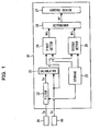
- FIG. 1 is a block diagram showing the controller
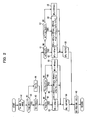
- FIG. 2 is a flowchart showing the contents of control which is performed by the controller
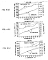
- FIGS. 3 (a) 'and 3 (b) are graphs showing the revolving speed (target revolving speed) of the cooling fan that is set by the controller
- FIG. 3 (c) is a graph showing the revolving speed of the cooling fan that is set by a conventional cooling fan controller that employs only oil temperature information.
- FIGS. 4(a) to 4(c) are graphs showing the revolving speed of the cooling fan versus oil temperature, obtained by the experimental results controlled by the cooling fan controller and conventional controller
- FIG. 4(a) to 4(c) are graphs showing the revolving speed of the cooling fan versus oil temperature, obtained by the experimental results controlled by the cooling fan controller and conventional controller
- FIG. 1 is a block diagram showing the controller
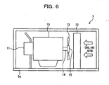
- FIG. 5 is a perspective view showing a hydraulic shovel equipped with the cooling fan controller; and FIG. 6 is a sectional view taken along line A-A of FIG. 5 . Note in FIG. 6 that the sectional areas are shown without hatching.
- the hydraulic shovel 1 is constituted by an under carriage 2, an upper structure (machine body) 3 rotatably connected to the under carriage 2, and a working attachment 4, which extends forward from the upper structure 3.
- the upper structure 3 has a revolving frame 3a as a mount, and a counterweight 5 placed on the rear end portion of the revolving frame 3a for balancing with the working attachment 4.
- the upper structure 3 contains an engine 10, which is a power source for the hydraulic shovel 1, a hydraulic pump 11, which is driven by the engine 10, a cooling equipment 12, such as a radiator in which engine-cooling water is cooled or an oil cooler used to cool hydraulic operating oil(fluid being cooled), a cooling fan 13 by which a cooling wind is introduced to a cooling equipment 12, a hydraulic operating oil tank (not shown), in which hydraulic operating oil is stored, and a controller (control means) 20 (see FIG. 1 ), which sets a target revolving speed (also called a fan revolving speed) N f of the cooling fan 13.
- a target revolving speed also called a fan revolving speed
- the cooling fan 13, in order to be driven by the engine 10, is mounted on the driving shaft 14 (which is the same shaft as the driving shaft of the engine 10) through a viscous clutch (fluid coupling) 15 which is rotation-transmitting means.
- the viscous clutch 15 is a device that exploits the shear of silicon oil whose viscosity is high, for generating torque in accordance with a differential revolving speed.
- the controller 20 is adapted to adjust the slip ratio of the silicon oil to control the revolving speed N f of the cooling fan 13.
- an air temperature sensor 30 (see FIG. 1 ) is installed for sensing the surrounding temperature (outside air temperature) T a during operation.
- an oil-temperature sensor 40 (see FIG. 1 ) is attached for sensing the temperature of the hydraulic operating oil (fluid temperature or oil temperature) T o .
- the air temperature T a sensed by the air temperature sensor 30, and the oil temperature To sensed by the oil temperature sensor 40, are input to the controller 20.
- the controller 20, as shown in FIG. 1 has a calculator 21 for calculating a difference ⁇ T between the input air temperature T a and oil temperature T o (hereinafter referred to as an air-oil difference ⁇ T), a filter 22 for filtering the air temperature T a which is input to the calculator 21, a storage 23 for respectively storing the predetermined reference values (predetermined values) of the air temperature T a , oil temperature T o , and target revolving speed N f of the cooling fan 13, a first setter 24 that uses only the oil temperature To to set a first target revolving speed N f1 of the cooling fan 13, a second setter 25 that uses the air-oil difference ⁇ T to set a second target revolving speed N f2 of the cooling fan 13, a determiner 26 for determining the greater of the two target revolving speeds N f1 and N f2 set by the first setter 24 or the second setter 25 as a final target revolving speed N f , and a
- the air temperature T a filtered by the filter 22, and the oil temperature T o sensed by the oil temperature sensor 40, are input.
- the calculator 21 is adapted to output the air-oil difference ⁇ T calculated using the air temperature T a and oil temperature To to the second setter 25.
- the air-oil difference ⁇ T correlates with the machine load (the load of engine 10) during operation. It has been found that the greater the air-oil difference ⁇ T, the higher the load.
- the filter 22 is adapted to output the filtered air temperature T a to the calculator 21.
- the air temperature T a sensed by the air temperature sensor 30, and hereinafter-mentioned the minimum air temperature T amin stored in the storage 23, are input.
- the filter 22 first compares the sensed air temperature T a with the minimum air temperature T amin stored in the storage 23. If the sensed air temperature T a is less than or equal to the minimum air temperature T amin (T a ⁇ T amin ), the filter 22 outputs the minimum air temperature T amin to the calculator 21 as the air temperature T a .
- the filter 22 outputs the sensed air temperature T a to the calculator 21 as the air temperature T a . That is, the filter 22 is adapted to prescribe the lower limit value T amin of the air temperature T a that is input to the calculator 21.
- the storage 23 stores a minimum revolving speed N fmin , preset as the lower limit value of the target revolving speed N f of the cooling fan 13, and a first maximum revolving speed N fmax1 and a second maximum revolving speed N fmax2 , preset as the upper limit values of the target revolving speed N f of the cooling fan 13.
- the second maximum revolving speed N fmax2 is set at a higher value than the first maximum revolving speed N fmax1 . That is, the target revolving speed N f has two-staged upper limit values N fmax .
- the storage 23 also stores a first reference air-oil difference (first reference difference) ⁇ T 1 , and a second reference air-oil difference (second reference difference) ⁇ T 2 greater than the first reference difference ⁇ T 1 , which are preset as a reference value of the air-oil difference ⁇ T.
- the storage 23 stores a first reference oil temperature (first reference fluid temperature) T o1 and a second reference oil temperature (second reference fluid temperature) T o2 greater than the first reference oil temperature T o1 , which are preset as a reference value of an oil temperature T o .
- the storage 23 further stores a minimum air temperature T amin , preset as a reference value of an air temperature T a .
- the minimum air temperature T amin is used for setting a minimum oil temperature T o3 at which control based on an air-oil difference ⁇ T is started by the second setter 25. It has been found that when the hydraulic operating oil is less than or equal to a certain oil temperature (third reference oil temperature) T 03 , the hydraulic operating oil does not need to be cooled by raising the fan revolving speed N f , from the viewpoint of hydraulic equipment performance, and that it is desirable from the viewpoint of noise and fuel consumption to fix the fan revolving speed at a minimum revolving speed N fmin such that heat fatigue does not occur in hydraulic equipment.
- the cooling fan 13 is set the second target revolving speed N f2 at the minimum air temperature T amin until the oil temperature To rises to the predetermined temperature T o3 by the second setter 25.
- the first setter 24 receives the first reference oil temperature T o1 , the second reference oil temperature T o2 , the minimum revolving speed N fmin and the second maximum revolving speed N fmax2 from the storage 23, and also is input the oil temperature To sensed by the oil temperature sensor 40. Then, the first setter 24, as' shown by solid lines in FIG. 3(a) , when the oil temperature T o is less than or equal to the first reference oil temperature T o1 (T o ⁇ T o1 ), is adapted to set the first target revolving speed ⁇ T o1 ), is adapted to set the first target revolving speed N f1 at the minimum revolving speed N fmin .
- the first setter 24 is adapted to set the first target revolving speed N f1 at the second maximum revolving speed N fmax2 .
- the first setter 24 is adapted to set the first target revolving speed N f1 at a value linearly interpolated between the minimum revolving speed N fmin and the second maximum revolving speed N fmax2 in accordance with the magnitude of the oil temperature T o .
- N f ⁇ 1 N fmin + N fmax ⁇ 2 - N fmin ⁇ T o - T o ⁇ 1 / T o ⁇ 2 - T o ⁇ 1
- the first target revolving speed N f1 is caused to rise linearly from the minimum revolving speed N fmin to the second maximum revolving speed N fmax2 .
- the first reference oil temperature T o1 is set at a temperature higher than the oil temperature T o1 ' at which the target revolving speed starts to rise in the conventional controller, shown in FIG. 3(c) .
- the conventional controller is adapted to set the target revolving speed N f by only the oil temperature T o . As shown in FIG.
- the second setter 25 receives the air-oil difference ⁇ T calculated in the calculator 21, and also receives the first reference air-oil difference ⁇ T 1 , the second reference air-oil difference ⁇ T 2 , the minimum revolving speed N fmin , the first maximum revolving speed N fmax1 , and the minimum air temperature T amin from the storage 23. Then, the second setter 25, as shown in FIG. 3(b) , when the air-oil difference ⁇ T is less than or equal to the first reference air-oil difference ⁇ T 1 ( ⁇ T ⁇ ⁇ T 1 ), is adapted to set the second target revolving speed N f2 at the minimum revolving speed N fmin .
- the second setter 25 is adapted to set the second target revolving speed N f2 at the first maximum revolving speed N fmax1 .
- the second setter 25 is adapted to set the second target revolving speed N f2 at a value linearly interpolated between the minimum revolving speed N fmin and the first maximum revolving speed N fmax1 in accordance with the air-oil difference ⁇ T.
- N f ⁇ 2 N fmin + N fmax ⁇ 2 - N fmin ⁇ ⁇ T - ⁇ ⁇ T 1 / ⁇ ⁇ T 1 - ⁇ ⁇ T 1
- the second target revolving speed N f2 is caused to rise linearly at a predetermined gradient until it reaches the first maximum revolving speed N fmax1 .
- the oil temperature T o at which the second target revolving speed N f2 rises is shifted to a lower temperature side as the air temperature T a becomes lower.
- the air temperature T a becomes lower as it goes toward the left side (T a1 ⁇ T a2 ⁇ T a3 ).
- the determiner 26 is adapted to determine the greater one of the first and second target revolving speeds N f1 and N f2 input from the first and second setters 24 and 25 as the final target revolving speed N f , and output the final target revolving speed N f to the control device 27.
- the control device 27 is adapted to set the slip ratio of the viscous clutch 15 in accordance with the final target revolving speed N f input from the determiner 26, send the set signal to the viscous clutch 15, and control the cooling fan 13 so that the revolving speed reaches the final target revolving speed N f .
- the cooling fan controller of the preferred embodiment of the present invention is constituted by the air temperature sensor 30, oil temperature sensor 40, and controller 20, and is controlled according to a processing procedure such as the one shown in FIG. 2 .
- a processing procedure such as the one shown in FIG. 2 .
- the air temperature T a sensed by the air temperature sensor 30 is input to the filter 22 of the controller 20, and the oil temperature T o sensed by the oil temperature sensor 40 is input to the calculator 21 and first setter 24 of the controller 20.
- the processing procedure then advances to step A2.
- step A2 the filter 22 compares the input air temperature T a with the minimum air temperature T amin stored in the storage 23. If the input air temperature T a is less than or equal to the minimum air temperature T amin (T a ⁇ T amin ) the processing procedure advances to step A3. On the other hand, if the air temperature T a is greater than the minimum air temperature T amin (T a > T amin ), the processing procedure advances to step A4. In step A3, the filter 22 outputs the minimum air temperature T amin as the air temperature T a to the calculator 21. The processing procedure then advances to step B1 and step C1.
- step A4 the filter 22 outputs the air temperature T a sensed by the air temperature sensor 30 as the air temperature T a to the calculator 21.
- the processing procedure then advances to step B1 and step C1.
- step B1 the first setter 24 determines whether the oil temperature T o is less than or equal to the first reference oil temperature T o1 stored in the storage 23 (T o ⁇ T o1 ). If the answer is Yes (T o ⁇ T o1 ), the processing procedure advances to step B2. On the other hand, if the answer is No (T o > T o1 ), the procedure advances to step B3.
- step B2 the first target revolving speed N f1 by oil-temperature control is set at the minimum revolving speed N fmin .
- step B3 the first setter 24 determines whether the oil temperature T o is less than or equal to the second reference oil temperature T o2 stored in the storage 23 (T o ⁇ T o2 ). If the answer is Yes (T o1 ⁇ T o ⁇ T o2 ), the processing procedure advances to step B4. On the other hand, if the answer is No (T o > T o2 ), the procedure advances to step B5.
- step B4 the first target revolving speed N f1 by oil-temperature control, as indicated by Eq. (1), is set by being interpolated linearly between the minimum revolving speed N fmin and the second maximum revolving speed N fmax2 in accordance with the oil temperature T o .
- step B5 the first target revolving speed N f1 by oil-temperature control is set at the second maximum revolving speed N fmax2 .
- step B6 the first setter 24 outputs the first target revolving speed N f1 by oil-temperature control to the determiner 26. Then, the procedure advances to step A5.
- step C1 the calculator 21 calculates a difference (air-oil difference) ⁇ T between the oil temperature T o and the air temperature T a , and inputs the difference ⁇ T to the second setter 25. Then, the second setter 25 determines whether the air-oil difference ⁇ T is less than or equal to the first reference air-oil difference ⁇ T 1 stored in the storage 23 ( ⁇ T ⁇ ⁇ T 1 ) . If the answer is Yes ( ⁇ T ⁇ ⁇ T 1 ), the processing procedure advances to step C2. On the other hand, if the answer is No ( ⁇ T > ⁇ T 1 ), the procedure advances to step C3.
- step C2 the second target revolving speed N f2 . by air-oil difference control is set at the minimum revolving speed N fmin .
- step C3 the second setter 25 determines whether the oil temperature T o is less than or equal to the second reference air-oil difference ⁇ T 2 stored in the storage 23 ( ⁇ T 1 ⁇ ⁇ T ⁇ ⁇ T 2 ). If the answer is Yes ( ⁇ T 1 ⁇ ⁇ T ⁇ ⁇ T 2 ), the processing procedure advances to step C4. On the other hand, if the answer is No ( ⁇ T > ⁇ T 2 ), the procedure advances to step C5.
- step C4 the second target revolving speed N f2 by air-oil difference control, as indicated by Eq. (2), is set by being interpolated linearly between the minimum revolving speed N fmin and the first maximum revolving speed N fmax1 in accordance with the air-oil difference ⁇ T.
- step C5 the second target revolving speed N f2 by air-oil difference control is set at the first maximum revolving speed N fmax1 .
- step C6 the second setter 25 outputs the second target revolving speed N f2 by air-oil difference control to the determiner 26. Then, the procedure advances to step A5.
- the determiner 26 compares the first target revolving speed N f1 that was set according to the oil temperature T o in step B6, with the second target revolving speed N f2 that was set according to the air-oil difference ⁇ T in step C6, and determines the greater one of the first target revolving speeds N f1 and the second target revolving speed N f2 as the final target revolving speed N f .
- the control device 27 performs control so that the revolving speed of the cooling fan 13 reaches the final target revolving speed N f determined by the determiner 26. This processing procedure is repeatedly executed at predetermined periods.
- the greater one of the first target revolving speeds N f1 that is based on the oil temperature T o and the second revolving speeds N f2 that is based on the air-oil difference ⁇ T is determined as the final target revolving speed N f , so the cooling fan 13 can be controlled at the target revolving speed N f shown in FIGS. 4 (a) to 4(c) .
- the fan revolving speeds that are controlled based on only the oil temperature T o by the conventional controller are indicated by dashed lines.
- the fan revolving speed N f is suppressed over the entire range, compared with conventional.
- the revolving speed N f of the cooling fan 13 is optimally controlled according to load, whereby noise and fuel consumption in operations at the time of low load and intermediate load can be improved with the cooling ability at the time of high load being ensured.
- two maximum revolving speeds N max are set so that when the air temperature T a is high, the maximum revolving speed N f2 becomes higher than the maximum revolving speeds N f1 that is used during normal temperature.
- the engine 10 can be reliably prevented from being overheated.
- the oil temperature To in hydraulic machinery is employed to calculate an air-oil difference ⁇ T between the air temperature T a and the oil temperature T o , information relating to machine load during operation can be properly exploited.
- the oil temperature sensor 40 while the oil temperature sensor 40 is attached to the hydraulic operating oil tank, it may be installed at an appropriate position on the hydraulic circuit through which the hydraulic operating oil circulates. In the above mentioned embodiment, while control is based on oil temperature, it may be replaced with the temperature of a fluid being cooled, such as engine-cooling water.
- the viscous clutch 15 is interposed between the fan-driving shaft 14 (which is the same shaft as the engine-driving shaft) and the cooling fan 13 so that the fan revolving speed is controlled to an arbitrary value, any type of clutch may be interposed so long as it is a clutch (fluid coupling) that can vary engine revolving speed and fan revolving speed.
- the fan-driving shaft 14 may be formed separately from the engine-driving shaft. That is, in the above mentioned embodiment, cooling fan 13 revolves, using part of the driving force of the engine 10, but it may be driven by a dedicated electric motor. In this case, no clutch is required between the cooling fan 13 and the fan-driving shaft 14, and the controller 20 is able to control the fan revolving speed by controlling the revolving speed of the electric motor.
- the cooling fan controller of the present invention is applied to the hydraulic shovel 1, but it may be varied in many ways so it can be applied to other working machines such as a bulldozer and a crane, and to various industrial products equipped with a cooling fan.
Landscapes
- Engineering & Computer Science (AREA)
- Mining & Mineral Resources (AREA)
- Civil Engineering (AREA)
- General Engineering & Computer Science (AREA)
- Structural Engineering (AREA)
- Component Parts Of Construction Machinery (AREA)
Claims (5)
- Kühllüftersteuerung zum Steuern einer Drehzahl eines Kühllüfters, der Außenluft als kühlenden Wind zum Kühlen einer zu kühlenden Flüssigkeit einträgt, umfassend:einen Flüssigkeitstemperatursensor zum Ermitteln einer Temperatur der Flüssigkeit;einen Lufttemperatursensor zum Ermitteln einer Temperatur der Luft;dadurch gekennzeichnet,dass sie des Weiteren Steuerelemente zum Berechnen einer Differenz zwischen der von dem Flüssigkeitstemperatursensor ermittelten Flüssigkeitstemperatur und der von dem Lufttemperatursensor ermittelten Lufttemperatur und zum Einstellen einer der Höhe der errechneten Differenz entsprechenden Zieldrehzahl des Kühllüfters umfasst.
- Kühllüftersteuerung nach Anspruch 1,
wobei die Differenz eine erste Referenzdifferenz und eine zweite Referenzdifferenz, die größer als die erste Referenzdifferenz ist, als Differenzwerte aufweist;
die Zieldrehzahl eine erste Minimaldrehzahl als ersten unteren Grenzwert und eine erste Maximaldrehzahl als ersten oberen Grenzwert aufweist; und
das Steuerelement,
wenn die Differenz kleiner oder gleich der ersten Referenzdifferenz ist, die Zieldrehzahl auf die erste Minimaldrehzahl einstellt,
wenn die Differenz größer als die zweite Referenzdifferenz ist, die Zieldrehzahl auf die erste Maximaldrehzahl einstellt und,
wenn die Differenz größer als die erste Referenzdifferenz und kleiner oder gleich der zweiten Referenzdifferenz ist, die Zieldrehzahl auf eine Drehzahl einstellt, die zwischen der ersten Minimaldrehzahl und der ersten Maximaldrehzahl gemäß der Größe der Differenz linear interpoliert ist. - Kühllüftersteuerung nach Anspruch 2,
wobei die Flüssigkeitstemperatur eine erste Flüssigkeitsreferenztemperatur und eine zweite Flüssigkeitsreferenztemperatur, die höher als die erste Flüssigkeitsreferenztemperatur ist, als Referenzwerte aufweist;
die Zieldrehzahl des Weiteren eine zweite Minimaldrehzahl als zweiten unteren Grenzwert und des Weiteren eine zweite Maximaldrehzahl als zweiten oberen Grenzwert aufweist; und
das Steuerelement,
wenn die Flüssigkeitstemperatur kleiner oder gleich der ersten Flüssigkeitsreferenztemperatur ist, die Zieldrehzahl auf die zweite Minimaldrehzahl einstellt, wenn die Flüssigkeitstemperatur höher als die zweite Flüssigkeitsreferenztemperatur ist, die Zieldrehzahl auf die zweite Maximaldrehzahl einstellt, und wenn die Flüssigkeitstemperatur größer als die erste Flüssigkeitsreferenztemperatur ist und niedriger oder gleich der zweiten Flüssigkeitsreferenztemperatur ist,
die Zieldrehzahl auf eine Drehzahl einstellt, die zwischen der zweiten Minimaldrehzahl und der zweiten Maximaldrehzahl gemäß der Höhe der Flüssigkeitstemperatur linear interpoliert ist, und
aus der auf der Differenz basierenden Zieldrehzahl und der auf der Flüssigkeitstemperatur basierenden Zieldrehzahl die höhere als endgültige Zieldrehzahl einstellt. - Kühllüftersteuerung für Arbeitsmaschinen,
dadurch gekennzeichnet,
dass die Kühllüftersteuerung nach einem der Ansprüche 1 bis 3 in Arbeitsmaschinen einsetzbar ist. - Kühllüftersteuerung für Arbeitsmaschinen nach Anspruch 4,
wobei die Flüssigkeit ein bei dem Betrieb und Transport der Arbeitsmaschinen eingesetztes hydraulisches Betriebsöl ist.
Applications Claiming Priority (2)
| Application Number | Priority Date | Filing Date | Title |
|---|---|---|---|
| JP2006077136A JP4649354B2 (ja) | 2006-03-20 | 2006-03-20 | 冷却ファンの制御装置及び作業機械の冷却ファンの制御装置 |
| PCT/JP2007/054569 WO2007119318A1 (ja) | 2006-03-20 | 2007-03-08 | 冷却ファンの制御装置及び作業機械の冷却ファンの制御装置 |
Publications (3)
| Publication Number | Publication Date |
|---|---|
| EP1998018A1 EP1998018A1 (de) | 2008-12-03 |
| EP1998018A4 EP1998018A4 (de) | 2012-05-30 |
| EP1998018B1 true EP1998018B1 (de) | 2013-05-15 |
Family
ID=38609127
Family Applications (1)
| Application Number | Title | Priority Date | Filing Date |
|---|---|---|---|
| EP07738059.0A Active EP1998018B1 (de) | 2006-03-20 | 2007-03-08 | Kühlgebläsesteuerung und kühlgebläsesteuerung für maschinenbetrieb |
Country Status (5)
| Country | Link |
|---|---|
| US (1) | US7953520B2 (de) |
| EP (1) | EP1998018B1 (de) |
| JP (1) | JP4649354B2 (de) |
| CN (1) | CN101405492B (de) |
| WO (1) | WO2007119318A1 (de) |
Families Citing this family (17)
| Publication number | Priority date | Publication date | Assignee | Title |
|---|---|---|---|---|
| US20080306633A1 (en) * | 2007-06-07 | 2008-12-11 | Dell Products L.P. | Optimized power and airflow multistage cooling system |
| ES2733595T3 (es) | 2008-02-04 | 2019-12-02 | Delta T Llc | Sistema de control automático para ventilador de techo basado en diferenciales de temperatura y humedad |
| CN101820737B (zh) * | 2010-01-19 | 2013-03-06 | 苏州佳世达光电有限公司 | 电子装置及其散热风扇控制方法 |
| US8714116B2 (en) * | 2011-05-12 | 2014-05-06 | Cnh Industrial America Llc | Engine cooling fan speed control system |
| EP2530273B1 (de) * | 2011-06-01 | 2020-04-08 | Joseph Vögele AG | Baumaschine mit automatischer Lüfterdrehzahlregelung |
| EP2578888B1 (de) | 2011-10-07 | 2018-12-05 | Joseph Vögele AG | Baumaschine mit automatischer Lüfterdrehzahlregelung |
| TWI421405B (zh) * | 2011-10-25 | 2014-01-01 | Sanyang Industry Co Ltd | Locomotive engine cooling device |
| CN103074914B (zh) * | 2013-01-18 | 2015-12-09 | 中联重科股份有限公司渭南分公司 | 工程机械散热控制系统、控制方法及挖掘机 |
| DE102013205331A1 (de) * | 2013-03-26 | 2014-10-02 | Zf Friedrichshafen Ag | Verfahren und Steuerungseinrichtung zum Betreiben eines Motorlüfters |
| US9752492B2 (en) | 2015-03-06 | 2017-09-05 | Deere & Company | Fan control system and method |
| US9605583B2 (en) | 2015-03-06 | 2017-03-28 | Deere & Company | Fan control system and method |
| WO2017110644A1 (ja) | 2015-12-24 | 2017-06-29 | 株式会社クボタ | 作業機の冷却制御システム及び作業機 |
| US10669920B2 (en) | 2017-06-26 | 2020-06-02 | Kubota Corporation | Cooling control system for working machine and the working machine |
| US11555291B2 (en) | 2020-04-06 | 2023-01-17 | Deere & Company | Self-propelled work vehicle and method implementing perception inputs for cooling fan control operations |
| CN112014715B (zh) * | 2020-07-24 | 2023-06-27 | 杭州微光电子股份有限公司 | 一种ec风机控制板检测装置 |
| CN115163278A (zh) * | 2022-06-29 | 2022-10-11 | 三一重机有限公司 | 风扇控制方法、装置及作业机械 |
| CN116220885B (zh) * | 2023-01-13 | 2025-07-18 | 潍柴动力股份有限公司 | 电控硅油风扇控制方法、装置、设备及可读存储介质 |
Family Cites Families (17)
| Publication number | Priority date | Publication date | Assignee | Title |
|---|---|---|---|---|
| JPS6250219A (ja) | 1985-08-29 | 1987-03-04 | Nissan Motor Co Ltd | フアンモ−タ制御装置 |
| JPH059515Y2 (de) * | 1986-06-11 | 1993-03-09 | ||
| JPS63124820A (ja) * | 1986-11-12 | 1988-05-28 | Toyota Motor Corp | 内燃機関の冷却フアンの回転速度制御装置 |
| US4941437A (en) * | 1987-07-01 | 1990-07-17 | Nippondenso Co., Ltd. | Automotive radiator cooling system |
| JP2540207B2 (ja) * | 1989-05-18 | 1996-10-02 | 富士重工業株式会社 | 冷却ファンの制御装置 |
| JPH05288053A (ja) | 1992-04-08 | 1993-11-02 | Hitachi Constr Mach Co Ltd | 建設機械の冷却装置 |
| JP2558520Y2 (ja) | 1993-01-20 | 1997-12-24 | 日産ディーゼル工業株式会社 | コージェネレーションシステムのファン制御装置 |
| US5598705A (en) * | 1995-05-12 | 1997-02-04 | General Motors Corporation | Turbocharged engine cooling apparatus |
| DE19723955A1 (de) * | 1996-06-12 | 1998-03-26 | Denso Corp | Kühlvorrichtung mit Kühlmittel-Verdampfung und -Kondensierung |
| JP3295650B2 (ja) * | 1998-10-08 | 2002-06-24 | 新キャタピラー三菱株式会社 | ファン回転数制御方法およびその装置 |
| US6202014B1 (en) * | 1999-04-23 | 2001-03-13 | Clark Equipment Company | Features of main control computer for a power machine |
| US6195989B1 (en) * | 1999-05-04 | 2001-03-06 | Caterpillar Inc. | Power control system for a machine |
| US6463891B2 (en) * | 1999-12-17 | 2002-10-15 | Caterpillar Inc. | Twin fan control system and method |
| JP2003054250A (ja) | 2001-08-21 | 2003-02-26 | Fuji Heavy Ind Ltd | 車両用冷却ファン制御装置 |
| JP2005076525A (ja) * | 2003-08-29 | 2005-03-24 | Shin Caterpillar Mitsubishi Ltd | ファン回転速度制御方法 |
| JP2005351286A (ja) * | 2004-06-08 | 2005-12-22 | Shin Caterpillar Mitsubishi Ltd | 入出力回転数比可変型クラッチの制御装置 |
| JP4390201B2 (ja) * | 2004-08-02 | 2009-12-24 | キャタピラージャパン株式会社 | 建設機械における冷却ファン用油圧モータの駆動制御回路 |
-
2006
- 2006-03-20 JP JP2006077136A patent/JP4649354B2/ja not_active Expired - Lifetime
-
2007
- 2007-03-08 CN CN2007800096040A patent/CN101405492B/zh active Active
- 2007-03-08 EP EP07738059.0A patent/EP1998018B1/de active Active
- 2007-03-08 US US12/224,422 patent/US7953520B2/en active Active
- 2007-03-08 WO PCT/JP2007/054569 patent/WO2007119318A1/ja not_active Ceased
Also Published As
| Publication number | Publication date |
|---|---|
| CN101405492A (zh) | 2009-04-08 |
| US20090062963A1 (en) | 2009-03-05 |
| US7953520B2 (en) | 2011-05-31 |
| WO2007119318A1 (ja) | 2007-10-25 |
| JP2007255216A (ja) | 2007-10-04 |
| JP4649354B2 (ja) | 2011-03-09 |
| CN101405492B (zh) | 2011-09-21 |
| EP1998018A4 (de) | 2012-05-30 |
| EP1998018A1 (de) | 2008-12-03 |
Similar Documents
| Publication | Publication Date | Title |
|---|---|---|
| EP1998018B1 (de) | Kühlgebläsesteuerung und kühlgebläsesteuerung für maschinenbetrieb | |
| EP1703101B1 (de) | Verfahren, Computerprogrammprodukt und System zur Steuerung der Kühlungslüfter | |
| US7331760B2 (en) | Fan revolution speed control method | |
| EP2584164B1 (de) | Arbeitsmaschine | |
| JP6702819B2 (ja) | 建設機械の送風手段制御システム | |
| US20090132116A1 (en) | Drive system for electrically driven dump truck | |
| JP2009299665A (ja) | オイルポンプの制御装置および制御方法 | |
| JP6314448B2 (ja) | 作動油温度推定装置 | |
| EP1762739A1 (de) | Vorrichtung und verfahren zur steuerung einer kupplung mit verstellbarem eingangs-/ausgangs-verhältnis | |
| CN105705704A (zh) | 作业车的控制系统、控制方法和作业车 | |
| JP5879940B2 (ja) | 内燃機関の冷却装置及び内燃機関の冷却方法 | |
| JP2022115006A (ja) | 車両の冷却システム | |
| JP2017067014A (ja) | 冷却制御装置 | |
| JP2002213242A (ja) | 移動体の冷却制御装置 | |
| CN102301112B (zh) | 发动机输出控制装置 | |
| WO2013146392A1 (ja) | 作業機械 | |
| KR100652874B1 (ko) | 건설기계의 냉각팬 회전수 제어장치 및 그 제어방법 | |
| JPH05288053A (ja) | 建設機械の冷却装置 | |
| CN109591602A (zh) | 一种电动汽车的驱动电机堵转保护系统及方法 | |
| JP5817520B2 (ja) | モータ制御装置および電動ポンプユニット | |
| EP4108492B1 (de) | Fahrzeugwärmetauschersystem und muldenkipper | |
| JP7452123B2 (ja) | 冷却システムの制御装置 | |
| JP2010133149A (ja) | 建設機械の騒音制御装置 | |
| US11975721B2 (en) | Work machine having a hydro-mechanical drive unit | |
| JP6079035B2 (ja) | モータ制御装置および電動ポンプユニット |
Legal Events
| Date | Code | Title | Description |
|---|---|---|---|
| PUAI | Public reference made under article 153(3) epc to a published international application that has entered the european phase |
Free format text: ORIGINAL CODE: 0009012 |
|
| 17P | Request for examination filed |
Effective date: 20080909 |
|
| AK | Designated contracting states |
Kind code of ref document: A1 Designated state(s): DE |
|
| DAX | Request for extension of the european patent (deleted) | ||
| RBV | Designated contracting states (corrected) |
Designated state(s): DE |
|
| RAP1 | Party data changed (applicant data changed or rights of an application transferred) |
Owner name: CATERPILLAR SARL |
|
| A4 | Supplementary search report drawn up and despatched |
Effective date: 20120427 |
|
| RIC1 | Information provided on ipc code assigned before grant |
Ipc: F02D 45/00 20060101ALI20120423BHEP Ipc: F01P 7/02 20060101ALI20120423BHEP Ipc: E02F 9/00 20060101ALI20120423BHEP Ipc: F01P 7/04 20060101AFI20120423BHEP Ipc: E02F 9/22 20060101ALI20120423BHEP |
|
| GRAP | Despatch of communication of intention to grant a patent |
Free format text: ORIGINAL CODE: EPIDOSNIGR1 |
|
| GRAS | Grant fee paid |
Free format text: ORIGINAL CODE: EPIDOSNIGR3 |
|
| GRAA | (expected) grant |
Free format text: ORIGINAL CODE: 0009210 |
|
| AK | Designated contracting states |
Kind code of ref document: B1 Designated state(s): DE |
|
| REG | Reference to a national code |
Ref country code: DE Ref legal event code: R096 Ref document number: 602007030452 Country of ref document: DE Effective date: 20130711 |
|
| PLBE | No opposition filed within time limit |
Free format text: ORIGINAL CODE: 0009261 |
|
| STAA | Information on the status of an ep patent application or granted ep patent |
Free format text: STATUS: NO OPPOSITION FILED WITHIN TIME LIMIT |
|
| 26N | No opposition filed |
Effective date: 20140218 |
|
| REG | Reference to a national code |
Ref country code: DE Ref legal event code: R097 Ref document number: 602007030452 Country of ref document: DE Effective date: 20140218 |
|
| P01 | Opt-out of the competence of the unified patent court (upc) registered |
Effective date: 20230517 |
|
| PGFP | Annual fee paid to national office [announced via postgrant information from national office to epo] |
Ref country code: DE Payment date: 20250218 Year of fee payment: 19 |